AL1916 Disassembly - Acer
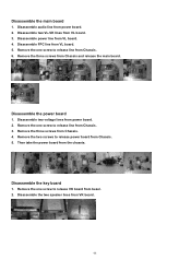
AL1916 Disassembly

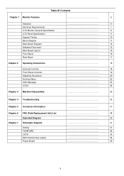
Related Manual Pages


Similar Questions

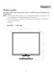
How To Disassemble Acer 1717 Monitor
How to open/disassemble acer monitor Al 1717
How to open/disassemble acer monitor Al 1717
(Posted by csinghsheoran 2 years ago)


Base Disassemble
How do I remove the base so I can get the monitor back into its box for transporting it?
How do I remove the base so I can get the monitor back into its box for transporting it?
(Posted by gwilcock 11 years ago)