
AL1911 Service Guide
Page 1
... Electrical specification ...26 5.2 Pin Assignments...27 6. TROUBLESHOOTING ...30 7.1 Main Procedure...30 8. ELECTRICAL REQUIREMENTS...4 2.1 Standard Test Conditions ...4 2.2 LCD monitor General specification...4 2.3 LCD Panel Specification ...5 2.4 Input Signals ...10 2.5 Controls ...14 2.6 White Color Temperature ...16 2.7 Power Management ...17 2.8......21 3.5 Connector Type...21 3.6 Connector pin assignment ...21 4. AL1911 TFT LCD MONITOR CONTENTS 1. VM-902 AUDIO BOARD...28 6.1 Description...28 6.2 Connector Locations...28 7. INTRODUCTION...3 1.1 Scope ...3 1.2 Description...3 2.
... Electrical specification ...26 5.2 Pin Assignments...27 6. TROUBLESHOOTING ...30 7.1 Main Procedure...30 8. ELECTRICAL REQUIREMENTS...4 2.1 Standard Test Conditions ...4 2.2 LCD monitor General specification...4 2.3 LCD Panel Specification ...5 2.4 Input Signals ...10 2.5 Controls ...14 2.6 White Color Temperature ...16 2.7 Power Management ...17 2.8......21 3.5 Connector Type...21 3.6 Connector pin assignment ...21 4. AL1911 TFT LCD MONITOR CONTENTS 1. VM-902 AUDIO BOARD...28 6.1 Description...28 6.2 Connector Locations...28 7. INTRODUCTION...3 1.1 Scope ...3 1.2 Description...3 2.
AL1911 Service Guide
Page 3
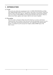
...in addition MTBF target is designed with the latest LCD technology to provide a performance oriented product with volume control to the traditional CRT monitor, it consumes less power and gets less weight in stereo audio amplifier with no radiation. It also supports VESA DPMS power management ... 1.1 Scope This specification defines the requirements for the 19" MICRO-PROCESSOR based Multimode supported high resolution color LCD monitor, This monitor can be directly connected to general 15 pin D-sub VGA connector, eliminates the requirement of speakers. 1.2 Description The LCD...
...in addition MTBF target is designed with the latest LCD technology to provide a performance oriented product with volume control to the traditional CRT monitor, it consumes less power and gets less weight in stereo audio amplifier with no radiation. It also supports VESA DPMS power management ... 1.1 Scope This specification defines the requirements for the 19" MICRO-PROCESSOR based Multimode supported high resolution color LCD monitor, This monitor can be directly connected to general 15 pin D-sub VGA connector, eliminates the requirement of speakers. 1.2 Description The LCD...
AL1911 Service Guide
Page 4
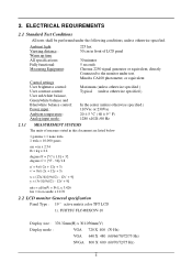
... gauss cm = in front of LCD panel 30 minutes 5 seconds Chroma 2250 signal generator or equivalent, directly Connected to the monitor under the following conditions, unless otherwise specified. FUJITSU FLC48SXC8V-10 Display size : 376.32mm(H) x 301.056mm(V) Display mode :... + 12y + 3) x = (27u'/4)/[(9u'/2) - 12v' + 9] y = (3v')/[(9u'/2) - 12v' + 9] nits = cd/(m2) = Ft-L x 3.426 lux = foot-candle x 10.76 2.2 LCD monitor General specification Panel Type : 19 " active matrix color TFT LCD 1). ELECTRICAL REQUIREMENTS 2.1 Standard Test Conditions All tests shall be performed under test.
... gauss cm = in front of LCD panel 30 minutes 5 seconds Chroma 2250 signal generator or equivalent, directly Connected to the monitor under the following conditions, unless otherwise specified. FUJITSU FLC48SXC8V-10 Display size : 376.32mm(H) x 301.056mm(V) Display mode :... + 12y + 3) x = (27u'/4)/[(9u'/2) - 12v' + 9] y = (3v')/[(9u'/2) - 12v' + 9] nits = cd/(m2) = Ft-L x 3.426 lux = foot-candle x 10.76 2.2 LCD monitor General specification Panel Type : 19 " active matrix color TFT LCD 1). ELECTRICAL REQUIREMENTS 2.1 Standard Test Conditions All tests shall be performed under test.
AL1911 Service Guide
Page 11
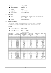
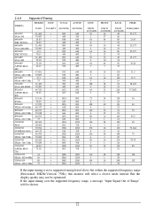
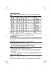
... does not match the supported timing the display optimization will not be assured. • Horizontal Frequency 24KHz --80KHz • Vertical Frequency 56Hz ---------75Hz DISPLAY MODES MONITOR MODE NO. 1 2 3 4 5 6 7 8 9 10 11 12 13 14 15 16 17 18 19 20 21 SCREEN RESOLUTION 640x350 640X400 640X400 640X400 640X480 640X480 640X480 640X480 720X400...
... does not match the supported timing the display optimization will not be assured. • Horizontal Frequency 24KHz --80KHz • Vertical Frequency 56Hz ---------75Hz DISPLAY MODES MONITOR MODE NO. 1 2 3 4 5 6 7 8 9 10 11 12 13 14 15 16 17 18 19 20 21 SCREEN RESOLUTION 640x350 640X400 640X400 640X400 640X480 640X480 640X480 640X480 720X400...
AL1911 Service Guide
Page 12
... 16 248 135 3 1 38 If the input timing is not a supported timing listed above but within the supported frequency range (Horizontal: 80KHz,Vertical: 75Hz), this monitor will be optimized. If the input timing over the supported frequency range, a message "Input Signal Out of Range" will select a closest mode instead. VGA-480...
... 16 248 135 3 1 38 If the input timing is not a supported timing listed above but within the supported frequency range (Horizontal: 80KHz,Vertical: 75Hz), this monitor will be optimized. If the input timing over the supported frequency range, a message "Input Signal Out of Range" will select a closest mode instead. VGA-480...
AL1911 Service Guide
Page 13
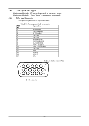
2.4.5 85Hz refresh rate Support Monitor should display "Out of plastic parts: Blue (PC99) 5 1 10 6 15 11 D-sub connector 13 Pin assignment for D-sub connector PIN Separate Sync NO. 1 RED VIDEO 2 ... 13 H.SYNC 14 V.SYNC 15 SCL Color of Range" warning menu at this mode. 2.4.6 Video input Connector Analog Video input Connector: 15pins mini D-Sub Table 2.4.5. Monitor should display 85Hz refresh rate mode as emergency mode.
2.4.5 85Hz refresh rate Support Monitor should display "Out of plastic parts: Blue (PC99) 5 1 10 6 15 11 D-sub connector 13 Pin assignment for D-sub connector PIN Separate Sync NO. 1 RED VIDEO 2 ... 13 H.SYNC 14 V.SYNC 15 SCL Color of Range" warning menu at this mode. 2.4.6 Video input Connector Analog Video input Connector: 15pins mini D-Sub Table 2.4.5. Monitor should display 85Hz refresh rate mode as emergency mode.
AL1911 Service Guide
Page 14
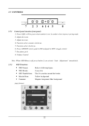
... LED, will be amber when in power saving mode. 2. Adjust decrease. 3. Function select counter-clockwise. 5. Volume Control. Function select clockwise. 6. Adjust increase. 4. be green when monitor is off, press button 2 can activate "Auto Adjustment" immediately. 2.5.2 OSD Functions • OSD Format: Refer to OFF. (toggle switch) 7. 2.5 CONTROLS 2.5.1 Control panel...
... LED, will be amber when in power saving mode. 2. Adjust decrease. 3. Function select counter-clockwise. 5. Volume Control. Function select clockwise. 6. Adjust increase. 4. be green when monitor is off, press button 2 can activate "Auto Adjustment" immediately. 2.5.2 OSD Functions • OSD Format: Refer to OFF. (toggle switch) 7. 2.5 CONTROLS 2.5.1 Control panel...

AL1911 Service Guide
Page 17
2.7 Power Management 2.7.1 Meet VESA DPMS proposal The monitor must appropriately display the DPMS state, For example: DPMS ON : The power LED is Green DPMS OFF : The power LED is 3 seconds maximun. 2.7.3 Power Connector ... off 3 Wmax Dark disconnection 3 Wmax Dark (power off) Amber (power on) AC power off 1 Wmax Dark u Power saving states are measured with a minimum of the monitor must comply with the Microsoft On Now specification, with speakers attached but not worked.
2.7 Power Management 2.7.1 Meet VESA DPMS proposal The monitor must appropriately display the DPMS state, For example: DPMS ON : The power LED is Green DPMS OFF : The power LED is 3 seconds maximun. 2.7.3 Power Connector ... off 3 Wmax Dark disconnection 3 Wmax Dark (power off) Amber (power on) AC power off 1 Wmax Dark u Power saving states are measured with a minimum of the monitor must comply with the Microsoft On Now specification, with speakers attached but not worked.
AL1911 Service Guide
Page 18
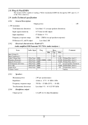
... Item Input Voltage(V) Input Current(m A) Audio Voltage Gain Frequency Response Signal to Noise ratio Total harmonic distortion Cross talk Output Watt. 2.8 Plug & Play(EDID) The monitor will be capable of sending a VESA standardized EDID file through the DDC (pins 12, 15 of the VGA connector). 2.9 Audio Technical specification 2.9.1 General Description: + 1W...
... Item Input Voltage(V) Input Current(m A) Audio Voltage Gain Frequency Response Signal to Noise ratio Total harmonic distortion Cross talk Output Watt. 2.8 Plug & Play(EDID) The monitor will be capable of sending a VESA standardized EDID file through the DDC (pins 12, 15 of the VGA connector). 2.9 Audio Technical specification 2.9.1 General Description: + 1W...
AL1911 Service Guide
Page 19
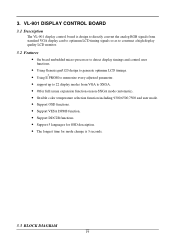
... to directly convert the analog RGB signals from standard VGA display card to optimum LCD timing signals so as to construct a high display quality LCD monitor. 3.2 Features • On board embedded micro-processor to detect display timings and control user functions. • Using Genesis gm5120 design to generate optimum LCD timings...
... to directly convert the analog RGB signals from standard VGA display card to optimum LCD timing signals so as to construct a high display quality LCD monitor. 3.2 Features • On board embedded micro-processor to detect display timings and control user functions. • Using Genesis gm5120 design to generate optimum LCD timings...
AL1911 Service Guide
Page 23
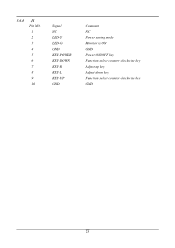
3.6.4 J1 Pin NO. 1 2 3 4 5 6 7 8 9 10 Signal NC LED-Y LED-G GND KEY-POWER KEY-DOWN KEY-R KEY-L KEY-UP GND Comment NC Power saving mode Monitor is ON GND Power ON/OFF key Function select counter-clockwise key Adjust up key Adjust down key Function select counter-clockwise key GND 23
3.6.4 J1 Pin NO. 1 2 3 4 5 6 7 8 9 10 Signal NC LED-Y LED-G GND KEY-POWER KEY-DOWN KEY-R KEY-L KEY-UP GND Comment NC Power saving mode Monitor is ON GND Power ON/OFF key Function select counter-clockwise key Adjust up key Adjust down key Function select counter-clockwise key GND 23
AL1911 Service Guide
Page 24
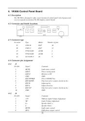
... KEY-POWER KEY-DOWN KEY-R KEY-L KEY-UP GND 4.4.2 J6 Pin NO. 1 2 3 4 5 6 Signal +5V VR L+ LMUTE HP-S Maker E&T E&T ACER ACER SC Number of pins 10 11 2 2 9 Comment Audio mute control Power saving mode Monitor is ON GND Power ON/OFF key Function select counter-clockwise key Adjust up key Adjust down key Function...
... KEY-POWER KEY-DOWN KEY-R KEY-L KEY-UP GND 4.4.2 J6 Pin NO. 1 2 3 4 5 6 Signal +5V VR L+ LMUTE HP-S Maker E&T E&T ACER ACER SC Number of pins 10 11 2 2 9 Comment Audio mute control Power saving mode Monitor is ON GND Power ON/OFF key Function select counter-clockwise key Adjust up key Adjust down key Function...
AL1911 Service Guide
Page 36
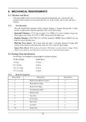
... shock in each direction in each of three mutually perpendicular axes, referenced to the position of the system as it is in each axis, for monitor product Product Weight height Specs Half Sine Wave Shock: 120 G peak, half sine pulse, 2 ms pulse duration.
... shock in each direction in each of three mutually perpendicular axes, referenced to the position of the system as it is in each axis, for monitor product Product Weight height Specs Half Sine Wave Shock: 120 G peak, half sine pulse, 2 ms pulse duration.
AL1911 Service Guide
Page 41
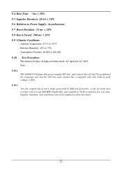
..., so the test must uses a scope with at least 400 MHz bandwidth, and coupled to 50 Ω to 35°C - Ambient Temperature: 15°C to monitor the rise-time, impulse, duration, and repetition rate of the impulses within one burst. 41 Atmospheric Pressure: 86 kPa to 106 kPa 9.10 Test Procedure...
..., so the test must uses a scope with at least 400 MHz bandwidth, and coupled to 50 Ω to 35°C - Ambient Temperature: 15°C to monitor the rise-time, impulse, duration, and repetition rate of the impulses within one burst. 41 Atmospheric Pressure: 86 kPa to 106 kPa 9.10 Test Procedure...
AL1911 User Guide
Page 1
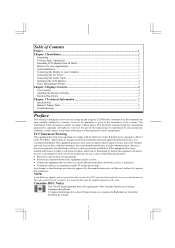
...without prior written permission of the manufacturer. Table of Contents Preface ...1 Chapter 1 Installation...2 Unpacking ...2 Viewing Angle Adjustment...2 Detaching LCD Monitor from that to which can radiate radio frequency energy, and if not installed and used . All rights are designed to provide ...cord is required in this equipment. however, no guarantee that interference will not occur in setting up and using the LCD Monitor. The information in order to meet the FCC emission limits and also to prevent interference to the correctness of the Canadian Interference...
...without prior written permission of the manufacturer. Table of Contents Preface ...1 Chapter 1 Installation...2 Unpacking ...2 Viewing Angle Adjustment...2 Detaching LCD Monitor from that to which can radiate radio frequency energy, and if not installed and used . All rights are designed to provide ...cord is required in this equipment. however, no guarantee that interference will not occur in setting up and using the LCD Monitor. The information in order to meet the FCC emission limits and also to prevent interference to the correctness of the Canadian Interference...
AL1911 User Guide
Page 2
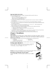
... this unit by an authorized technician. 5. Excess pressure may cause permanent damage to the LCD screen. Store LCD Monitor in damaging the Monitor and Monitor stand. Detaching LCD Monitor from -5°to +25°.(See fig. 1-1)& Left / Right -45° to +45° Figure...this device to a power outlet. Chapter 1 Installation Unpacking Before unpacking the LCD Monitor, prepare a suitable workspace for sufficient airflow. After you unpack the LCD Monitor, make sure that LCD Monitor has enough space around it . 3. Important Safety Instructions Please read the following ...
... this unit by an authorized technician. 5. Excess pressure may cause permanent damage to the LCD screen. Store LCD Monitor in damaging the Monitor and Monitor stand. Detaching LCD Monitor from -5°to +25°.(See fig. 1-1)& Left / Right -45° to +45° Figure...this device to a power outlet. Chapter 1 Installation Unpacking Before unpacking the LCD Monitor, prepare a suitable workspace for sufficient airflow. After you unpack the LCD Monitor, make sure that LCD Monitor has enough space around it . 3. Important Safety Instructions Please read the following ...
AL1911 User Guide
Page 3
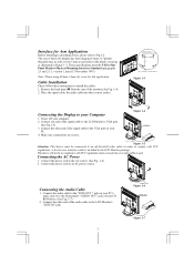
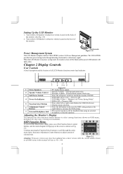
... cable to the VGA port on your PC's audio card or to the front panel's "AUDIO OUT" jack of the signal cable to the LCD Monitor's VGA port. (See Fig 1-5) 3. Cable Installation Please follow these instructions to the AC socket. (See Fig. 1-6) 2. Figure 1-3 Connecting the Display to your PC....This device will not be connected to an off your CD ROM drive. (See Fig. 1-7) 2. Power off -the-shelf video cable in the LCD Monitor package. Make sure connections are secure. A ferrite-core interface cable is used. Connect the other end of this application. Place the signal cable, the ...
... cable to the VGA port on your PC's audio card or to the front panel's "AUDIO OUT" jack of the signal cable to the LCD Monitor's VGA port. (See Fig 1-5) 3. Cable Installation Please follow these instructions to the AC socket. (See Fig. 1-6) 2. Figure 1-3 Connecting the Display to your PC....This device will not be connected to an off your CD ROM drive. (See Fig. 1-7) 2. Power off -the-shelf video cable in the LCD Monitor package. Make sure connections are secure. A ferrite-core interface cable is used. Connect the other end of this application. Place the signal cable, the ...
AL1911 User Guide
Page 4
...Figure 2-1 PC Audio Stereo output. 2 Speaker Volume Control 3 Soft Power Switch Increase Volume - Power is in "Power Saving Mode". When the LCD Monitor is OFF. 5 Function Select Buttons Press either left button to decrease the OSD setting and press the right button to increase the OSD setting. 7 ...External Headphone Jack The monitor speakers will stay as shown on the screen as Ver. 1.00. 4 LED is ON. Figure 2-2 Attention: Firmware revision may have been ...
...Figure 2-1 PC Audio Stereo output. 2 Speaker Volume Control 3 Soft Power Switch Increase Volume - Power is in "Power Saving Mode". When the LCD Monitor is OFF. 5 Function Select Buttons Press either left button to decrease the OSD setting and press the right button to increase the OSD setting. 7 ...External Headphone Jack The monitor speakers will stay as shown on the screen as Ver. 1.00. 4 LED is ON. Figure 2-2 Attention: Firmware revision may have been ...
AL1911 User Guide
Page 9
...display mode or new VGA card is selected. If there are secured, and the system is NOT included in OSD menu again and adjust the monitor screen to the normal PC operating environment. Click "No" on "Shut Down Windows" and back to its most suitable available timing. APPLE ...MAC-480 -/- VESA-768-70 Hz +/+ VESA-768-75 Hz -/- Move to "Phase" function in table below, this LCD Monitor. If step 2 doesn't work, connect your PC system to "Shut Down Windows" status while you have chosen an output timing that is still no...
...display mode or new VGA card is selected. If there are secured, and the system is NOT included in OSD menu again and adjust the monitor screen to the normal PC operating environment. Click "No" on "Shut Down Windows" and back to its most suitable available timing. APPLE ...MAC-480 -/- VESA-768-70 Hz +/+ VESA-768-75 Hz -/- Move to "Phase" function in table below, this LCD Monitor. If step 2 doesn't work, connect your PC system to "Shut Down Windows" status while you have chosen an output timing that is still no...


