
AL1515 User's Guide
Page 1
... Safety Instructions ...3 Chapter 1 Installation ...4 Unpacking...4 Connecting the LCD Monitor and Base 4 Viewing Angle Adjustment...4 Detaching LCD Monitor from Its Stand 5 Interface for Arm Applications ...5 Connecting the Display ...5 Connecting the AC Power...5 Connecting the Audio Cable (For AL1515 m and AL1515 bm 6 Power Management System ...6 Chapter 2 Display Controls 7 General Instructions ...7 Front Panel Control...8 How To Adjust A Setting...9 Adjusting The Picture ...9 Chapter 3 Technical Information 11 Specifications...11 Standard Timing Table...13 Troubleshooting ...15...
... Safety Instructions ...3 Chapter 1 Installation ...4 Unpacking...4 Connecting the LCD Monitor and Base 4 Viewing Angle Adjustment...4 Detaching LCD Monitor from Its Stand 5 Interface for Arm Applications ...5 Connecting the Display ...5 Connecting the AC Power...5 Connecting the Audio Cable (For AL1515 m and AL1515 bm 6 Power Management System ...6 Chapter 2 Display Controls 7 General Instructions ...7 Front Panel Control...8 How To Adjust A Setting...9 Adjusting The Picture ...9 Chapter 3 Technical Information 11 Specifications...11 Standard Timing Table...13 Troubleshooting ...15...
AL1515 User's Guide
Page 2
... not occur in setting up and using the LCD Monitor. Preface This manual is designed to assist users in a particular installation. These limits are reserved. If this equipment. Warning Use only shielded signal cables to connect I/O devices to this equipment does cause harmful interference to radio or television reception, which can radiate radio frequency energy, and if not installed and used in accordance with...
... not occur in setting up and using the LCD Monitor. Preface This manual is designed to assist users in a particular installation. These limits are reserved. If this equipment. Warning Use only shielded signal cables to connect I/O devices to this equipment does cause harmful interference to radio or television reception, which can radiate radio frequency energy, and if not installed and used in accordance with...
AL1515 User's Guide
Page 3
... place the LCD Monitor near a window. Exposing the monitor to the display. 4. Storing the LCD Monitor outside this unit by an authorized technician. 5. Power off LCD Monitor and unplug the AC Cord. -- Store LCD Monitor in permanent damage. 6. Servicing of any of -20° ~ 60°C (or -4° ~ 140°F). If any nature should be retained for future use the supplied main lead to connect the monitor. Excess...
... place the LCD Monitor near a window. Exposing the monitor to the display. 4. Storing the LCD Monitor outside this unit by an authorized technician. 5. Power off LCD Monitor and unplug the AC Cord. -- Store LCD Monitor in permanent damage. 6. Servicing of any of -20° ~ 60°C (or -4° ~ 140°F). If any nature should be retained for future use the supplied main lead to connect the monitor. Excess...
AL1515 User's Guide
Page 4
... box: * LCD Monitor * User's Manual * Quick Guide * 1.8M Monitor-to-PC VGA Cable * 1.8M Stereo Jack Audio Cable (for AL1515 m and AL1515 bm) * 1.8M Power Cord * Base If you find that the Monitor does not become too hot. Ensure that LCD Monitor has enough space around it on the base faces forward. 3. Place the LCD securely on the base as stated above. Though the LCD Monitor uses very little power, some ventilation is needed to...
... box: * LCD Monitor * User's Manual * Quick Guide * 1.8M Monitor-to-PC VGA Cable * 1.8M Stereo Jack Audio Cable (for AL1515 m and AL1515 bm) * 1.8M Power Cord * Base If you find that the Monitor does not become too hot. Ensure that LCD Monitor has enough space around it on the base faces forward. 3. Place the LCD securely on the base as stated above. Though the LCD Monitor uses very little power, some ventilation is needed to...
AL1515 User's Guide
Page 5
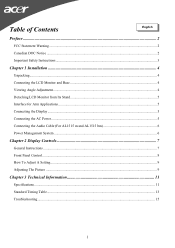
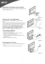
Power off your PC. 4. Connecting the AC Power 1. Connect the power cord to an AC power source. 5 Figure 1-3 Figure 1-4 Figure 1-5 Figure 1-6 These specifications meet the VESA Flat Panel Monitor Physical Mounting Interface Standard (paragraphs 2.1 and 2.1.3, version 1, dated 13 November 1997). Connecting the Display 1. Connect the other end of the signal cable to release. Connect the power cord to the LCD Monitor.(See Fig. 1-6) 2. Interface for Arm Applications Before installing to mounting device, please refer to the LCD Monitor's VGA port.(See...
Power off your PC. 4. Connecting the AC Power 1. Connect the power cord to an AC power source. 5 Figure 1-3 Figure 1-4 Figure 1-5 Figure 1-6 These specifications meet the VESA Flat Panel Monitor Physical Mounting Interface Standard (paragraphs 2.1 and 2.1.3, version 1, dated 13 November 1997). Connecting the Display 1. Connect the other end of the signal cable to release. Connect the power cord to the LCD Monitor.(See Fig. 1-6) 2. Interface for Arm Applications Before installing to mounting device, please refer to the LCD Monitor's VGA port.(See...
AL1515 User's Guide
Page 6
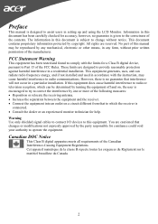
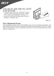
... four power saving modes through detecting a horizontal or vertical sync. Figure 1-7 Power Management System This LCD Monitor complies with the VESA DPMS (version 1.0) Power Management guidelines. When the LCD Monitor is in power saving mode, the monitor screen will be blank and the power LED indicator will light yellow. 6 signal. Connect the audio cable to the " LINE OUT " jack on your CD ROM drive. (See Fig. 1-7) 2. Connect the other end of the audio cable to the front panel's "AUDIO OUT...
... four power saving modes through detecting a horizontal or vertical sync. Figure 1-7 Power Management System This LCD Monitor complies with the VESA DPMS (version 1.0) Power Management guidelines. When the LCD Monitor is in power saving mode, the monitor screen will be blank and the power LED indicator will light yellow. 6 signal. Connect the audio cable to the " LINE OUT " jack on your CD ROM drive. (See Fig. 1-7) 2. Connect the other end of the audio cable to the front panel's "AUDIO OUT...
AL1515 User's Guide
Page 7
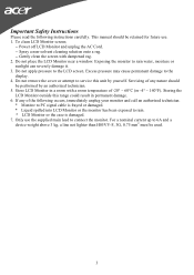
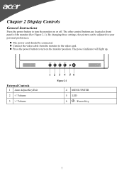
By changing these settings, the picture can be connected. Connect the video cable from the monitor to your personal preferences. Press the power button to turn the monitor on the monitor position. External Controls 1 Auto Adjust Key/Exit 2 / Volume Figure 2-1 4 MENU/ENTER 5 LED 6 / Power Key 7 The other control buttons are located at front panel of the monitor (See Figure 2-1). The power indicator will light up. Chapter 2 Display Controls General Instructions Press the power button to turn on or off. The power cord should be adjusted to the video card.
By changing these settings, the picture can be connected. Connect the video cable from the monitor to your personal preferences. Press the power button to turn the monitor on the monitor position. External Controls 1 Auto Adjust Key/Exit 2 / Volume Figure 2-1 4 MENU/ENTER 5 LED 6 / Power Key 7 The other control buttons are located at front panel of the monitor (See Figure 2-1). The power indicator will light up. Chapter 2 Display Controls General Instructions Press the power button to turn on or off. The power cord should be adjusted to the video card.

AL1515 User's Guide
Page 8
Power On mode. Front Panel Control /Power Button: Press this button to set the HPos, VPos, Clock and Focus. Auto Adjust button / Exit: 1. The Auto Adjustment function is used to turn the monitor ON or OFF, And display the monitor's state. NOTES ‧ Do not install the monitor in a location near heat sources such as radiators or air ducts, or in a place subject to direct sunlight, or excessive dust or mechanical vibration...
Power On mode. Front Panel Control /Power Button: Press this button to set the HPos, VPos, Clock and Focus. Auto Adjust button / Exit: 1. The Auto Adjustment function is used to turn the monitor ON or OFF, And display the monitor's state. NOTES ‧ Do not install the monitor in a location near heat sources such as radiators or air ducts, or in a place subject to direct sunlight, or excessive dust or mechanical vibration...
AL1515 User's Guide
Page 9
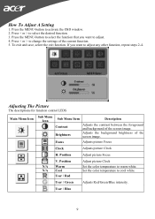
... Contrast Brightness Description Adjusts the contrast between the foreground and background of the screen image. Press the MENU-button to change the settings of the current function. 5. If you want to select the desired function. 3. Adjusts the background brightness of the screen image. To exit and save, select the exit function. Focus Adjusts picture Focus Clock Adjusts picture Clock H. Press < or > to activate the OSD window. 2. User / Green Adjusts Red/Green/Blue intensity. Set the color temperature to warm white. User / Blue 9 Position Adjust picture...
... Contrast Brightness Description Adjusts the contrast between the foreground and background of the screen image. Press the MENU-button to change the settings of the current function. 5. If you want to select the desired function. 3. Adjusts the background brightness of the screen image. To exit and save, select the exit function. Focus Adjusts picture Focus Clock Adjusts picture Clock H. Press < or > to activate the OSD window. 2. User / Green Adjusts Red/Green/Blue intensity. Set the color temperature to warm white. User / Blue 9 Position Adjust picture...
AL1515 User's Guide
Page 10
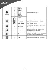
...Adjust the vertical position of the OSD. Adjust the horizontal position of the OSD. N/A Exit Save user adjustment and OSD disappear. 10 N/A Auto Config Auto Adjust the H/V Position, Focus and Clock of Auto-configuration and set the color temperature to Cool. N/A Reset Clear each old status of picture. V. N/A Information Show the resolution, H/V frequency and input port of current iput timing. Position Multi-language selection. N/A English N/A N/A Deutsch N/A Français N/A Español N/A Italiano N/A N/A 日本語 H. OSD Timeout Adjust the OSD...
...Adjust the vertical position of the OSD. Adjust the horizontal position of the OSD. N/A Exit Save user adjustment and OSD disappear. 10 N/A Auto Config Auto Adjust the H/V Position, Focus and Clock of Auto-configuration and set the color temperature to Cool. N/A Reset Clear each old status of picture. V. N/A Information Show the resolution, H/V frequency and input port of current iput timing. Position Multi-language selection. N/A English N/A N/A Deutsch N/A Français N/A Español N/A Italiano N/A N/A 日本語 H. OSD Timeout Adjust the OSD...
AL1515 User's Guide
Page 11
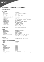
...+45° Horizontal: -65° ~ +65° Display Colors 16.7M with FRC or Dithering Video Input Signal Input Impedance Polarity Amplitude Multi-mode Supported Analogue RGB 0.7Vp-p 75 Ohm ± 2% Positive, Negative 0 - 0.7 ± 0.05 Vp Horizontal Frequency: 24 ~ 60 KHz Vertical Frequency: 49 ~ 75 Hz Control Power switch On/Off switch with LED indicator Audio (AL1515 m/AL1515 bm) Input 500mVrms Output 1W+1W OSD Brightness Contrast Horizontal Position Vertical Position Phase Clock Display Mode Setup Digital Digital Digital Digital Digital Digital Use EEPROM to save settings in...
...+45° Horizontal: -65° ~ +65° Display Colors 16.7M with FRC or Dithering Video Input Signal Input Impedance Polarity Amplitude Multi-mode Supported Analogue RGB 0.7Vp-p 75 Ohm ± 2% Positive, Negative 0 - 0.7 ± 0.05 Vp Horizontal Frequency: 24 ~ 60 KHz Vertical Frequency: 49 ~ 75 Hz Control Power switch On/Off switch with LED indicator Audio (AL1515 m/AL1515 bm) Input 500mVrms Output 1W+1W OSD Brightness Contrast Horizontal Position Vertical Position Phase Clock Display Mode Setup Digital Digital Digital Digital Digital Digital Use EEPROM to save settings in...
AL1515 User's Guide
Page 12
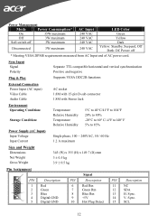
... 240 VAC 240 VAC 240 VAC LED Color Green Yellow Dark Yellow: Standby, Suspend, Off Dark: DC Power off * Meeting VESA DPMS requirements measured from AC Input end of AC power cord. Sync. 14 V. Sync Input Signal Polarity Plug & Play Separate TTL compatible horizontal and vertical synchronization Positive and negative Supports VESA DDC2B functions External Connection Power Input (AC input) Video Cable Audio Cable AC socket 1.8M with 15-pin D-sub connector 1.8M with Stereo Jack Environment Operating...
... 240 VAC 240 VAC 240 VAC LED Color Green Yellow Dark Yellow: Standby, Suspend, Off Dark: DC Power off * Meeting VESA DPMS requirements measured from AC Input end of AC power cord. Sync. 14 V. Sync Input Signal Polarity Plug & Play Separate TTL compatible horizontal and vertical synchronization Positive and negative Supports VESA DDC2B functions External Connection Power Input (AC input) Video Cable Audio Cable AC socket 1.8M with 15-pin D-sub connector 1.8M with Stereo Jack Environment Operating...
AL1515 User's Guide
Page 13
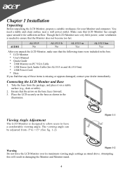
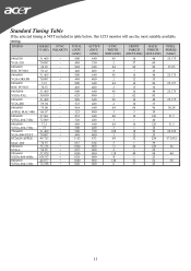
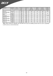
... (DOT/ LINE) ACTIVE (DOT/ LINE) SYNC WIDTH (DOT/LINE) FRONT BACK PORCH PORCH (DOT/LINE) (DOT/LINE) PIXEL FOREQ (MHZ) 640x350 31.469 + 800 640 96 VGA-350 70.087 - 449 350 2 16 ... 96 16 48 25.175 VGA-480 59.94 - 525 480 2 10 33 640x480 35.00 - 864 640 64 APPLE MAC-480 66.67 - 525 480 3 640x480 37.861 - 832 640 40 VESA-480-72Hz 72.809 - ...VESA-600-72Hz 72.188 + 666 600 6 1 39 24 128 36 1 22 40 88 40 1 23 56 64 50 37 23 13 Standard Timing Table If the selected timing is NOT included in table below, this LCD monitor will use...
... (DOT/ LINE) ACTIVE (DOT/ LINE) SYNC WIDTH (DOT/LINE) FRONT BACK PORCH PORCH (DOT/LINE) (DOT/LINE) PIXEL FOREQ (MHZ) 640x350 31.469 + 800 640 96 VGA-350 70.087 - 449 350 2 16 ... 96 16 48 25.175 VGA-480 59.94 - 525 480 2 10 33 640x480 35.00 - 864 640 64 APPLE MAC-480 66.67 - 525 480 3 640x480 37.861 - 832 640 40 VESA-480-72Hz 72.809 - ...VESA-600-72Hz 72.188 + 666 600 6 1 39 24 128 36 1 22 40 88 40 1 23 56 64 50 37 23 13 Standard Timing Table If the selected timing is NOT included in table below, this LCD monitor will use...
AL1515 User's Guide
Page 14
TIMING FH(KHZ) SYNC TOTAL ACTIVE SYNC FRONT BACK PIXEL FV(HZ) POLARITY (DOT/ (DOT/ WIDTH PORCH PORCH FOREQ LINE) LINE) (DOT/LINE) (DOT/LINE) (DOT/LINE) (MHZ) 800x600 46.875 + 1056 800 80 VESA-600-75Hz 75 + 625 600 3 1024x768 48.363 - 1344 1024 136 XGA 60.004 - 806 768 6 1024x768...MAC-768 75.02 - 803 768 3 16 160 49.5 1 21 24 160 65 3 29 16 112 71.664 8 36 24 144 75 3 29 16 176 78.75 1 28 32 176 80 3 29 Note: Mode 640x350, 640x400 and 720x400 will locate on middle position but not sure be expanded to full screen on vertical...
TIMING FH(KHZ) SYNC TOTAL ACTIVE SYNC FRONT BACK PIXEL FV(HZ) POLARITY (DOT/ (DOT/ WIDTH PORCH PORCH FOREQ LINE) LINE) (DOT/LINE) (DOT/LINE) (DOT/LINE) (MHZ) 800x600 46.875 + 1056 800 80 VESA-600-75Hz 75 + 625 600 3 1024x768 48.363 - 1344 1024 136 XGA 60.004 - 806 768 6 1024x768...MAC-768 75.02 - 803 768 3 16 160 49.5 1 21 24 160 65 3 29 16 112 71.664 8 36 24 144 75 3 29 16 176 78.75 1 28 32 176 80 3 29 Note: Mode 640x350, 640x400 and 720x400 will locate on middle position but not sure be expanded to full screen on vertical...
AL1515 User's Guide
Page 15
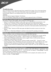
... This LCD Monitor Supports Multiple VGA Modes. In Windows XP open the specific application where the problems appear. 2. Move to Chapter 3 for a listing of Range" message. If your PC system Functions properly with a CRT Monitor but it back on LCD Monitor If you 're in OSD menu again and adjust the monitor screen to LCD monitor at all connections are , take advantage of the "Clock" function in OSD menu and adjust (by this LCD Monitor. Refer to...
... This LCD Monitor Supports Multiple VGA Modes. In Windows XP open the specific application where the problems appear. 2. Move to Chapter 3 for a listing of Range" message. If your PC system Functions properly with a CRT Monitor but it back on LCD Monitor If you 're in OSD menu again and adjust the monitor screen to LCD monitor at all connections are , take advantage of the "Clock" function in OSD menu and adjust (by this LCD Monitor. Refer to...

