
AL1515 LCD Monitor Service Guide
Page 4
... to radio communications. Reorient or relocate the receiving antenna. 2. Consult the dealer or an experienced radio/TV technician for a Class B digital device, pursuant to Part 15 of the following measures: 1.
... to radio communications. Reorient or relocate the receiving antenna. 2. Consult the dealer or an experienced radio/TV technician for a Class B digital device, pursuant to Part 15 of the following measures: 1.
AL1515 LCD Monitor Service Guide
Page 7
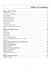
Table of contents Chapter 1 Monitor Feature 8 INTRODUCTION...8 ELECTRICAL REQUIREMEENTS...9 BLOCK DIAGRAM ...15 MONITOR BOARD LAYOUT ...16 SOFTWARE FLOW CHART ...17 GENERAL INSTRUCTIONS ...18 SYSTEM INSTALLATION ...19 POWER BOARD...24 ELECTRICAL ...Operating Instruction 30 CONTROLS ...30 MAIN OSD MENU...31 OSD MESSAGE...33 PLUG AND PLAY ...35 WHITE COLOR TEMPERATURE...36 AUDIO TECHNICAL SPECIFICATION (FOR AL1515 m ONLY 36 SPEAKERS ...37 Chapter 3 Machine Disassembly and Replacement 38 DISASSEMBLY PROCEDURE ...38 Chapter 4 Troubleshooting 41 TROUBLESHOOTING ...41 Chapter 5 Connector ...
Table of contents Chapter 1 Monitor Feature 8 INTRODUCTION...8 ELECTRICAL REQUIREMEENTS...9 BLOCK DIAGRAM ...15 MONITOR BOARD LAYOUT ...16 SOFTWARE FLOW CHART ...17 GENERAL INSTRUCTIONS ...18 SYSTEM INSTALLATION ...19 POWER BOARD...24 ELECTRICAL ...Operating Instruction 30 CONTROLS ...30 MAIN OSD MENU...31 OSD MESSAGE...33 PLUG AND PLAY ...35 WHITE COLOR TEMPERATURE...36 AUDIO TECHNICAL SPECIFICATION (FOR AL1515 m ONLY 36 SPEAKERS ...37 Chapter 3 Machine Disassembly and Replacement 38 DISASSEMBLY PROCEDURE ...38 Chapter 4 Troubleshooting 41 TROUBLESHOOTING ...41 Chapter 5 Connector ...
AL1515 LCD Monitor Service Guide
Page 8
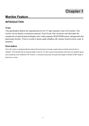
... MTBF target is a build-in stereo audio amplifier with no radiation. Monitor Feature INTRODUCTION Chapter 1 Scope This specification defines the requirements for the 15" high resolution color LCD monitor. It is also a space saving design, allowing more . - 8 - This monitor can be directly connected ...Description The LCD monitor is designed with the latest LCD technology to provide a performance oriented product with volume control to general 15 pin D-sub VGA connector and eliminates the requirement of speakers. This will alleviate the growing health concerns. It also supports VESA...
... MTBF target is a build-in stereo audio amplifier with no radiation. Monitor Feature INTRODUCTION Chapter 1 Scope This specification defines the requirements for the 15" high resolution color LCD monitor. It is also a space saving design, allowing more . - 8 - This monitor can be directly connected ...Description The LCD monitor is designed with the latest LCD technology to provide a performance oriented product with volume control to general 15 pin D-sub VGA connector and eliminates the requirement of speakers. This will alleviate the growing health concerns. It also supports VESA...

AL1515 LCD Monitor Service Guide
Page 10
... Type Resolution Display Dot Display color Brightness Contrast Ratio Response Time Lamp Voltage Lamp Current Viewing Angle Hannstar HSD150SX84 HSD150SX87 15.0" (38cm) 15.0" (38cm) Active matrix color TFT LCD Active matrix color TFT LCD 1024x768 1024x768 1024x(RGB)X768 1024x(RGB)X768... 0.7V peak to peak Sync: TTL positive or negative Signal connector: 15 pin Mini D type, (standard VGA video) 3.5 mm stereo audio jack (Audio) (For AL1515 m only) Audio power: 0.5Wrms + 0.5Wrms (300Hz - 10kHz (S.P.L. - 10 dB))(AL1515 m only) Front control: power on/off with LED select adjustment ...
... Type Resolution Display Dot Display color Brightness Contrast Ratio Response Time Lamp Voltage Lamp Current Viewing Angle Hannstar HSD150SX84 HSD150SX87 15.0" (38cm) 15.0" (38cm) Active matrix color TFT LCD Active matrix color TFT LCD 1024x768 1024x768 1024x(RGB)X768 1024x(RGB)X768... 0.7V peak to peak Sync: TTL positive or negative Signal connector: 15 pin Mini D type, (standard VGA video) 3.5 mm stereo audio jack (Audio) (For AL1515 m only) Audio power: 0.5Wrms + 0.5Wrms (300Hz - 10kHz (S.P.L. - 10 dB))(AL1515 m only) Front control: power on/off with LED select adjustment ...

AL1515 LCD Monitor Service Guide
Page 12
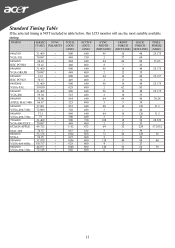
... FH(KHZ) SYNC TOTAL ACTIVE SYNC FRONT BACK PIXEL FV(HZ) 31.469 70.087 24.83 56.42 31.469 70.087 31.5 70.15 31.469 59.94 37.861 72.809 37.5 75 31.469 70.087 49.725 74.55 35.156 56.25 37.879 60...
... FH(KHZ) SYNC TOTAL ACTIVE SYNC FRONT BACK PIXEL FV(HZ) 31.469 70.087 24.83 56.42 31.469 70.087 31.5 70.15 31.469 59.94 37.861 72.809 37.5 75 31.469 70.087 49.725 74.55 35.156 56.25 37.879 60...

AL1515 LCD Monitor Service Guide
Page 13
Video input Connector Analog Video input Connector: 15pins mini D-Sub Table 2.4.5. Support Modes There will be 28 total support modes to accommodate the above mode and other video modes within the frequency range of plastic parts: Blue (PC99) 5 1 10 6 15 11 D-sub connector - 13 - Separate Sync 1 RED VIDEO 2 GREEN VIDEO 3 BLUE VIDEO 4 GROUND 5 GROUND 6 RED GROUND 7 GREEN GROUND 8 BLUE GROUND 9 PC5V (+5V DDC) 10 CABLE DETECTION 11 GROUND 12 SDA 13 H.SYNC 14 V.SYNC 15 SCL Color of the monitor. Pin assignment for D-sub connector PIN NO.
Video input Connector Analog Video input Connector: 15pins mini D-Sub Table 2.4.5. Support Modes There will be 28 total support modes to accommodate the above mode and other video modes within the frequency range of plastic parts: Blue (PC99) 5 1 10 6 15 11 D-sub connector - 13 - Separate Sync 1 RED VIDEO 2 GREEN VIDEO 3 BLUE VIDEO 4 GROUND 5 GROUND 6 RED GROUND 7 GREEN GROUND 8 BLUE GROUND 9 PC5V (+5V DDC) 10 CABLE DETECTION 11 GROUND 12 SDA 13 H.SYNC 14 V.SYNC 15 SCL Color of the monitor. Pin assignment for D-sub connector PIN NO.
AL1515 LCD Monitor Service Guide
Page 23
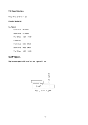
Tilt Base Rotation Tilt up 15 ± 2°/ down 5 ±2° Plastic Material For TCO99 Front Bezel PC+ABS Back Cover PC+ABS The Others ABS 94HB For MPRII Front Bezel ABS 94V-0 Back Cover ABS 94V-0 The Others ABS 94HB GAP Spec. Gap between panel with bezel is 0 mm < gap < 1.2 mm - 23 -
Tilt Base Rotation Tilt up 15 ± 2°/ down 5 ±2° Plastic Material For TCO99 Front Bezel PC+ABS Back Cover PC+ABS The Others ABS 94HB For MPRII Front Bezel ABS 94V-0 Back Cover ABS 94V-0 The Others ABS 94HB GAP Spec. Gap between panel with bezel is 0 mm < gap < 1.2 mm - 23 -
AL1515 LCD Monitor Service Guide
Page 29
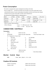
...state to avoid unintentionally entering of a power saving stage during display resolution and timing mode changes. Analog RGB : Monitor rear side / Data Cable : 15-pin D-sub female / male Pin - F < 10Hz duty cycle > 25% CONNECTORS / CONTROLS Connectors - The recovery from Off-state requires no ...Serial Data for ISP 4 Serial Clock for ISP 12 Serial Data for DDC 5 Ground 13 H-Sync. 6 Red Ground 14 V-Sync. 7 Green Ground 15 Serial Clock for PC : 3.5mm Stereo female Monitor Control Keys KEY : Power , Menu , Adjust +/- , Vol +/-, Auto Position Of Controls Position ...
...state to avoid unintentionally entering of a power saving stage during display resolution and timing mode changes. Analog RGB : Monitor rear side / Data Cable : 15-pin D-sub female / male Pin - F < 10Hz duty cycle > 25% CONNECTORS / CONTROLS Connectors - The recovery from Off-state requires no ...Serial Data for ISP 4 Serial Clock for ISP 12 Serial Data for DDC 5 Ground 13 H-Sync. 6 Red Ground 14 V-Sync. 7 Green Ground 15 Serial Clock for PC : 3.5mm Stereo female Monitor Control Keys KEY : Power , Menu , Adjust +/- , Vol +/-, Auto Position Of Controls Position ...
AL1515 LCD Monitor Service Guide
Page 35
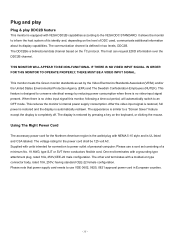
... use a cord set by pressing a key on the level of a minimum No. 18 AWG, type SJT or SVT three conductors flexible cord. Supplied with NEMA 5-15 style and is automatically redrawn. The other end terminates with a grounding type attachment plug, rated 10A, 250V,CEE-22 male configuration. The communication channel is...
... use a cord set by pressing a key on the level of a minimum No. 18 AWG, type SJT or SVT three conductors flexible cord. Supplied with NEMA 5-15 style and is automatically redrawn. The other end terminates with a grounding type attachment plug, rated 10A, 250V,CEE-22 male configuration. The communication channel is...
AL1515 LCD Monitor Service Guide
Page 37
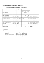
... Watt. Comment Min. Volume Control Audio Input Freq. Spec. Typ. Analog Speakers Maximum power Impedance Frequency response range Total harmonic distortion : 2 W per speaker(max) : 4 ohm +/- 15 % @ 1kHz 1.0Hz : 300 Hz - 20 kHz (S.P.L. - 10 dB) : Less than 5 % @ 0.125 W 1kHz - 37 - Max. - 0.5Vm -
... Watt. Comment Min. Volume Control Audio Input Freq. Spec. Typ. Analog Speakers Maximum power Impedance Frequency response range Total harmonic distortion : 2 W per speaker(max) : 4 ohm +/- 15 % @ 1kHz 1.0Hz : 300 Hz - 20 kHz (S.P.L. - 10 dB) : Less than 5 % @ 0.125 W 1kHz - 37 - Max. - 0.5Vm -

AL1515 LCD Monitor Service Guide
Page 45
Left PIN3. right PIN2. Pin assignment for D-sub connector Chapter 5 Separate Sync 5 10 15 PIN NO. 1 1 RED VIDEO 2 GREEN VIDEO 6 3 BLUE VIDEO 11 4 GROUND 5 GROUND 6 RED GROUND 7 GREEN GROUND 8 BLUE GROUND 9 PC5V (+5V DDC) 10 CABLE DETECTION 11 GROUND 12 SDA 13 H.SYNC 14 V.SYNC 15 SCL 45 Gnd : CEE22 typed connector : Line-in receptacle J1 1 2 3 PHONEJACK STEREO Video input Connector Analog Video input Connector: 15pins mini D-Sub Table 2.4.5. Connector Information Phonejack stereo PIN1.
Left PIN3. right PIN2. Pin assignment for D-sub connector Chapter 5 Separate Sync 5 10 15 PIN NO. 1 1 RED VIDEO 2 GREEN VIDEO 6 3 BLUE VIDEO 11 4 GROUND 5 GROUND 6 RED GROUND 7 GREEN GROUND 8 BLUE GROUND 9 PC5V (+5V DDC) 10 CABLE DETECTION 11 GROUND 12 SDA 13 H.SYNC 14 V.SYNC 15 SCL 45 Gnd : CEE22 typed connector : Line-in receptacle J1 1 2 3 PHONEJACK STEREO Video input Connector Analog Video input Connector: 15pins mini D-Sub Table 2.4.5. Connector Information Phonejack stereo PIN1.
AL1515 User's Guide
Page 1
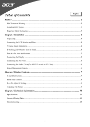
... 4 Viewing Angle Adjustment...4 Detaching LCD Monitor from Its Stand 5 Interface for Arm Applications ...5 Connecting the Display ...5 Connecting the AC Power...5 Connecting the Audio Cable (For AL1515 m and AL1515 bm 6 Power Management System ...6 Chapter 2 Display Controls 7 General Instructions ...7 Front Panel Control...8 How To Adjust A Setting...9 Adjusting The Picture ...9 Chapter 3 Technical Information 11 Specifications...
... 4 Viewing Angle Adjustment...4 Detaching LCD Monitor from Its Stand 5 Interface for Arm Applications ...5 Connecting the Display ...5 Connecting the AC Power...5 Connecting the Audio Cable (For AL1515 m and AL1515 bm 6 Power Management System ...6 Chapter 2 Display Controls 7 General Instructions ...7 Front Panel Control...8 How To Adjust A Setting...9 Adjusting The Picture ...9 Chapter 3 Technical Information 11 Specifications...
AL1515 User's Guide
Page 2
... any mechanical, electronic or other means, in any form, without notice. You are reserved. Warning Use only shielded signal cables to connect I/O devices to Part 15 of the Canadian Interference-Causing Equipment Regulations. These limits are designed to the correctness of the contents. FCC Statement Warning This equipment has been tested...
... any mechanical, electronic or other means, in any form, without notice. You are reserved. Warning Use only shielded signal cables to connect I/O devices to Part 15 of the Canadian Interference-Causing Equipment Regulations. These limits are designed to the correctness of the contents. FCC Statement Warning This equipment has been tested...
AL1515 User's Guide
Page 4
Though the LCD Monitor uses very little power, some ventilation is needed to +15°.(See fig. 1-2) Figure 1-1 Warning Figure 1-2 Do not force the LCD Monitor over its maximum viewing angle settings as shown in the illustration. Connecting the ...) * 1.8M Power Cord * Base If you find that LCD Monitor has enough space around it on the base as stated above. AUDIO AL1515 No AL1515 b No AL1515 m Yes AL1515 bm Yes After you unpack the LCD Monitor, make sure that the following items were included in damaging the Monitor and Monitor stand. 4 Chapter 1 Installation...
Though the LCD Monitor uses very little power, some ventilation is needed to +15°.(See fig. 1-2) Figure 1-1 Warning Figure 1-2 Do not force the LCD Monitor over its maximum viewing angle settings as shown in the illustration. Connecting the ...) * 1.8M Power Cord * Base If you find that LCD Monitor has enough space around it on the base as stated above. AUDIO AL1515 No AL1515 b No AL1515 m Yes AL1515 bm Yes After you unpack the LCD Monitor, make sure that the following items were included in damaging the Monitor and Monitor stand. 4 Chapter 1 Installation...
AL1515 User's Guide
Page 11
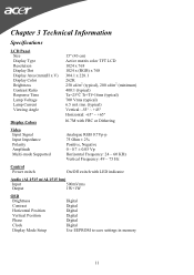
... Panel Size Display Type Resolution Display Dot Display Area (mm)(H x V) Display Color Brightness Contrast Ratio Response Time Lamp Voltage Lamp Current Viewing Angle 15" (43 cm) Active matrix color TFT LCD 1024 x 768 1024 x (RGB) x 768 304.1 x 228.1 262K 250 cd/m2 (... Vp Horizontal Frequency: 24 ~ 60 KHz Vertical Frequency: 49 ~ 75 Hz Control Power switch On/Off switch with LED indicator Audio (AL1515 m/AL1515 bm) Input 500mVrms Output 1W+1W OSD Brightness Contrast Horizontal Position Vertical Position Phase Clock Display Mode Setup Digital Digital Digital Digital Digital Digital Use...
... Panel Size Display Type Resolution Display Dot Display Area (mm)(H x V) Display Color Brightness Contrast Ratio Response Time Lamp Voltage Lamp Current Viewing Angle 15" (43 cm) Active matrix color TFT LCD 1024 x 768 1024 x (RGB) x 768 304.1 x 228.1 262K 250 cd/m2 (... Vp Horizontal Frequency: 24 ~ 60 KHz Vertical Frequency: 49 ~ 75 Hz Control Power switch On/Off switch with LED indicator Audio (AL1515 m/AL1515 bm) Input 500mVrms Output 1W+1W OSD Brightness Contrast Horizontal Position Vertical Position Phase Clock Display Mode Setup Digital Digital Digital Digital Digital Digital Use...
AL1515 User's Guide
Page 12
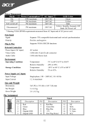
...and negative Supports VESA DDC2B functions External Connection Power Input (AC input) Video Cable Audio Cable AC socket 1.8M with 15-pin D-sub connector 1.8M with Stereo Jack Environment Operating Condition: Storage Condition: Temperature Relative Humidity Temperature Relative Humidity 5&#... Net Weight Gross Weight 345 (W) x 355 (H) x 149.7 (D) mm 3 ± 0.5 kg 3.9 ± 0.5 kg Pin Assignment 6 PIN 1 11 1 2 5 15 3 4 10 5 Description Red Green Blue Digital GND Digital GND Signal PIN Description 6 Red Rtn 7 Green Rtn 8 Blue Rtn 9 +5V 10 Hot Plug Detect PIN Description...
...and negative Supports VESA DDC2B functions External Connection Power Input (AC input) Video Cable Audio Cable AC socket 1.8M with 15-pin D-sub connector 1.8M with Stereo Jack Environment Operating Condition: Storage Condition: Temperature Relative Humidity Temperature Relative Humidity 5&#... Net Weight Gross Weight 345 (W) x 355 (H) x 149.7 (D) mm 3 ± 0.5 kg 3.9 ± 0.5 kg Pin Assignment 6 PIN 1 11 1 2 5 15 3 4 10 5 Description Red Green Blue Digital GND Digital GND Signal PIN Description 6 Red Rtn 7 Green Rtn 8 Blue Rtn 9 +5V 10 Hot Plug Detect PIN Description...
AL1515 User's Guide
Page 13
... 8 7 25 640x400 31.469 - 800 640 96 16 48 25.175 VGA-GRAPH 70.087 + 449 400 2 640x400 31.5 - 800 640 64 NEC PC9821 70.15 - 449 400 2 640X480 31.469 - 800 640 96 12 35 16 80 25.197 13 34 16 48 25.175 VESA-PAL 50.030 - 629...
... 8 7 25 640x400 31.469 - 800 640 96 16 48 25.175 VGA-GRAPH 70.087 + 449 400 2 640x400 31.5 - 800 640 64 NEC PC9821 70.15 - 449 400 2 640X480 31.469 - 800 640 96 12 35 16 80 25.197 13 34 16 48 25.175 VESA-PAL 50.030 - 629...
AL1515 User's Guide
Page 15
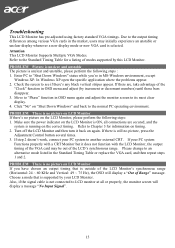
... is outside of the LCD Monitor's synchronous range (Horizontal: 24 ~ 60 KHz and Vertical: 49 ~ 75 Hz), the OSD will display a message "No Input Signal". 15 Please change to the normal PC operating environment. Choose a mode that is selected. Click "No" on LCD Monitor If there's no picture, press the Adjustment...
... is outside of the LCD Monitor's synchronous range (Horizontal: 24 ~ 60 KHz and Vertical: 49 ~ 75 Hz), the OSD will display a message "No Input Signal". 15 Please change to the normal PC operating environment. Choose a mode that is selected. Click "No" on LCD Monitor If there's no picture, press the Adjustment...

