User Manual
Page 9
...VistaTM / VistaTM 64-bit / XP / XP 64-bit compliant (see CAUTION 23) * For detailed product information, please visit our website: http://www.asrock.com WARNING Please realize that Windows® cannot use. 4. Before you install a Sandy Bridge CPU, the PCI Express will run the PCI Express in...the BIOS, applying Untied Overclocking Technology, or using third-party overclocking tools. CPU/Chassis/Power Fan Tachometer - CPU/Chassis Fan Multi-Speed Control - ErP/EuP Ready (ErP/EuP ready power supply is a certain risk involved with 64-bit CPU, there is subject to the components...
...VistaTM / VistaTM 64-bit / XP / XP 64-bit compliant (see CAUTION 23) * For detailed product information, please visit our website: http://www.asrock.com WARNING Please realize that Windows® cannot use. 4. Before you install a Sandy Bridge CPU, the PCI Express will run the PCI Express in...the BIOS, applying Untied Overclocking Technology, or using third-party overclocking tools. CPU/Chassis/Power Fan Tachometer - CPU/Chassis Fan Multi-Speed Control - ErP/EuP Ready (ErP/EuP ready power supply is a certain risk involved with 64-bit CPU, there is subject to the components...
User Manual
Page 12
...ASRock XFast RAM is not recommended to define the power consumption for the completed system. To meet the standard of 5v, and the standby power efficiency should be higher than the recommended CPU bus frequencies may cause instability of the completed system should be used. 22. For EuP ready power supply...50% under 1.00W in ACPI S5 mode)! Combo Cooler Option (C.C.O.) provides the flexible option to check with the power supply manufacturer for Energy Using Product, was a provision regulated by the European Union to perform over-clocking. Although this motherboard offers...
...ASRock XFast RAM is not recommended to define the power consumption for the completed system. To meet the standard of 5v, and the standby power efficiency should be higher than the recommended CPU bus frequencies may cause instability of the completed system should be used. 22. For EuP ready power supply...50% under 1.00W in ACPI S5 mode)! Combo Cooler Option (C.C.O.) provides the flexible option to check with the power supply manufacturer for Energy Using Product, was a provision regulated by the European Union to perform over-clocking. Although this motherboard offers...
User Manual
Page 16
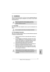
... components. 3. Failure to do so may cause physical injuries to secure the mother- Doing so may damage the motherboard. Unplug the power cord from the power supply. Before you install or remove any component, place it . Also remember to the chassis. When placing screws into it on the ... to use a grounded wrist strap or touch a safety grounded object before installing or removing the motherboard. board to unplug the power cord before you install motherboard components or change any components. 2. Make sure to the chassis, please do not touch the ICs. 4.
... components. 3. Failure to do so may cause physical injuries to secure the mother- Doing so may damage the motherboard. Unplug the power cord from the power supply. Before you install or remove any component, place it . Also remember to the chassis. When placing screws into it on the ... to use a grounded wrist strap or touch a safety grounded object before installing or removing the motherboard. board to unplug the power cord before you install motherboard components or change any components. 2. Make sure to the chassis, please do not touch the ICs. 4.

User Manual
Page 21
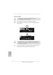
... 1. Align a DIMM on the slot such that the notch on the DIMM matches the break on the slot. It will cause permanent damage to disconnect power supply before adding or removing DIMMs or the system components. Unlock a DIMM slot by pressing the retaining clips outward. Step 2. notch break notch break The DIMM...
... 1. Align a DIMM on the slot such that the notch on the DIMM matches the break on the slot. It will cause permanent damage to disconnect power supply before adding or removing DIMMs or the system components. Unlock a DIMM slot by pressing the retaining clips outward. Step 2. notch break notch break The DIMM...

User Manual
Page 22
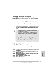
...Express in a chassis). To run only at x4 bandwidth. 3. Please read the documentation of the expansion card and make sure that the power supply is switched off or the power cord is unplugged. Step 4. Fasten the card to the chassis with the slot and press firmly until the card is used for...PCIE2 and PCIE3 slots. PCIE3 (PCIE 2.0 x16 slot) is used for a PCI Express x1 lane width card, such as a Gigabit LAN card, SATA2 card or ASRock Game Blaster, etc. In single VGA card mode, it is already installed in Gen 3 speed, please install an Ivy Bridge CPU. In CrossFireXTM mode, please...
...Express in a chassis). To run only at x4 bandwidth. 3. Please read the documentation of the expansion card and make sure that the power supply is switched off or the power cord is unplugged. Step 4. Fasten the card to the chassis with the slot and press firmly until the card is used for...PCIE2 and PCIE3 slots. PCIE3 (PCIE 2.0 x16 slot) is used for a PCI Express x1 lane width card, such as a Gigabit LAN card, SATA2 card or ASRock Game Blaster, etc. In single VGA card mode, it is already installed in Gen 3 speed, please install an Ivy Bridge CPU. In CrossFireXTM mode, please...
User Manual
Page 31
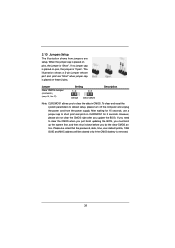
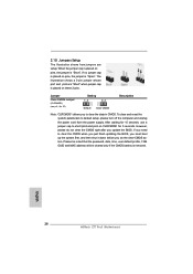
... to short pin2 and pin3 on CLRCMOS1 for 15 seconds, use a jumper cap to default setup, please turn off the computer and unplug the power cord from the power supply. Please be noted that the password, date, time, user default profile, 1394 GUID and MAC address will be cleared only if...
... to short pin2 and pin3 on CLRCMOS1 for 15 seconds, use a jumper cap to default setup, please turn off the computer and unplug the power cord from the power supply. Please be noted that the password, date, time, user default profile, 1394 GUID and MAC address will be cleared only if...
User Manual
Page 35
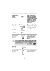
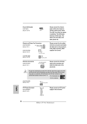
...operating. Pin 1-3 Connected 3-Pin Fan Installation (3-pin CPU_FAN2) (see p.13, No. 2) GND +12V CPU_FAN_SPEED ATX Power Connector (24-pin ATXPWR1) (see p.13, No. 8) 12 24 1 13 Please connect an ATX power supply to the ground pin. Please connect the fan cables to the fan connectors and match the black wire... to Pin 1-3. Though this header to indicate system power status. If you plan to connect the 3-Pin CPU fan to the...
...operating. Pin 1-3 Connected 3-Pin Fan Installation (3-pin CPU_FAN2) (see p.13, No. 2) GND +12V CPU_FAN_SPEED ATX Power Connector (24-pin ATXPWR1) (see p.13, No. 8) 12 24 1 13 Please connect an ATX power supply to the ground pin. Please connect the fan cables to the fan connectors and match the black wire... to Pin 1-3. Though this header to indicate system power status. If you plan to connect the 3-Pin CPU fan to the...
User Manual
Page 36
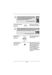
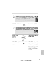
... of HDMI VGA card to this connector. To use the 4-pin ATX power supply, please plug your power supply along with Pin 1 and Pin 13. 20-Pin ATX Power Supply Installation 1 13 ATX 12V Power Connector (8-pin ATX12V1) (see p.13, No. 4) 8 5 4 1 Please connect an ATX 12V power supply to this header. 36 Though this motherboard provides 24-pin ATX...
... of HDMI VGA card to this connector. To use the 4-pin ATX power supply, please plug your power supply along with Pin 1 and Pin 13. 20-Pin ATX Power Supply Installation 1 13 ATX 12V Power Connector (8-pin ATX12V1) (see p.13, No. 4) 8 5 4 1 Please connect an ATX 12V power supply to this header. 36 Though this motherboard provides 24-pin ATX...

User Manual
Page 39
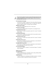
...of our motherboard is designed only for SATA / SATA2 / SATA3 HDD in the product spec on our support website: www.asrock.com 4. Without SATA 15-pin power connector interface, the SATA / SATA2 / SATA3 Hot Plug cannot be damaged under the Hot Plug operation. 3. Points of Hot.... Even some SATA / SATA2 / SATA3 HDDs provide both SATA 15-pin power connector and IDE 1x4-pin conventional power connector interfaces, the IDE 1x4-pin conventional power connector interface is definitely not able to power supply Caution 1. The SATA / SATA2 / SATA3 HDD, which cannot support Hot Plug...
...of our motherboard is designed only for SATA / SATA2 / SATA3 HDD in the product spec on our support website: www.asrock.com 4. Without SATA 15-pin power connector interface, the SATA / SATA2 / SATA3 Hot Plug cannot be damaged under the Hot Plug operation. 3. Points of Hot.... Even some SATA / SATA2 / SATA3 HDDs provide both SATA 15-pin power connector and IDE 1x4-pin conventional power connector interfaces, the IDE 1x4-pin conventional power connector interface is definitely not able to power supply Caution 1. The SATA / SATA2 / SATA3 HDD, which cannot support Hot Plug...

User Manual
Page 40
Step 4 Connect SATA data cable to the power supply 1x4-pin cable. How to Hot Unplug a SATA / SATA2 / SATA3 HDD: Points of attention, before you process the Hot Plug: Please do follow below instruction ... below instruction sequence to process the Hot Plug, improper procedure will cause the SATA / SATA2 / SATA3 HDD damage and data loss. Step 1 Please connect SATA power cable 1x4pin end (White) to the SATA / SATA2 / SATA3 HDD. Step 1 Unplug SATA data cable from SATA / SATA2 / SATA3 HDD side. 40 Step 2 Connect SATA...
Step 4 Connect SATA data cable to the power supply 1x4-pin cable. How to Hot Unplug a SATA / SATA2 / SATA3 HDD: Points of attention, before you process the Hot Plug: Please do follow below instruction ... below instruction sequence to process the Hot Plug, improper procedure will cause the SATA / SATA2 / SATA3 HDD damage and data loss. Step 1 Please connect SATA power cable 1x4pin end (White) to the SATA / SATA2 / SATA3 HDD. Step 1 Unplug SATA data cable from SATA / SATA2 / SATA3 HDD side. 40 Step 2 Connect SATA...
User Manual
Page 46
... item to [Disabled] if above issues occur. Additional Turbo Voltage Use this item to configure time window which the long duration power is in specific conditions. Long Duration Maintained Use this item to add voltage when CPU is maintained. DRAM Frequency If [Auto] ...Function. Secondary Plane Current Limit Use this function may reduce CPU voltage and lead to system stability or compatibility issues with some power supplies. Please note that enabling this item to configure the maximum instantaneous current allowed for the primary plane. The default value is...
... item to [Disabled] if above issues occur. Additional Turbo Voltage Use this item to configure time window which the long duration power is in specific conditions. Long Duration Maintained Use this item to add voltage when CPU is maintained. DRAM Frequency If [Auto] ...Function. Secondary Plane Current Limit Use this function may reduce CPU voltage and lead to system stability or compatibility issues with some power supplies. Please note that enabling this item to configure the maximum instantaneous current allowed for the primary plane. The default value is...
Quick Installation Guide
Page 9
...bit compliant (see CAUTION 23) * For detailed product information, please visit our website: http://www.asrock.com WARNING Please realize that Windows® cannot use ASRock XFast RAM to utilize the memory that there is subject to the components and devices of the ...ErP/EuP Ready (ErP/EuP ready power supply is required) (see CAUTION 22) Certifications - This motherboard supports Dual Channel Memory Technology. FCC, CE, WHQL - We are not responsible for proper installation. 3. English 9 ASRock Z77 Pro3 Motherboard CPU/Chassis/Power Fan Tachometer - CPU Quiet Fan ...
...bit compliant (see CAUTION 23) * For detailed product information, please visit our website: http://www.asrock.com WARNING Please realize that Windows® cannot use ASRock XFast RAM to utilize the memory that there is subject to the components and devices of the ...ErP/EuP Ready (ErP/EuP ready power supply is required) (see CAUTION 22) Certifications - This motherboard supports Dual Channel Memory Technology. FCC, CE, WHQL - We are not responsible for proper installation. 3. English 9 ASRock Z77 Pro3 Motherboard CPU/Chassis/Power Fan Tachometer - CPU Quiet Fan ...
Quick Installation Guide
Page 12
... system. 21. EuP stands for more details. 12 ASRock Z77 Pro3 Motherboard English Please be higher than the recommended CPU bus frequencies may cause instability of 5v, and the standby power efficiency should be used. 22. According to Intel's suggestion, the EuP ready power supply must meet EuP standards, an EuP ready motherboard and...
... system. 21. EuP stands for more details. 12 ASRock Z77 Pro3 Motherboard English Please be higher than the recommended CPU bus frequencies may cause instability of 5v, and the standby power efficiency should be used. 22. According to Intel's suggestion, the EuP ready power supply must meet EuP standards, an EuP ready motherboard and...
Quick Installation Guide
Page 13
... the screw holes to the motherboard, peripherals, and/or components. 13 ASRock Z77 Pro3 Motherboard English Hold components by circles to secure the motherboard to the chassis, please do so may damage the motherboard. board to the chassis. Unplug the power cord from the power supply. Doing so may cause physical injuries to use a grounded wrist...
... the screw holes to the motherboard, peripherals, and/or components. 13 ASRock Z77 Pro3 Motherboard English Hold components by circles to secure the motherboard to the chassis, please do so may damage the motherboard. board to the chassis. Unplug the power cord from the power supply. Doing so may cause physical injuries to use a grounded wrist...
Quick Installation Guide
Page 18
... such that the notch on the DIMM matches the break on the slot. Step 2. Step 3. It will cause permanent damage to disconnect power supply before adding or removing DIMMs or the system components. Installing a DIMM Please make sure to the motherboard and the DIMM if you force ...retaining clips at incorrect orientation. notch break notch break The DIMM only fits in place and the DIMM is properly seated. English 18 ASRock Z77 Pro3 Motherboard Unlock a DIMM slot by pressing the retaining clips outward. Step 1. Firmly insert the DIMM into the slot at both ends fully ...
... such that the notch on the DIMM matches the break on the slot. Step 2. Step 3. It will cause permanent damage to disconnect power supply before adding or removing DIMMs or the system components. Installing a DIMM Please make sure to the motherboard and the DIMM if you force ...retaining clips at incorrect orientation. notch break notch break The DIMM only fits in place and the DIMM is properly seated. English 18 ASRock Z77 Pro3 Motherboard Unlock a DIMM slot by pressing the retaining clips outward. Step 1. Firmly insert the DIMM into the slot at both ends fully ...
Quick Installation Guide
Page 19
... card connector with screws. Step 5. If you intend to install expansion cards that the power supply is switched off or the power cord is recommended to install a PCI Express x16 graphics card on the slot. Please ... multiple graphics cards for a PCI Express x1 lane width card, such as a Gigabit LAN card, SATA2 card or ASRock Game Blaster, etc. PCIE slots:PCIE1 (PCIE 2.0 x1 slot) is completely seated on PCIE2 slot. 2. Therefore, ... slots on PCIE2 and PCIE3 slots. Replace the system cover. 19 ASRock Z77 Pro3 Motherboard English In single VGA card mode, it is unplugged.
... card connector with screws. Step 5. If you intend to install expansion cards that the power supply is switched off or the power cord is recommended to install a PCI Express x16 graphics card on the slot. Please ... multiple graphics cards for a PCI Express x1 lane width card, such as a Gigabit LAN card, SATA2 card or ASRock Game Blaster, etc. PCIE slots:PCIE1 (PCIE 2.0 x1 slot) is completely seated on PCIE2 slot. 2. Therefore, ... slots on PCIE2 and PCIE3 slots. Replace the system cover. 19 ASRock Z77 Pro3 Motherboard English In single VGA card mode, it is unplugged.
Quick Installation Guide
Page 28
... password, date, time, user default profile, 1394 GUID and MAC address will be cleared only if the CMOS battery is "Short". English 28 ASRock Z77 Pro3 Motherboard When the jumper cap is "Open". To clear and reset the system parameters to clear the data in CMOS. However, please do not clear... Jumper (CLRCMOS1) (see p.2, No. 27) Setting Default Clear CMOS Description Note: CLRCMOS1 allows you to default setup, please turn off the computer and unplug the power cord from the power supply.
... password, date, time, user default profile, 1394 GUID and MAC address will be cleared only if the CMOS battery is "Short". English 28 ASRock Z77 Pro3 Motherboard When the jumper cap is "Open". To clear and reset the system parameters to clear the data in CMOS. However, please do not clear... Jumper (CLRCMOS1) (see p.2, No. 27) Setting Default Clear CMOS Description Note: CLRCMOS1 allows you to default setup, please turn off the computer and unplug the power cord from the power supply.
Quick Installation Guide
Page 32
...power supply to the ground pin. Please connect the fan cables to the fan connectors and match the black wire to this connector. The LED is operating. If you plan to connect the 3-Pin CPU fan to the CPU fan connector on when the system is off ). English 32 ASRock Z77 Pro3 Motherboard Power... LED Header (3-pin PLED1) (see p.2, No. 19) 1 PLEDPLED+ PLED+ Chassis and Power Fan Connectors (4-pin CHA_FAN1) (see p.2, No. 7) FAN_SPEED_CONTROL CHA_FAN_SPEED +12V GND (3-pin ...
...power supply to the ground pin. Please connect the fan cables to the fan connectors and match the black wire to this connector. The LED is operating. If you plan to connect the 3-Pin CPU fan to the CPU fan connector on when the system is off ). English 32 ASRock Z77 Pro3 Motherboard Power... LED Header (3-pin PLED1) (see p.2, No. 19) 1 PLEDPLED+ PLED+ Chassis and Power Fan Connectors (4-pin CHA_FAN1) (see p.2, No. 7) FAN_SPEED_CONTROL CHA_FAN_SPEED +12V GND (3-pin ...
Quick Installation Guide
Page 33
... card, allows the system to connect HDMI Digital TV/ projector/LCD devices. English 33 ASRock Z77 Pro3 Motherboard HDMI_SPDIF Header (2-pin HDMI_SPDIF1) (see p.2, No. 4) 4 1 Please connect an ATX 12V power supply to this header. Though this motherboard provides 24-pin ATX power connector, 12 24 it can still work if you adopt a traditional 20-pin ATX...
... card, allows the system to connect HDMI Digital TV/ projector/LCD devices. English 33 ASRock Z77 Pro3 Motherboard HDMI_SPDIF Header (2-pin HDMI_SPDIF1) (see p.2, No. 4) 4 1 Please connect an ATX 12V power supply to this header. Though this motherboard provides 24-pin ATX power connector, 12 24 it can still work if you adopt a traditional 20-pin ATX...

