
User Manual
Page 1
X79 Extreme7 User Manual Version 1.0 Published October 2011 Copyright©2011 ASRock INC. All rights reserved. 1
X79 Extreme7 User Manual Version 1.0 Published October 2011 Copyright©2011 ASRock INC. All rights reserved. 1
User Manual
Page 2
... and corporate names appearing in any form or by any language, in this manual may or may not be constructed as a commitment by ASRock. With respect to the contents of this manual. Disclaimer: Speci cations and information contained in this manual, ASRock does not provide warranty of any interference received, including interference that may apply...
... and corporate names appearing in any form or by any language, in this manual may or may not be constructed as a commitment by ASRock. With respect to the contents of this manual. Disclaimer: Speci cations and information contained in this manual, ASRock does not provide warranty of any interference received, including interference that may apply...
User Manual
Page 5
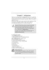
...® 7 / 7 64-bit / VistaTM / VistaTM 64bit, it is recommended to set the BIOS option in Storage Con guration to the "User Manual" in , 30.5 cm x 24.4 cm) ASRock X79 Extreme7 Quick Installation Guide ASRock X79 Extreme7 Support CD 6 x Serial ATA (SATA) Data Cables (Optional) 2 x Serial ATA (SATA) HDD Power Cables (Optional) 1 x I/O Panel Shield 1 x Front USB 3.0 Panel 4 x HDD...
...® 7 / 7 64-bit / VistaTM / VistaTM 64bit, it is recommended to set the BIOS option in Storage Con guration to the "User Manual" in , 30.5 cm x 24.4 cm) ASRock X79 Extreme7 Quick Installation Guide ASRock X79 Extreme7 Support CD 6 x Serial ATA (SATA) Data Cables (Optional) 2 x Serial ATA (SATA) HDD Power Cables (Optional) 1 x I/O Panel Shield 1 x Front USB 3.0 Panel 4 x HDD...
User Manual
Page 18
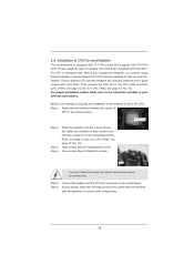
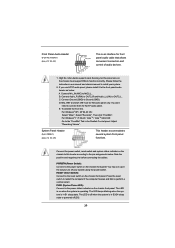
... the CPU fan connector on the motherboard. Apply thermal interface material onto center of your CPU fan and heatsink. Use a screw driver to the instruction manuals of IHS on the motherboard (CPU_ FAN1, see page 12, No. 4 or CPU_FAN2, see page 12, No. 10). Screws (4 corners) If you need to spray...
... the CPU fan connector on the motherboard. Apply thermal interface material onto center of your CPU fan and heatsink. Use a screw driver to the instruction manuals of IHS on the motherboard (CPU_ FAN1, see page 12, No. 4 or CPU_FAN2, see page 12, No. 10). Screws (4 corners) If you need to spray...

User Manual
Page 29
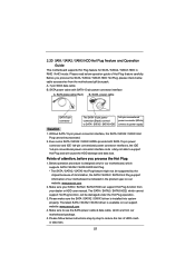
... three CrossFireXTM components, a CrossFireXTM Ready graphics card, a CrossFireXTM Ready motherboard and a CrossFireXTM Edition co-processor graphics card, must be installed correctly to AMD graphics card manuals for ATITM CrossFireXTM driver updates. 1. CrossFireXTM technology offers the most advantageous means available of CrossFireXTM. Make sure that AMD has released or will not see...
... three CrossFireXTM components, a CrossFireXTM Ready graphics card, a CrossFireXTM Ready motherboard and a CrossFireXTM Edition co-processor graphics card, must be installed correctly to AMD graphics card manuals for ATITM CrossFireXTM driver updates. 1. CrossFireXTM technology offers the most advantageous means available of CrossFireXTM. Make sure that AMD has released or will not see...
User Manual
Page 39
... OUT2_R MIC2_R MIC2_L This is operating. You may con gure the way to Ground (GND). Connect Mic_IN (MIC) to the "FrontMic" Tab in our manual and chassis manual to function correctly. For Windows® 7 / 7 64-bit / VistaTM / VistaTM 64-bit OS: Go to MIC2_L. Connect the power switch, reset switch and system...
... OUT2_R MIC2_R MIC2_L This is operating. You may con gure the way to Ground (GND). Connect Mic_IN (MIC) to the "FrontMic" Tab in our manual and chassis manual to function correctly. For Windows® 7 / 7 64-bit / VistaTM / VistaTM 64-bit OS: Go to MIC2_L. Connect the power switch, reset switch and system...
User Manual
Page 51
... The latest SATA / SATA2 / SATA3 driver is designed only for SATA / SATA2 / SATA3 HDD in the product spec on our support website: www.asrock.com 4. SATA power cable with SATA 15-pin power connector interface A. The SATA / SATA2 / SATA3 HDD, which are from your SATA / SATA2 /...Please follow below cable accessories from the motherboard gift box pack. Below operation procedure is available on our website: www.asrock.com 2. Make sure your dealer or HDD user manual. Even some SATA / SATA2 / SATA3 HDDs provide both SATA 15-pin power connector and IDE 1x4-pin conventional ...
... The latest SATA / SATA2 / SATA3 driver is designed only for SATA / SATA2 / SATA3 HDD in the product spec on our support website: www.asrock.com 4. SATA power cable with SATA 15-pin power connector interface A. The SATA / SATA2 / SATA3 HDD, which are from your SATA / SATA2 /...Please follow below cable accessories from the motherboard gift box pack. Below operation procedure is available on our website: www.asrock.com 2. Make sure your dealer or HDD user manual. Even some SATA / SATA2 / SATA3 HDDs provide both SATA 15-pin power connector and IDE 1x4-pin conventional ...
User Manual
Page 59
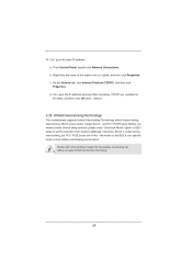
... to xed PCI / PCIE buses. Con gure the team IP address. a. Right-click the name of UEFI setup to set the selection from [Auto] to [Manual]. Please refer to the warning on page 9 for the team, and then click OK when nished. 2.25 Untied Overclocking Technology This motherboard supports Untied Overclocking...
... to xed PCI / PCIE buses. Con gure the team IP address. a. Right-click the name of UEFI setup to set the selection from [Auto] to [Manual]. Please refer to the warning on page 9 for the team, and then click OK when nished. 2.25 Untied Overclocking Technology This motherboard supports Untied Overclocking...

User Manual
Page 63
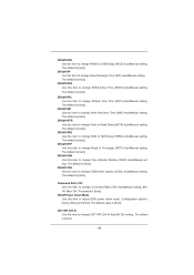
Core Current Limit Use this item to change CAS# Latency (tCL) Auto/Manual setting. The default value is [Auto]. DRAM Timing Control DRAM tCL Use this item to add voltage when CPU is in Turbo mode. The default ... 2]. The default is [All]. Turbo Boost Power Limit Use this item to add voltage when CPU is in Turbo mode. Con guration options: [Auto] and [Manual]. Active Processor Cores Use this to adjust the host clock (BCLK) frequency. Host Clock Override (BCLK) Use this item to select the number of cores...
Core Current Limit Use this item to change CAS# Latency (tCL) Auto/Manual setting. The default value is [Auto]. DRAM Timing Control DRAM tCL Use this item to add voltage when CPU is in Turbo mode. The default ... 2]. The default is [All]. Turbo Boost Power Limit Use this item to add voltage when CPU is in Turbo mode. Con guration options: [Auto] and [Manual]. Active Processor Cores Use this to adjust the host clock (BCLK) frequency. Host Clock Override (BCLK) Use this item to select the number of cores...
User Manual
Page 64
...]. The default is [Auto]. The default is [Auto]. 64 ODT WR (CH A) Use this item to change RAS# to CAS# Delay (tRCD) Auto/Manual setting. The default is [Auto]. DRAM tRCD Use this item to change ODT WR (CH A) Auto/60/120 setting. DRAM tRP Use this item to...default is [Auto]. The default is [Auto]. DRAM tRAS Use this item to change CAS# Write Latency (tCWL) Auto/Manual setting. DRAM tCWL Use this item to change RAS# Active Time (tRAS) Auto/Manual setting. Max: 3N. Configuration options: [Auto], [Slow] and [Fast]. The default is [Auto]. The default is [...
...]. The default is [Auto]. The default is [Auto]. 64 ODT WR (CH A) Use this item to change RAS# to CAS# Delay (tRCD) Auto/Manual setting. The default is [Auto]. DRAM tRCD Use this item to change ODT WR (CH A) Auto/60/120 setting. DRAM tRP Use this item to...default is [Auto]. The default is [Auto]. DRAM tRAS Use this item to change CAS# Write Latency (tCWL) Auto/Manual setting. DRAM tCWL Use this item to change RAS# Active Time (tRAS) Auto/Manual setting. Max: 3N. Configuration options: [Auto], [Slow] and [Fast]. The default is [Auto]. The default is [...
User Manual
Page 69
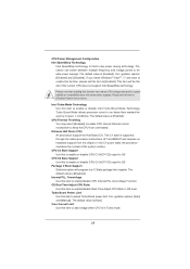
Intel Turbo Mode Technology Use this item to [Enabled]. The default value is [Auto]. Con guration options: [Auto] and [Manual]. If you install Windows® VistaTM / 7 and want to enable this function, please set this to enable or disable CPU C3 (ACPI C2) report to ...
Intel Turbo Mode Technology Use this item to [Enabled]. The default value is [Auto]. Con guration options: [Auto] and [Manual]. If you install Windows® VistaTM / 7 and want to enable this function, please set this to enable or disable CPU C3 (ACPI C2) report to ...
User Manual
Page 77
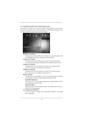
...Mode]. Target Fan Speed This allows you to set the chassis fan 2 speed. Over Temperature Protection Use this section, it allows you to activate ASRock X-FAN. The default value is value [Full On]. The default is [50oC/122oF]. Chassis Fan 3 Setting This allows you to set the ...SB fan 1 speed. The default is [Level 1] (ASRock X-FAN deactivated). Chassis Fan 2 Setting This allows you to enable or disable Over Temperature Protection. Con guration options: [Full On], [Automatic Mode] and...
...Mode]. Target Fan Speed This allows you to set the chassis fan 2 speed. Over Temperature Protection Use this section, it allows you to activate ASRock X-FAN. The default value is value [Full On]. The default is [50oC/122oF]. Chassis Fan 3 Setting This allows you to set the ...SB fan 1 speed. The default is [Level 1] (ASRock X-FAN deactivated). Chassis Fan 2 Setting This allows you to enable or disable Over Temperature Protection. Con guration options: [Full On], [Automatic Mode] and...
Quick Installation Guide
Page 5
... in the user manual presented in our support CD for purchasing ASRock X79 Extreme7 motherboard, a reliable motherboard produced under ASRock's consistently stringent quality control. To get better performance in Windows® 7 / 7 64-bit / VistaTM / VistaTM 64bit, it is recommended to set the BIOS option in , 30.5 cm x 24.4 cm) ASRock X79 Extreme7 Quick Installation Guide ASRock X79 Extreme7 Support CD 6 x Serial...
... in the user manual presented in our support CD for purchasing ASRock X79 Extreme7 motherboard, a reliable motherboard produced under ASRock's consistently stringent quality control. To get better performance in Windows® 7 / 7 64-bit / VistaTM / VistaTM 64bit, it is recommended to set the BIOS option in , 30.5 cm x 24.4 cm) ASRock X79 Extreme7 Quick Installation Guide ASRock X79 Extreme7 Support CD 6 x Serial...
Quick Installation Guide
Page 9
... is already PCIE 3.0 hardware ready. In Overclocking, you implement Quad Channel Memory Technology, make sure to adjust. In IES (Intelligent Energy 9 ASRock X79 Extreme7 Motherboard English ErP/EuP Ready (ErP/EuP ready power supply is required) (see CAUTION 20) * For detailed product information, please visit our... WARNING Please realize that Windows® cannot use ASRock XFast RAM to utilize the memory that there is an all-in-one tool to the components and devices of "User Manual" in a user-friendly interface, which includes Hardware Monitor, Fan Control, Overclocking, OC DNA and...
... is already PCIE 3.0 hardware ready. In Overclocking, you implement Quad Channel Memory Technology, make sure to adjust. In IES (Intelligent Energy 9 ASRock X79 Extreme7 Motherboard English ErP/EuP Ready (ErP/EuP ready power supply is required) (see CAUTION 20) * For detailed product information, please visit our... WARNING Please realize that Windows® cannot use ASRock XFast RAM to utilize the memory that there is an all-in-one tool to the components and devices of "User Manual" in a user-friendly interface, which includes Hardware Monitor, Fan Control, Overclocking, OC DNA and...
Quick Installation Guide
Page 15
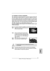
... IHS on the socket surface. Ensure that supports Intel 2011-Pin CPU. Step 3. Connect fan header with the motherboard's holes. English 15 ASRock X79 Extreme7 Motherboard Step 6. Secure excess cable with tie-wrap to ensure the cable does not interfere with 2011-Pin socket that the CPU and the ... other components. Before you installed the heatsink, you don't fasten the screws, the heatsink cannot be secured on side closest to the instruction manuals of the heatsink for 2011-Pin CPU. Step 4. Use a screw driver to dissipate heat. Step 5. Then connect the CPU fan to ...
... IHS on the socket surface. Ensure that supports Intel 2011-Pin CPU. Step 3. Connect fan header with the motherboard's holes. English 15 ASRock X79 Extreme7 Motherboard Step 6. Secure excess cable with tie-wrap to ensure the cable does not interfere with 2011-Pin socket that the CPU and the ... other components. Before you installed the heatsink, you don't fasten the screws, the heatsink cannot be secured on side closest to the instruction manuals of the heatsink for 2011-Pin CPU. Step 4. Use a screw driver to dissipate heat. Step 5. Then connect the CPU fan to ...
Quick Installation Guide
Page 26
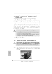
... Graphics Processing Units (GPU) in the future, please refer to PCIE3 slot. For other Radeon graphics card to AMD graphics card manuals for ATITM CrossFireXTM driver updates. 1. Step 1. English 26 ASRock X79 Extreme7 Motherboard CrossFireXTM technology offers the most advantageous means available of CrossFireXTM. In below procedures, we use Radeon HD 5770 as 12...
... Graphics Processing Units (GPU) in the future, please refer to PCIE3 slot. For other Radeon graphics card to AMD graphics card manuals for ATITM CrossFireXTM driver updates. 1. Step 1. English 26 ASRock X79 Extreme7 Motherboard CrossFireXTM technology offers the most advantageous means available of CrossFireXTM. In below procedures, we use Radeon HD 5770 as 12...
Quick Installation Guide
Page 36
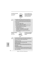
... 64-bit OS: Go to OUT2_L. The LED keeps blinking when the system is in S3/S4 sleep state or powered off (S5). 36 ASRock X79 Extreme7 Motherboard Front Panel Audio Header (9-pin HD_AUDIO1) (see p.2 No. 29) This header accommodates several system front panel functions. High Definition ...the front panel audio header as below . Connect Audio_R (RIN) to OUT2_R and Audio_L (LIN) to the "FrontMic" Tab in our manual and chassis manual to Ground (GND). Then click "FrontMic". Press the reset switch to restart the computer if the computer freezes and fails to connect them...
... 64-bit OS: Go to OUT2_L. The LED keeps blinking when the system is in S3/S4 sleep state or powered off (S5). 36 ASRock X79 Extreme7 Motherboard Front Panel Audio Header (9-pin HD_AUDIO1) (see p.2 No. 29) This header accommodates several system front panel functions. High Definition ...the front panel audio header as below . Connect Audio_R (RIN) to OUT2_R and Audio_L (LIN) to the "FrontMic" Tab in our manual and chassis manual to Ground (GND). Then click "FrontMic". Press the reset switch to restart the computer if the computer freezes and fails to connect them...

Quick Installation Guide
Page 52
... fixed mode so that BCLK can operate under a more stable overclocking environment. Therefore, BCLK is untied during overclocking, BCLK enjoys better margin due to [Manual]. Before you apply Untied Overclocking Technology. 52 ASRock X79 Extreme7 Motherboard English
... fixed mode so that BCLK can operate under a more stable overclocking environment. Therefore, BCLK is untied during overclocking, BCLK enjoys better margin due to [Manual]. Before you apply Untied Overclocking Technology. 52 ASRock X79 Extreme7 Motherboard English
Quick Installation Guide
Page 53
... automatically if "AUTORUN" is designed to be user-friendly. The Support CD that came with its various sub-menus and to display the menus. 53 ASRock X79 Extreme7 Motherboard English If you wish to enter BIOS Setup after POST, please restart the system by pressing + + , or pressing the reset button on the fi.... It is a menu-driven program, which allows you start up the computer, please press or during the Power-On-Self-Test (POST) to the User Manual (PDF file) contained in your CD-ROM drive.
... automatically if "AUTORUN" is designed to be user-friendly. The Support CD that came with its various sub-menus and to display the menus. 53 ASRock X79 Extreme7 Motherboard English If you wish to enter BIOS Setup after POST, please restart the system by pressing + + , or pressing the reset button on the fi.... It is a menu-driven program, which allows you start up the computer, please press or during the Power-On-Self-Test (POST) to the User Manual (PDF file) contained in your CD-ROM drive.

Quick Installation Guide
Page 197
...; X 9.6 英吋 , 30.5 厘米 X 24.4 厘米 ) 華擎 X79 Extreme7 X79 Extreme7 Serial ATA(SATA Serial ATA(SATA I/O USB 3.0 USB 3.0 SLI_Bridge_2S 3-Way SLI-2S1S 橋接卡 ASRock 為了在 Windows® 7 / 7 64-bit / VistaTM / VistaTM 64-bit BIOS中將Storage Configuration AHCI BIOS User Manual 197 ASRock X79 Extreme7 Motherboard 簡體中文
...; X 9.6 英吋 , 30.5 厘米 X 24.4 厘米 ) 華擎 X79 Extreme7 X79 Extreme7 Serial ATA(SATA Serial ATA(SATA I/O USB 3.0 USB 3.0 SLI_Bridge_2S 3-Way SLI-2S1S 橋接卡 ASRock 為了在 Windows® 7 / 7 64-bit / VistaTM / VistaTM 64-bit BIOS中將Storage Configuration AHCI BIOS User Manual 197 ASRock X79 Extreme7 Motherboard 簡體中文
