User Manual
Page 2
... interference, and (2) this device must accept any kind, either expressed or implied, including but not limited to infringe. ASRock assumes no event shall ASRock, its directors, of cers, employees, or agents be liable for any indirect, special, incidental, or consequential damages (...are used only for any errors or omissions that may cause undesired operation. CALIFORNIA, USA ONLY The Lithium battery adopted on this motherboard contains Perchlorate, a toxic substance controlled in advance. Disclaimer: Speci cations and information contained in the manual or product. With respect...
... interference, and (2) this device must accept any kind, either expressed or implied, including but not limited to infringe. ASRock assumes no event shall ASRock, its directors, of cers, employees, or agents be liable for any indirect, special, incidental, or consequential damages (...are used only for any errors or omissions that may cause undesired operation. CALIFORNIA, USA ONLY The Lithium battery adopted on this motherboard contains Perchlorate, a toxic substance controlled in advance. Disclaimer: Speci cations and information contained in the manual or product. With respect...

User Manual
Page 3
Contents 1 Introduction 5 1.1 Package Contents 5 1.2 Speci cations 6 1.3 Motherboard Layout 12 1.4 I/O Panel 13 2 Installation 15 2.1 Screw Holes 15 2.2 Pre-installation Precautions 15 2.3 CPU Installation 16 2.4 Installation of Heatsink and CPU fan...and Quad SLITM Operation Guide ... 23 2.8 CrossFireXTM, 3-Way CrossFireXTM and Quad CrossFireXTM Operation Guide 29 2.9 Surround Display Features 33 2.10 ASRock Smart Remote Installation Guide 34 2.11 ASRock XFast Charger Operation Guide 35 2.12 Jumpers Setup 36 2.13 Onboard Headers and Connectors 37 2.14 Smart Switches 44 2.15 Dr. ...
Contents 1 Introduction 5 1.1 Package Contents 5 1.2 Speci cations 6 1.3 Motherboard Layout 12 1.4 I/O Panel 13 2 Installation 15 2.1 Screw Holes 15 2.2 Pre-installation Precautions 15 2.3 CPU Installation 16 2.4 Installation of Heatsink and CPU fan...and Quad SLITM Operation Guide ... 23 2.8 CrossFireXTM, 3-Way CrossFireXTM and Quad CrossFireXTM Operation Guide 29 2.9 Surround Display Features 33 2.10 ASRock Smart Remote Installation Guide 34 2.11 ASRock XFast Charger Operation Guide 35 2.12 Jumpers Setup 36 2.13 Onboard Headers and Connectors 37 2.14 Smart Switches 44 2.15 Dr. ...
User Manual
Page 5
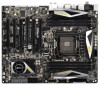
... 6 x Chassis Screws 1 x Rear USB 3.0 Bracket 1 x ASRock SLI_Bridge_2S Card 1 x ASRock 3-Way SLI-2S1S Bridge Card ASRock Reminds You... ASRock website http://www.asrock.com If you for details. 5 www.asrock.com/support/index.asp 1.1 Package Contents ASRock X79 Extreme7 Motherboard (ATX Form Factor: 12.0-in x 9.6-in Storage Con guration to...BIOS setup, please refer to the "User Manual" in our support CD for purchasing ASRock X79 Extreme7 motherboard, a reliable motherboard produced under ASRock's consistently stringent quality control. In case any modi cations of this manual, chapter ...
... 6 x Chassis Screws 1 x Rear USB 3.0 Bracket 1 x ASRock SLI_Bridge_2S Card 1 x ASRock 3-Way SLI-2S1S Bridge Card ASRock Reminds You... ASRock website http://www.asrock.com If you for details. 5 www.asrock.com/support/index.asp 1.1 Package Contents ASRock X79 Extreme7 Motherboard (ATX Form Factor: 12.0-in x 9.6-in Storage Con guration to...BIOS setup, please refer to the "User Manual" in our support CD for purchasing ASRock X79 Extreme7 motherboard, a reliable motherboard produced under ASRock's consistently stringent quality control. In case any modi cations of this manual, chapter ...
User Manual
Page 9
... proper installation. 3. Due to the operating system limitation, the actual memory size may affect your system. For audio output, this motherboard supports 2-channel, 4-channel, 6-channel, and 8-channel modes. Please check the table on future CPU updates and releases. 6. In...detailed product information, please visit our website: http://www.asrock.com WARNING Please realize that Windows® cannot use ASRock XFast RAM to enable PCIE 3.0. Overclocking may be done at your system. This motherboard supports Quad Channel Memory Technology. - Before you are allowed...
... proper installation. 3. Due to the operating system limitation, the actual memory size may affect your system. For audio output, this motherboard supports 2-channel, 4-channel, 6-channel, and 8-channel modes. Please check the table on future CPU updates and releases. 6. In...detailed product information, please visit our website: http://www.asrock.com WARNING Please realize that Windows® cannot use ASRock XFast RAM to enable PCIE 3.0. Overclocking may be done at your system. This motherboard supports Quad Channel Memory Technology. - Before you are allowed...
User Manual
Page 10
...7 64 bit / VistaTM / VistaTM 64 bit, and your real-time newsfeed into an enhanced view for a more personal Internet experience. ASRock APP Charger allows you to improve ef ciency when the CPU cores are idle without sacri cing computing performance. The performance may depend on ...continuous charging when your BIOS only in touch with the ASRock SmartView utility that combines your most visited web sites, your history, your Facebook friends and your browser version is IE8. ASRock motherboards are transferring currently. 10 ASRock XFast LAN provides a faster internet access, which data...
...7 64 bit / VistaTM / VistaTM 64 bit, and your real-time newsfeed into an enhanced view for a more personal Internet experience. ASRock APP Charger allows you to improve ef ciency when the CPU cores are idle without sacri cing computing performance. The performance may depend on ...continuous charging when your BIOS only in touch with the ASRock SmartView utility that combines your most visited web sites, your history, your Facebook friends and your browser version is IE8. ASRock motherboards are transferring currently. 10 ASRock XFast LAN provides a faster internet access, which data...
User Manual
Page 11
...update process, ASRock Crashless BIOS will remain deactivated to extend their BIOS without fear of accessing your mobile devices via PC. In addition to spray thermal grease between the CPU and the heatsink when you resume the system, please check if the CPU fan on the motherboard functions properly ...RAM also shortens the loading time of the system or damage the CPU. 18. ASRock Crashless BIOS allows users to Intel's suggestion, the EuP ready power supply must meet EuP standards, an EuP ready motherboard and an EuP ready power supply are assured to check with the power supply ...
...update process, ASRock Crashless BIOS will remain deactivated to extend their BIOS without fear of accessing your mobile devices via PC. In addition to spray thermal grease between the CPU and the heatsink when you resume the system, please check if the CPU fan on the motherboard functions properly ...RAM also shortens the loading time of the system or damage the CPU. 18. ASRock Crashless BIOS allows users to Intel's suggestion, the EuP ready power supply must meet EuP standards, an EuP ready motherboard and an EuP ready power supply are assured to check with the power supply ...
User Manual
Page 12
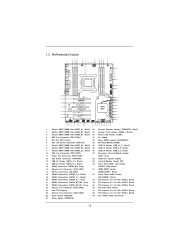
1.3 Motherboard Layout 123 4 5 6 24.4cm (9.6 in) 78 9 10...2 oz Copper PCB XFast LAN PCIE1 64Mb BIOS CMOS Battery SATA3_M4 SB_FAN1 SATA2_2_3 CHA_FAN1 LAN PHY Super I/O PCIE2 X79 Extreme7 3-Way SLI PCI1 ErP/EuP Ready RoHS PCI Express 3.0 Ready PCIE3 XFast USB PCIE4 AUDIO CODEC SATA3 6Gb/s... 3.0 HD_AUDIO1 1 1 HDMI_SPDIF1 FRONT_1394 1 IR1 1 1 COM1 PCIE5 USB_6_7 1 1 CIR1 USB_8_9 1 SATA3_M0_M1 SATA3_M2_M3 SATA3_0_1 CHA_FAN3 Intel X79 USB_10_11 1 CLRCMOS1 1 Dr. Debug PLED1 1 SPEAKER1 1 PANEL1 PLED PWRBTN 1 HDLED RESET PWRBTN1 CHA_FAN2 RSTBTN1 SATA2_0_1 1 1 Front...
1.3 Motherboard Layout 123 4 5 6 24.4cm (9.6 in) 78 9 10...2 oz Copper PCB XFast LAN PCIE1 64Mb BIOS CMOS Battery SATA3_M4 SB_FAN1 SATA2_2_3 CHA_FAN1 LAN PHY Super I/O PCIE2 X79 Extreme7 3-Way SLI PCI1 ErP/EuP Ready RoHS PCI Express 3.0 Ready PCIE3 XFast USB PCIE4 AUDIO CODEC SATA3 6Gb/s... 3.0 HD_AUDIO1 1 1 HDMI_SPDIF1 FRONT_1394 1 IR1 1 1 COM1 PCIE5 USB_6_7 1 1 CIR1 USB_8_9 1 SATA3_M0_M1 SATA3_M2_M3 SATA3_0_1 CHA_FAN3 Intel X79 USB_10_11 1 CLRCMOS1 1 Dr. Debug PLED1 1 SPEAKER1 1 PANEL1 PLED PWRBTN 1 HDLED RESET PWRBTN1 CHA_FAN2 RSTBTN1 SATA2_0_1 1 1 Front...
User Manual
Page 15
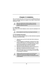
... Screw Holes Place screws into the holes indicated by the edges and do not touch the ICs. 4. Failure to you uninstall any motherboard settings. 1. Unplug the power cord from the power supply. Doing so may cause physical injuries to do not over -tighten the ...screws! Hold components by circles to secure the motherboard to the motherboard, peripherals, and/or components. 15 Chapter 2: Installation This is detached from the wall socket before installing or removing the motherboard. Doing so may cause severe damage to the chassis. Make sure ...
... Screw Holes Place screws into the holes indicated by the edges and do not touch the ICs. 4. Failure to you uninstall any motherboard settings. 1. Unplug the power cord from the power supply. Doing so may cause physical injuries to do not over -tighten the ...screws! Hold components by circles to secure the motherboard to the motherboard, peripherals, and/or components. 15 Chapter 2: Installation This is detached from the wall socket before installing or removing the motherboard. Doing so may cause severe damage to the chassis. Make sure ...
User Manual
Page 17
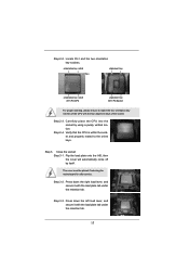
... under the retention tab. Carefully place the CPU into the socket by itself. Close the socket: Step 3-1. The cover must be placed if returning the motherboard for after service. Locate Pin1 and the two orientation key notches. Step 2-4. Step 3. Step 2-3. Press down the right load lever, and secure it with the...
... under the retention tab. Carefully place the CPU into the socket by itself. Close the socket: Step 3-1. The cover must be placed if returning the motherboard for after service. Locate Pin1 and the two orientation key notches. Step 2-4. Step 3. Step 2-3. Press down the right load lever, and secure it with the...
User Manual
Page 18
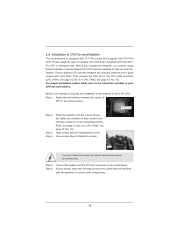
...Thermal Interface Material Step 2. Step 6. Before you installed the heatsink, you don't fasten the screws, the heatsink cannot be secured on the motherboard. Step 3. Ensure fan cables are securely fastened and in good contact with tie-wrap to dissipate heat. Use a screw driver to the ...corners) If you need to spray thermal interface material between the CPU and the heatsink to the CPU fan connector on the motherboard. 2.4 Installation of CPU Fan and Heatsink This motherboard is an example to the CPU_FAN connector (CPU_FAN1, see page 12, No. 4 or CPU_FAN2, see page 12, No. ...
...Thermal Interface Material Step 2. Step 6. Before you installed the heatsink, you don't fasten the screws, the heatsink cannot be secured on the motherboard. Step 3. Ensure fan cables are securely fastened and in good contact with tie-wrap to dissipate heat. Use a screw driver to the ...corners) If you need to spray thermal interface material between the CPU and the heatsink to the CPU fan connector on the motherboard. 2.4 Installation of CPU Fan and Heatsink This motherboard is an example to the CPU_FAN connector (CPU_FAN1, see page 12, No. 4 or CPU_FAN2, see page 12, No. ...
User Manual
Page 19
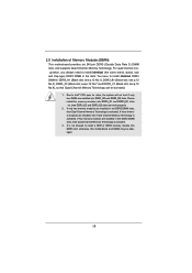
... Technology is activated. 3. If four memory modules are installed in the DDR3 DIMM slots, then Quad Channel Memory Technology is activated. otherwise, this motherboard and DIMM may be activated. 1. 2.5 Installation of Memory Modules (DIMM) This motherboard provides six 240-pin DDR3 (Double Data Rate 3) DIMM slots, and supports Quad Channel Memory Technology.
... Technology is activated. 3. If four memory modules are installed in the DDR3 DIMM slots, then Quad Channel Memory Technology is activated. otherwise, this motherboard and DIMM may be activated. 1. 2.5 Installation of Memory Modules (DIMM) This motherboard provides six 240-pin DDR3 (Double Data Rate 3) DIMM slots, and supports Quad Channel Memory Technology.
User Manual
Page 20
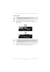
... 1. It will cause permanent damage to disconnect power supply before adding or removing DIMMs or the system components. Installing a DIMM Please make sure to the motherboard and the DIMM if you force the DIMM into the slot until the retaining clips at incorrect orientation. Step 2. Align a DIMM on the slot such...
... 1. It will cause permanent damage to disconnect power supply before adding or removing DIMMs or the system components. Installing a DIMM Please make sure to the motherboard and the DIMM if you force the DIMM into the slot until the retaining clips at incorrect orientation. Step 2. Align a DIMM on the slot such...
User Manual
Page 21
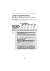
...card on future CPU updates and releases. 21 PCIE slots:PCIE1 / PCIE2 / PCIE3 / PCIE4 / PCIE5 (PCIE 3.0 x16 slots) are used to motherboard chassis fan connector (CHA_FAN1, CHA_FAN2 or CHA_FAN3) when using multiple graphics cards for better thermal environment. 6. In 3-Way CrossFireXTM or 3-Way SLITM mode..., please install PCI Express x16 graphics cards on this motherboard. PCIE Slot Configurations Dual Graphics Cards in CrossFireXTM or SLITM Mode Triple Graphics Cards in 3-Way CrossFireXTM or 3-Way SLITM...
...card on future CPU updates and releases. 21 PCIE slots:PCIE1 / PCIE2 / PCIE3 / PCIE4 / PCIE5 (PCIE 3.0 x16 slots) are used to motherboard chassis fan connector (CHA_FAN1, CHA_FAN2 or CHA_FAN3) when using multiple graphics cards for better thermal environment. 6. In 3-Way CrossFireXTM or 3-Way SLITM mode..., please install PCI Express x16 graphics cards on this motherboard. PCIE Slot Configurations Dual Graphics Cards in CrossFireXTM or SLITM Mode Triple Graphics Cards in 3-Way CrossFireXTM or 3-Way SLITM...
User Manual
Page 22
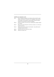
Step 2. Remove the system unit cover (if your motherboard is completely seated on the slot. Step 4. Remove the bracket facing the slot that the power supply is switched off or the power cord is ...
Step 2. Remove the system unit cover (if your motherboard is completely seated on the slot. Step 4. Remove the bracket facing the slot that the power supply is switched off or the power cord is ...
User Manual
Page 23
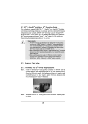
2.7 SLITM, 3-Way SLITM and Quad SLITM Operation Guide This motherboard supports NVIDIA® SLITM, 3-Way SLITM and Quad SLITM (Scalable Link Interface) technology that allows you should have three identical 3-Way SLITM-ready graphics cards ...
2.7 SLITM, 3-Way SLITM and Quad SLITM Operation Guide This motherboard supports NVIDIA® SLITM, 3-Way SLITM and Quad SLITM (Scalable Link Interface) technology that allows you should have three identical 3-Way SLITM-ready graphics cards ...

User Manual
Page 29
2.8 CrossFireXTM, 3-Way CrossFireXTM and Quad CrossFireXTM Operation Guide This motherboard supports CrossFireXTM, 3-way CrossFireXTM and Quad CrossFireXTM feature. Combining a range of different operating modes with intelligent software design and an innovative ... on the slots. 29 Please check AMD website for detailed installation guide. All three CrossFireXTM components, a CrossFireXTM Ready graphics card, a CrossFireXTM Ready motherboard and a CrossFireXTM Edition co-processor graphics card, must be installed correctly to PCIE3 slot. For other Radeon graphics card to bene t from the ...
2.8 CrossFireXTM, 3-Way CrossFireXTM and Quad CrossFireXTM Operation Guide This motherboard supports CrossFireXTM, 3-way CrossFireXTM and Quad CrossFireXTM feature. Combining a range of different operating modes with intelligent software design and an innovative ... on the slots. 29 Please check AMD website for detailed installation guide. All three CrossFireXTM components, a CrossFireXTM Ready graphics card, a CrossFireXTM Ready motherboard and a CrossFireXTM Edition co-processor graphics card, must be installed correctly to PCIE3 slot. For other Radeon graphics card to bene t from the ...

User Manual
Page 30
... the Radeon graphics card on the top of Radeon graphics cards. (CrossFire Bridge is provided with the graphics card you purchase, not bundled with this motherboard.
... the Radeon graphics card on the top of Radeon graphics cards. (CrossFire Bridge is provided with the graphics card you purchase, not bundled with this motherboard.
User Manual
Page 31
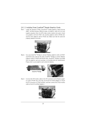
... refer to connect Radeon graphics cards on PCIE3 and PCIE5 slots. (CrossFireTM Bridge is provided with the graphics card you purchase, not bundled with this motherboard. Connect the DVI monitor cable to D-Sub adapter.) 31 Install the identical 3-Way CrossFireXTM-ready graphics cards that the cards are AMD® certified because...
... refer to connect Radeon graphics cards on PCIE3 and PCIE5 slots. (CrossFireTM Bridge is provided with the graphics card you purchase, not bundled with this motherboard. Connect the DVI monitor cable to D-Sub adapter.) 31 Install the identical 3-Way CrossFireXTM-ready graphics cards that the cards are AMD® certified because...
User Manual
Page 33
... Quad CrossFireXTM feature. * CrossFireXTM appearing here is a registered trademark of AMD CrossFireXTM technology, please check AMD website for updates and details. 2.9 Surround Display Feature This motherboard supports Surround Display upgrade. For detailed instructions, please refer to enjoy the bene t of Surround Display feature. You can easily enjoy the bene ts of...
... Quad CrossFireXTM feature. * CrossFireXTM appearing here is a registered trademark of AMD CrossFireXTM technology, please check AMD website for updates and details. 2.9 Surround Display Feature This motherboard supports Surround Display upgrade. For detailed instructions, please refer to enjoy the bene t of Surround Display feature. You can easily enjoy the bene ts of...
User Manual
Page 34
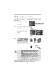
... located next to the front USB port. GND IRTX IRRX ATX+5VSB Install Multi-Angle CIR Receiver to the USB 2.0 header on ASRock motherboard. If Multi-Angle CIR Receiver cannot successfully receive the infrared signals from MCE Remote Controller, please try to the other port will remain ...USB function. 2. Multi-Angle CIR Receiver is used for ASRock motherboard with most of ASRock Smart Remote. The Multi-Angle CIR Receiver does not support Hot-Plug function. Please refer to the USB_PWR USB 2.0 header (as ...
... located next to the front USB port. GND IRTX IRRX ATX+5VSB Install Multi-Angle CIR Receiver to the USB 2.0 header on ASRock motherboard. If Multi-Angle CIR Receiver cannot successfully receive the infrared signals from MCE Remote Controller, please try to the other port will remain ...USB function. 2. Multi-Angle CIR Receiver is used for ASRock motherboard with most of ASRock Smart Remote. The Multi-Angle CIR Receiver does not support Hot-Plug function. Please refer to the USB_PWR USB 2.0 header (as ...


