
User Manual
Page 3
... the operating instructions. • The system was dropped or the cabinet is important that you read the following technical problems with ambient temperatures between 0o C and 40o C. • If you use • Do not walk on the power cord or allow anything to products (including HDD, ODD, memory and warranty seal) that the total ampere rating of the devices plugged...
... the operating instructions. • The system was dropped or the cabinet is important that you read the following technical problems with ambient temperatures between 0o C and 40o C. • If you use • Do not walk on the power cord or allow anything to products (including HDD, ODD, memory and warranty seal) that the total ampere rating of the devices plugged...

User Manual
Page 5
Contents 1 Introduction 7 1.1 Package Contents 7 1.2 Specifications 8 1.3 System Motherboard Components 9 1.4 Rear Panel Connections 11 1.5 System Chassis 12 1.6 Remote Controller 13 2 Opening the chassis 14 3 Reinstalling the ODD/HDD 15 4 Reinstalling the DIMMs 16 5 Reinstalling the CPU 17 6 Reinstalling the MXM card 18 7 Driver Installation 19 8 UTILITY MEMU 20 8.1 Instant Boot 20 8.1.1 Introduction 20 8.1.2 Installation 21 8.2 ASRock OC Tuner 23 8.2.1 Introduction 23 8.2.2 Installation 23 8.3 CyberLink DVD Suite free bundle (Trial version, including PowerDVD, ...
Contents 1 Introduction 7 1.1 Package Contents 7 1.2 Specifications 8 1.3 System Motherboard Components 9 1.4 Rear Panel Connections 11 1.5 System Chassis 12 1.6 Remote Controller 13 2 Opening the chassis 14 3 Reinstalling the ODD/HDD 15 4 Reinstalling the DIMMs 16 5 Reinstalling the CPU 17 6 Reinstalling the MXM card 18 7 Driver Installation 19 8 UTILITY MEMU 20 8.1 Instant Boot 20 8.1.1 Introduction 20 8.1.2 Installation 21 8.2 ASRock OC Tuner 23 8.2.1 Introduction 23 8.2.2 Installation 23 8.3 CyberLink DVD Suite free bundle (Trial version, including PowerDVD, ...

User Manual
Page 6
9.4.2 Chipset Configuration 43 9.4.3 ACPI Configuration 44 9.4.4 Storage Configuration 45 9.4.5 USB Configuration 46 9.5 Hardware Health Event Monitoring Screen 47 9.6 Boot Screen 47 9.6.1 Boot Settings Configuration 48 9.7 Security Screen 49 9.8 Exit Screen 50 10 Software Support 51 10.1 Install Operating System 51 10.2 Support CD Information 51 10.2.1 Running Support CD 51 10.2.2 Drivers Menu 51 10.2.3 Utilities Menu 51 10.2.4 Contact Information 51 6
9.4.2 Chipset Configuration 43 9.4.3 ACPI Configuration 44 9.4.4 Storage Configuration 45 9.4.5 USB Configuration 46 9.5 Hardware Health Event Monitoring Screen 47 9.6 Boot Screen 47 9.6.1 Boot Settings Configuration 48 9.7 Security Screen 49 9.8 Exit Screen 50 10 Software Support 51 10.1 Install Operating System 51 10.2 Support CD Information 51 10.2.1 Running Support CD 51 10.2.2 Drivers Menu 51 10.2.3 Utilities Menu 51 10.2.4 Contact Information 51 6

User Manual
Page 7
.... You may find the latest VGA cards and CPU support lists on ASRock website without notice. www.asrock.com/support/index.asp 1.1 Package Contents ASRock Vision 3D Series ASRock Support CD ASRock Quick Start Guide One AC Power Cord One AC/DC Adapter One DVI to change without further notice. Because the hardware specifications and the BIOS software might be updated, the content of this manual will be subject to D-Sub Adapter Remote Controller SATA and Power Cables 3D Red/Cyan Anaglyph Glasses...
.... You may find the latest VGA cards and CPU support lists on ASRock website without notice. www.asrock.com/support/index.asp 1.1 Package Contents ASRock Vision 3D Series ASRock Support CD ASRock Quick Start Guide One AC Power Cord One AC/DC Adapter One DVI to change without further notice. Because the hardware specifications and the BIOS software might be updated, the content of this manual will be subject to D-Sub Adapter Remote Controller SATA and Power Cables 3D Red/Cyan Anaglyph Glasses...

User Manual
Page 8
... TruStudio ProTM LAN Gigabit LAN WiFi Remote Controller 802.11b/g/n wireless LAN (300Mbps) Support MCE function Power Dimension 90W/19V Adapter 200mm(W)x70mm(H)x200m(L) Volume (liters) 2.8L *1 Due to 8GB NVIDIA® GeForce GT425M Graphics, NVIDIA® 3D Vision capable Support 2.5" SATA HDD BD Combo or DVD Super Multi 2 x USB 3.0, 1 x MIC, 1 x Head phone, 4-in-1 Card reader (MMC/SD/MS/MS Pro) 1 x HDMI, 1 x DVI-I (Dual-Link), 5 x USB 2.0, 1 x S/PDIF, 1 x eSATAII*2, 1 x USB3.0*3 7.1 Ch HD Audio with overclocking...
... TruStudio ProTM LAN Gigabit LAN WiFi Remote Controller 802.11b/g/n wireless LAN (300Mbps) Support MCE function Power Dimension 90W/19V Adapter 200mm(W)x70mm(H)x200m(L) Volume (liters) 2.8L *1 Due to 8GB NVIDIA® GeForce GT425M Graphics, NVIDIA® 3D Vision capable Support 2.5" SATA HDD BD Combo or DVD Super Multi 2 x USB 3.0, 1 x MIC, 1 x Head phone, 4-in-1 Card reader (MMC/SD/MS/MS Pro) 1 x HDMI, 1 x DVI-I (Dual-Link), 5 x USB 2.0, 1 x S/PDIF, 1 x eSATAII*2, 1 x USB3.0*3 7.1 Ch HD Audio with overclocking...

User Manual
Page 10
Fan Connection Fan connector Rotation +12V Ground 10 SATA and Power Connections SATA & Power Connections HDD ODD Connect to ODD Connect to HDD Connect to SATA Connector (4) Connect to ATX5V Power Connector (3) Connect to SATA Connector (1) 2. NOTE. 1.
Fan Connection Fan connector Rotation +12V Ground 10 SATA and Power Connections SATA & Power Connections HDD ODD Connect to ODD Connect to HDD Connect to SATA Connector (4) Connect to ATX5V Power Connector (3) Connect to SATA Connector (1) 2. NOTE. 1.

User Manual
Page 12
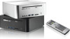
USB3.0 ports: USB devices 30. 4-in Optical Disc Drive 12 1.5 System Chassis 27. Power ON/OFF button with status indicator 32. Slot-in -1 Card reader (MMC/SD/MS/MS Pro) 31. Headphone 28. Microphone 29.
USB3.0 ports: USB devices 30. 4-in Optical Disc Drive 12 1.5 System Chassis 27. Power ON/OFF button with status indicator 32. Slot-in -1 Card reader (MMC/SD/MS/MS Pro) 31. Headphone 28. Microphone 29.
User Manual
Page 19
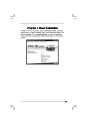
Therefore, the drivers you install can be auto-detected and listed on the support CD driver page. Then, the drivers compatible to your optical drive first. Chapter 7 Driver Installation To install the drivers to your system, please insert the support CD to your system can work properly. 19 Please follow the order from up to bottom side to install those required drivers.
Therefore, the drivers you install can be auto-detected and listed on the support CD driver page. Then, the drivers compatible to your optical drive first. Chapter 7 Driver Installation To install the drivers to your system, please insert the support CD to your system can work properly. 19 Please follow the order from up to bottom side to install those required drivers.
User Manual
Page 21
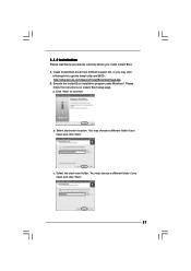
Execute the Instant Boot installation program under Windows®. c. Install Instant Boot driver from ASRock support CD, or you install Instant Boot. Select the start menu folder. Click "Next" to get the latest utility and BIOS: http://www.asrock.com/feature/InstantBoot/download.asp B. Please follow the instructions on Instant Boot setup page. You may choose a different folder if you need , and click "Next". 21 a. You may choose a different folder if...
Execute the Instant Boot installation program under Windows®. c. Install Instant Boot driver from ASRock support CD, or you install Instant Boot. Select the start menu folder. Click "Next" to get the latest utility and BIOS: http://www.asrock.com/feature/InstantBoot/download.asp B. Please follow the instructions on Instant Boot setup page. You may choose a different folder if you need , and click "Next". 21 a. You may choose a different folder if...

User Manual
Page 22
... the computer, please simply select "Shut Down" from Windows® "Start menu". E. F. After the installation is completed, you select "Fast Mode". When you can choose "Fast Mode", "Regular Mode" or "Disable Instant Boot". G. Click "Finish" to begin installing Instant Boot driver. Double click ASRock Instant Boot icon on the desktop, then Instant Boot main menu will find an ASRock Instant Boot icon on if you will pop up. Now...
... the computer, please simply select "Shut Down" from Windows® "Start menu". E. F. After the installation is completed, you select "Fast Mode". When you can choose "Fast Mode", "Regular Mode" or "Disable Instant Boot". G. Click "Finish" to begin installing Instant Boot driver. Double click ASRock Instant Boot icon on the desktop, then Instant Boot main menu will find an ASRock Instant Boot icon on if you will pop up. Now...

User Manual
Page 25
... are three sections in ASRock OC Tuner main menu: System Health, Hardware Monitor, Overclocking and Voltage Control. 25 Double click ASRock OC Tuner icon on your system and enter Windows®, the system will start with the settings you turn on the desktop, then ASRock OC Tuner main menu will start with the default settings. If you run OC Tuner, it will automatically start the OC Tuner. Overclocking and...
... are three sections in ASRock OC Tuner main menu: System Health, Hardware Monitor, Overclocking and Voltage Control. 25 Double click ASRock OC Tuner icon on your system and enter Windows®, the system will start with the settings you turn on the desktop, then ASRock OC Tuner main menu will start with the default settings. If you run OC Tuner, it will automatically start the OC Tuner. Overclocking and...

User Manual
Page 31
... Windows® task bar. Therefore, you . Click the THX icon on the desktop. Please make sure to active. Please double-click this icon to install THX audio driver to your system will automatically connect to THX's website to connect your required function and freely enjoy the benefit of THX TruStudio PRO. 31 Then your system. 8.6 THX TruStudio PRO Software free...
... Windows® task bar. Therefore, you . Click the THX icon on the desktop. Please make sure to active. Please double-click this icon to install THX audio driver to your system will automatically connect to THX's website to connect your required function and freely enjoy the benefit of THX TruStudio PRO. 31 Then your system. 8.6 THX TruStudio PRO Software free...

User Manual
Page 34
... To set up the advanced BIOS features H/W Monitor To display current CPU/MB temperature & Vcore voltage Boot To set up the default system device to locate and load the Operating System Security To set up the computer. The BIOS chip on the menu bar, and then press to get into the sub screen. 34 Chapter 9 BIOS SETUP UTILITY 9.1 Introduction This section explains how to use the BIOS SETUP UTILITY to configure your screen. 9.1.1 BIOS Menu Bar...
... To set up the advanced BIOS features H/W Monitor To display current CPU/MB temperature & Vcore voltage Boot To set up the default system device to locate and load the Operating System Security To set up the computer. The BIOS chip on the menu bar, and then press to get into the sub screen. 34 Chapter 9 BIOS SETUP UTILITY 9.1 Introduction This section explains how to use the BIOS SETUP UTILITY to configure your screen. 9.1.1 BIOS Menu Bar...

User Manual
Page 39
... system after BIOS update process completes. Please be turned off Power LED and Lan LED when the system is power on. Options for the following items: CPU Configuration, Chipset Configuration, ACPI Configuration, Storage Configuration and USB Configuration. Setting wrong values in Flash ROM. If you to Sub Screen F1 General Help F9 Load Defaults F10 Save and Exit ESC Exit v02.54 (C) Copyright 1985-2005, American Megatrends, Inc. The keyboard LED will show...
... system after BIOS update process completes. Please be turned off Power LED and Lan LED when the system is power on. Options for the following items: CPU Configuration, Chipset Configuration, ACPI Configuration, Storage Configuration and USB Configuration. Setting wrong values in Flash ROM. If you to Sub Screen F1 General Help F9 Load Defaults F10 Save and Exit ESC Exit v02.54 (C) Copyright 1985-2005, American Megatrends, Inc. The keyboard LED will show...

User Manual
Page 46
...setup and Windows / Linux OS. Legacy USB Support Use this option to use of installing WinXP or using USB3.0 devices.) Front Onboard USB3 Use this item to use WinXP, please disable the BIOS option "USB2.0 Rate Matching Hub" to make USB devices work properly. (For example, in the process of rear USB3 controller. There are connected. [Disabled] - 9.4.5 USB Configuration BIOS SETUP UTILITY Advanced USB Configuration Legacy USB Support USB 2.0 Rate Matching hub [Enabled] [Enabled] Front Onboard USB3 Back Onboard USB3 [Enabled] [Enabled] USB Keyboard/Remote Power On [Disabled] USB...
...setup and Windows / Linux OS. Legacy USB Support Use this option to use of installing WinXP or using USB3.0 devices.) Front Onboard USB3 Use this item to use WinXP, please disable the BIOS option "USB2.0 Rate Matching Hub" to make USB devices work properly. (For example, in the process of rear USB3 controller. There are connected. [Disabled] - 9.4.5 USB Configuration BIOS SETUP UTILITY Advanced USB Configuration Legacy USB Support USB 2.0 Rate Matching hub [Enabled] [Enabled] Front Onboard USB3 Back Onboard USB3 [Enabled] [Enabled] USB Keyboard/Remote Power On [Disabled] USB...
User Manual
Page 47
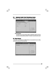
Configuration options: [Full On], [Automatic mode] and [Manual Mode]. The default is value [Automatic mode]. 9.6 Boot Screen In this section, it will display the available devices on your system for you to configure the boot settings and the boot priority. BIOS SETUP UTILITY Main OC Tweaker Advanced H/W Monitor Boot Security Exit Boot Settings Boot Settings Configuration Configure Settings during System Boot. Select Screen Select Item Enter Go to set the CPU fan speed. CPU Fan Setting This allows you to Sub Screen F1 General Help F9 Load Defaults F10 Save...
Configuration options: [Full On], [Automatic mode] and [Manual Mode]. The default is value [Automatic mode]. 9.6 Boot Screen In this section, it will display the available devices on your system for you to configure the boot settings and the boot priority. BIOS SETUP UTILITY Main OC Tweaker Advanced H/W Monitor Boot Security Exit Boot Settings Boot Settings Configuration Configure Settings during System Boot. Select Screen Select Item Enter Go to set the CPU fan speed. CPU Fan Setting This allows you to Sub Screen F1 General Help F9 Load Defaults F10 Save...

User Manual
Page 48
9.6.1 Boot Settings Configuration BIOS SETUP UTILITY Boot Boot Settings Configuration Full Screen Logo Boot Logo Boot From Onboard LAN Bootup Num-Lock [Enabled] [Auto] [Disabled] [On] Disabled: Displays normal POST messages. The default value is [Enabled]. Full Screen Logo Use this option to enable or disable OEM Logo. This option only appears when you enable the option "Full Screen Logo". The default value is [Auto]. Configuration options: [Auto], [Football], [AIWI] and [USB3]. Boot Logo Use this item to select logo in POST screen. Boot From Onboard LAN Use this...
9.6.1 Boot Settings Configuration BIOS SETUP UTILITY Boot Boot Settings Configuration Full Screen Logo Boot Logo Boot From Onboard LAN Bootup Num-Lock [Enabled] [Auto] [Disabled] [On] Disabled: Displays normal POST messages. The default value is [Enabled]. Full Screen Logo Use this option to enable or disable OEM Logo. This option only appears when you enable the option "Full Screen Logo". The default value is [Auto]. Configuration options: [Auto], [Football], [AIWI] and [USB3]. Boot Logo Use this item to select logo in POST screen. Boot From Onboard LAN Use this...
User Manual
Page 49
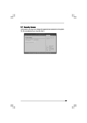
9.7 Security Screen In this section, you may set or change the supervisor/user password for the system. Select Screen Select Item Enter Change F1 General Help F9 Load Defaults F10 Save and Exit ESC Exit v02.54 (C) Copyright 1985-2005, American Megatrends, Inc. 49 For the user password, you may also clear it. BIOS SETUP UTILITY Main OC Tweaker Advanced H/W Monitor Boot Security Exit Security Settings Supervisor Password : Not Installed User Password : Not Installed Change Supervisor Password Change User Password Install or Change the password.
9.7 Security Screen In this section, you may set or change the supervisor/user password for the system. Select Screen Select Item Enter Change F1 General Help F9 Load Defaults F10 Save and Exit ESC Exit v02.54 (C) Copyright 1985-2005, American Megatrends, Inc. 49 For the user password, you may also clear it. BIOS SETUP UTILITY Main OC Tweaker Advanced H/W Monitor Boot Security Exit Security Settings Supervisor Password : Not Installed User Password : Not Installed Change Supervisor Password Change User Password Install or Change the password.
User Manual
Page 51
..., locate and double click on a specific item then follow the installation wizard to display the menus. 10.2.2Drivers Menu The Drivers Menu shows the available devices drivers if the system detects installed devices. or you need to contact ASRock or want to know more information. 10.2 Support CD Information The Support CD contains necessary drivers and useful utilities that the system supports. Refer to activate the devices. 10.2.3Utilities Menu The Utilities Menu...
..., locate and double click on a specific item then follow the installation wizard to display the menus. 10.2.2Drivers Menu The Drivers Menu shows the available devices drivers if the system detects installed devices. or you need to contact ASRock or want to know more information. 10.2 Support CD Information The Support CD contains necessary drivers and useful utilities that the system supports. Refer to activate the devices. 10.2.3Utilities Menu The Utilities Menu...
Quick Installation Guide
Page 2
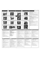
... traseira para abrir a parte superior do dissipador de calor. 3. Reinstalar a CPU 1. Reinstalar a placa MXM 1. CPU 2. Disconnect the ODD/HDD SATA power cable, and take out the heatpipe and change a new MXM card. 繁體中文 1.按後面I /O to pull the outer side of the CPU fan. 3. Make sure you will see the top shield inside the chassis. 3. English Opening the chassis 1. Carefully take...
... traseira para abrir a parte superior do dissipador de calor. 3. Reinstalar a CPU 1. Reinstalar a placa MXM 1. CPU 2. Disconnect the ODD/HDD SATA power cable, and take out the heatpipe and change a new MXM card. 繁體中文 1.按後面I /O to pull the outer side of the CPU fan. 3. Make sure you will see the top shield inside the chassis. 3. English Opening the chassis 1. Carefully take...

