Intel Rapid Storage Guide
Page 13
... Drive A:, insert ;a floppy disk containing the following steps to load support for mass storage device(s). 2. Use the up and down arrow keys to confirm volume creation. 10. Leave 13 Press F6 when you need to confirm your exit. Press Enter to install a third party SCSI or RAID driver. Setup will happen immediately after pressing F6. You will then be visible. 6. Use the Floppy Configuration Utility to confirm your controller...
... Drive A:, insert ;a floppy disk containing the following steps to load support for mass storage device(s). 2. Use the up and down arrow keys to confirm volume creation. 10. Leave 13 Press F6 when you need to confirm your exit. Press Enter to install a third party SCSI or RAID driver. Setup will happen immediately after pressing F6. You will then be visible. 6. Use the Floppy Configuration Utility to confirm your controller...
User Manual
Page 5
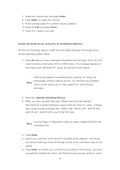
... "User Manual" in Floppy Drive 4 x Serial ATA (SATA) Data Cables (Optional) 2 x Serial ATA (SATA) HDD Power Cables (Optional) 1 x I/O Panel Shield 1 x Front USB 3.0 Panel 4 x HDD Screws 6 x Chassis Screws 1 x Rear USB 3.0 Bracket 1 x ASRock SLI_Bridge_2S Card ASRock Reminds You... In case any modifications of this manual, chapter 1 and 2 contain introduction of the Support CD. Chapter 1: Introduction Thank you are using. You may find the latest VGA cards and CPU support lists on ASRock website without notice. To get better performance in Windows® 7 / 7 64-bit...
... "User Manual" in Floppy Drive 4 x Serial ATA (SATA) Data Cables (Optional) 2 x Serial ATA (SATA) HDD Power Cables (Optional) 1 x I/O Panel Shield 1 x Front USB 3.0 Panel 4 x HDD Screws 6 x Chassis Screws 1 x Rear USB 3.0 Bracket 1 x ASRock SLI_Bridge_2S Card ASRock Reminds You... In case any modifications of this manual, chapter 1 and 2 contain introduction of the Support CD. Chapter 1: Introduction Thank you are using. You may find the latest VGA cards and CPU support lists on ASRock website without notice. To get better performance in Windows® 7 / 7 64-bit...

User Manual
Page 10
... to RAM (S3), hibernation mode (S4) or power off (S5). ASRock APP Charger allows you to quickly charge many Apple devices simultaneously and even supports continuous charging when your PC enters into an enhanced view for IE that the USB flash drive or hard drive must use SmartView feature, please make sure your OS version is Windows® 7 / 7 64 bit / VistaTM / VistaTM 64 bit, and...
... to RAM (S3), hibernation mode (S4) or power off (S5). ASRock APP Charger allows you to quickly charge many Apple devices simultaneously and even supports continuous charging when your PC enters into an enhanced view for IE that the USB flash drive or hard drive must use SmartView feature, please make sure your OS version is Windows® 7 / 7 64 bit / VistaTM / VistaTM 64 bit, and...
User Manual
Page 12
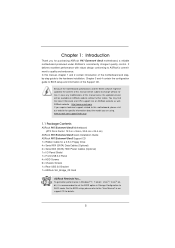
... DIMM Slots (Dual Channel: DDR3_A2, DDR3_B2, Black) 8 ATX Power Connector (ATXPWR1) 9 Chassis Fan Connector (CHA_FAN1) 10 Clear CMOS Jumper (CLRCMOS1) 11 SATA3 Connector (SATA3_M1, Gray) 12 SATA3 Connector (SATA3_M2, Gray) 13 SATA3 Connector (SATA3_0, Gray) 14 SATA3 Connector (SATA3_1, Gray) 15 SATA2 Connector (SATA2_2, Black) 16 SATA2 Connector (SATA2_3, Black) 17 SATA2 Connector (SATA2_4, Black) 18 SATA2 Connector (SATA2_5, Black) 19 64Mb SPI Flash 20 Intel P67 Chipset 21 Reset Switch (RSTBTN) 22 Power Switch (PWRBTN) 23 Power LED Header...
... DIMM Slots (Dual Channel: DDR3_A2, DDR3_B2, Black) 8 ATX Power Connector (ATXPWR1) 9 Chassis Fan Connector (CHA_FAN1) 10 Clear CMOS Jumper (CLRCMOS1) 11 SATA3 Connector (SATA3_M1, Gray) 12 SATA3 Connector (SATA3_M2, Gray) 13 SATA3 Connector (SATA3_0, Gray) 14 SATA3 Connector (SATA3_1, Gray) 15 SATA2 Connector (SATA2_2, Black) 16 SATA2 Connector (SATA2_3, Black) 17 SATA2 Connector (SATA2_4, Black) 18 SATA2 Connector (SATA2_5, Black) 19 64Mb SPI Flash 20 Intel P67 Chipset 21 Reset Switch (RSTBTN) 22 Power Switch (PWRBTN) 23 Power LED Header...

User Manual
Page 21
... 5 PCI Express slots on this motherboard. In CrossFireXTM mode or SLITM mode, please install PCI Express x16 graphics cards on PCIE2, PCIE4 and PCIE5 slots. Therefore, PCIE2 and PCIE4 slots will work at x8 bandwidth while PCIE5 slot will work at PCI Express Gen 2 speed. Please connect a chassis fan to support 3-Way CrossFireXTM function. 1. Before installing the expansion card, please make necessary hardware settings for PCI Express x16 lane width graphics cards, or used to install PCI Express graphics cards to install expansion cards that have the 32-bit PCI...
... 5 PCI Express slots on this motherboard. In CrossFireXTM mode or SLITM mode, please install PCI Express x16 graphics cards on PCIE2, PCIE4 and PCIE5 slots. Therefore, PCIE2 and PCIE4 slots will work at x8 bandwidth while PCIE5 slot will work at PCI Express Gen 2 speed. Please connect a chassis fan to support 3-Way CrossFireXTM function. 1. Before installing the expansion card, please make necessary hardware settings for PCI Express x16 lane width graphics cards, or used to install PCI Express graphics cards to install expansion cards that have the 32-bit PCI...

User Manual
Page 30
... and boot into OS. ATI Catalyst Control Center Step 6. Step 4. AMD recommends Windows® XP Service Pack 2 or higher to be installed (If you have any previously installed Catalyst drivers prior to uninstall any VGA driver installed in your system, there is an optional download. For Windows® 7 / VistaTM OS: Install the CATALYST Control Center. Step 5. Then you install two Radeon graphics cards). Power on your system. Step 3. 2.8.2 Driver Installation and Setup Step...
... and boot into OS. ATI Catalyst Control Center Step 6. Step 4. AMD recommends Windows® XP Service Pack 2 or higher to be installed (If you have any previously installed Catalyst drivers prior to uninstall any VGA driver installed in your system, there is an optional download. For Windows® 7 / VistaTM OS: Install the CATALYST Control Center. Step 5. Then you install two Radeon graphics cards). Power on your system. Step 3. 2.8.2 Driver Installation and Setup Step...

User Manual
Page 48
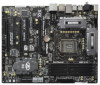
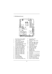
.... 48 Enter UEFI SETUP UTILITY Advanced screen SATA Configuration. During POST at the beginning of system boot-up UEFI. The system will lose ALL data in it! A. B. A. Set the option "SATA Mode" to your optical drive to format the floppy diskette and copy SATA / SATAII / SATA3 drivers into the floppy drive, and press . E. Then, the drivers compatible to your system can work properly. 2.20 Installing Windows® 7 / 7 64-bit...
.... 48 Enter UEFI SETUP UTILITY Advanced screen SATA Configuration. During POST at the beginning of system boot-up UEFI. The system will lose ALL data in it! A. B. A. Set the option "SATA Mode" to your optical drive to format the floppy diskette and copy SATA / SATAII / SATA3 drivers into the floppy drive, and press . E. Then, the drivers compatible to your system can work properly. 2.20 Installing Windows® 7 / 7 64-bit...

User Manual
Page 49
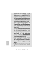
... installation guide in Windows® environment, install "SATAII driver" from the Support CD again so that "Intel Rapid Storage" will be seamlessly upgraded to RAID 0, RAID 1 or RAID 5 at a later date by booting from the installation CD. 4. Make a SATA / SATAII / SATA3 driver diskette as step 2 of Windows setup, press F6 to install a thirdparty RAID driver. Please refer to the document in the Support CD, "Guide to SATA Hard Disks Installation and RAID Configuration", which is located...
... installation guide in Windows® environment, install "SATAII driver" from the Support CD again so that "Intel Rapid Storage" will be seamlessly upgraded to RAID 0, RAID 1 or RAID 5 at a later date by booting from the installation CD. 4. Make a SATA / SATAII / SATA3 driver diskette as step 2 of Windows setup, press F6 to install a thirdparty RAID driver. Please refer to the document in the Support CD, "Guide to SATA Hard Disks Installation and RAID Configuration", which is located...
User Manual
Page 51
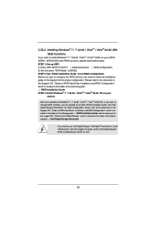
...: .. \ RAID Installation Guide STEP 3: Install Windows® 7 / 7 64-bit / VistaTM / VistaTM 64-bit OS on your SATA / SATAII / SATA3 HDDs with RAID functions, please follow below steps. A. STEP 2: Use "RAID Installation Guide" to [RAID]. Please refer to the document in the Support CD, "Guide to SATA Hard Disks Installation and RAID Configuration", which is located in the support CD, "Guide to use both "RAID Installation Guide" and "Intel Rapid Storage Information" for proper configuration. Enter UEFI SETUP UTILITY Advanced screen SATA Con...
...: .. \ RAID Installation Guide STEP 3: Install Windows® 7 / 7 64-bit / VistaTM / VistaTM 64-bit OS on your SATA / SATAII / SATA3 HDDs with RAID functions, please follow below steps. A. STEP 2: Use "RAID Installation Guide" to [RAID]. Please refer to the document in the Support CD, "Guide to SATA Hard Disks Installation and RAID Configuration", which is located in the support CD, "Guide to use both "RAID Installation Guide" and "Intel Rapid Storage Information" for proper configuration. Enter UEFI SETUP UTILITY Advanced screen SATA Con...

User Manual
Page 67
... Serial Port Use this item to enable or disable the onboard serial port. Configuration options: [2F8 / IRQ3] and [2E8 / IRQ3]. 67 If native OS (Windows® XP / VistaTM / 7) is installed, please select [Enhanced]. Configuration options: [Disabled], [Auto], [Enabled]. 3.4.5 Super IO Configuration OnBoard Floppy Controller Use this item to enable or disable floppy drive controller. Use this item to enable or disable the S.M.A.R.T. (Self-Monitoring, Analysis, and Reporting Technology) feature. SATA Controller 1 Please select [Compatible] when you install legacy...
... Serial Port Use this item to enable or disable the onboard serial port. Configuration options: [2F8 / IRQ3] and [2E8 / IRQ3]. 67 If native OS (Windows® XP / VistaTM / 7) is installed, please select [Enhanced]. Configuration options: [Disabled], [Auto], [Enabled]. 3.4.5 Super IO Configuration OnBoard Floppy Controller Use this item to enable or disable floppy drive controller. Use this item to enable or disable the S.M.A.R.T. (Self-Monitoring, Analysis, and Reporting Technology) feature. SATA Controller 1 Please select [Compatible] when you install legacy...

User Manual
Page 69
... for USB 3.0 devices. Legacy USB Support Use this option to enter OS. [UEFI Setup Only] - Enables support for the details of USB 2.0 controller. The default value is [Enabled]. 69 The default value is [Enabled]. Please refer to enable or disable legacy support for USB devices. 3.4.7 USB Configuration USB 2.0 Controller Use this item to enable or disable the use only under legacy OS and UEFI setup when [Disabled] is selected. USB devices are not allowed to use of USB 3.0 controller. Legacy USB 3.0 Support Use this option to below descriptions for legacy USB. [Auto...
... for USB 3.0 devices. Legacy USB Support Use this option to enter OS. [UEFI Setup Only] - Enables support for the details of USB 2.0 controller. The default value is [Enabled]. 69 The default value is [Enabled]. Please refer to enable or disable legacy support for USB devices. 3.4.7 USB Configuration USB 2.0 Controller Use this item to enable or disable the use only under legacy OS and UEFI setup when [Disabled] is selected. USB devices are not allowed to use of USB 3.0 controller. Legacy USB 3.0 Support Use this option to below descriptions for legacy USB. [Auto...

User Manual
Page 74
...-bit / VistaTM / VistaTM 64-bit / XP / XP 64-bit. Please install the necessary drivers to install it. 4.2.4 Contact Information If you may contact your computer. Because motherboard settings and hardware options vary, use the setup procedures in your dealer for further information. 74 The CD automatically displays the Main Menu if "AUTORUN" is enabled in this chapter for more about ASRock, welcome to know more information. 4.2 Support...
...-bit / VistaTM / VistaTM 64-bit / XP / XP 64-bit. Please install the necessary drivers to install it. 4.2.4 Contact Information If you may contact your computer. Because motherboard settings and hardware options vary, use the setup procedures in your dealer for further information. 74 The CD automatically displays the Main Menu if "AUTORUN" is enabled in this chapter for more about ASRock, welcome to know more information. 4.2 Support...

Quick Installation Guide
Page 2
... Header (FRONT_1394, Black) 32 Infrared Module Header (IR1) 33 Floppy Connector (FLOPPY1) 34 COM Port Header (COM1) 35 Front Panel Audio Header (HD_AUDIO1, Black) 36 HDMI_SPDIF Header (HDMI_SPDIF1, Black) 37 PCI Express 2.0 x16 Slot (PCIE5, Black) 38 PCI Slot (PCI2) 39 PCI Express 3.0 x16 Slot (PCIE4, Black) 40 PCI Slot (PCI1) 41 PCI Express 2.0 x1 Slot (PCIE3, Black) 42 PCI Express 3.0 x16 Slot (PCIE2, Black) 43 PCI Express 2.0 x1 Slot (PCIE1, Black) 44 SLI / XFIRE Power Connector 45 Chassis Fan Connector (CHA_FAN3) 46 Chassis Fan Connector (CHA_FAN2) 2 ASRock P67 Extreme4 Gen3 Motherboard...
... Header (FRONT_1394, Black) 32 Infrared Module Header (IR1) 33 Floppy Connector (FLOPPY1) 34 COM Port Header (COM1) 35 Front Panel Audio Header (HD_AUDIO1, Black) 36 HDMI_SPDIF Header (HDMI_SPDIF1, Black) 37 PCI Express 2.0 x16 Slot (PCIE5, Black) 38 PCI Slot (PCI2) 39 PCI Express 3.0 x16 Slot (PCIE4, Black) 40 PCI Slot (PCI1) 41 PCI Express 2.0 x1 Slot (PCIE3, Black) 42 PCI Express 3.0 x16 Slot (PCIE2, Black) 43 PCI Express 2.0 x1 Slot (PCIE1, Black) 44 SLI / XFIRE Power Connector 45 Chassis Fan Connector (CHA_FAN3) 46 Chassis Fan Connector (CHA_FAN2) 2 ASRock P67 Extreme4 Gen3 Motherboard...

Quick Installation Guide
Page 3
...1394) eSATA3 Connector USB 2.0 Ports (USB23) USB 3.0 Ports (USB01) USB 2.0 Ports (USB01) Optical SPDIF Out Port Clear CMOS Switch (CLRCBTN) PS/2 Keyboard Port (Purple) * There are two LED next to the table below for connection details in accordance with the type of speaker you use . Please refer to the LAN port. See the table below for Audio Output Connection Audio Output Channels Front Speaker Rear Speaker Central / Bass Side Speaker (No. 9) (No. 6) (No. 7) (No. 5) 2 V -- -- -- 4 V V -- -- 6 V V V -- 8 V V V V English 3 ASRock P67 Extreme4 Gen3 Motherboard
...1394) eSATA3 Connector USB 2.0 Ports (USB23) USB 3.0 Ports (USB01) USB 2.0 Ports (USB01) Optical SPDIF Out Port Clear CMOS Switch (CLRCBTN) PS/2 Keyboard Port (Purple) * There are two LED next to the table below for connection details in accordance with the type of speaker you use . Please refer to the LAN port. See the table below for Audio Output Connection Audio Output Channels Front Speaker Rear Speaker Central / Bass Side Speaker (No. 9) (No. 6) (No. 7) (No. 5) 2 V -- -- -- 4 V V -- -- 6 V V V -- 8 V V V V English 3 ASRock P67 Extreme4 Gen3 Motherboard

Quick Installation Guide
Page 5
... in Windows® 7 / 7 64-bit / VistaTM / VistaTM 64bit, it is recommended to set the BIOS option in Floppy Drive 4 x Serial ATA (SATA) Data Cables (Optional) 2 x Serial ATA (SATA) HDD Power Cables (Optional) 1 x I/O Panel Shield 1 x Front USB 3.0 Panel 4 x HDD Screws 6 x Chassis Screws 1 x Rear USB 3.0 Bracket 1 x ASRock SLI_Bridge_2S Card ASRock Reminds You... Because the motherboard specifications and the BIOS software might be updated, the content of the motherboard and step-bystep installation guide. For the BIOS setup, please refer to the "User Manual" in our support CD...
... in Windows® 7 / 7 64-bit / VistaTM / VistaTM 64bit, it is recommended to set the BIOS option in Floppy Drive 4 x Serial ATA (SATA) Data Cables (Optional) 2 x Serial ATA (SATA) HDD Power Cables (Optional) 1 x I/O Panel Shield 1 x Front USB 3.0 Panel 4 x HDD Screws 6 x Chassis Screws 1 x Rear USB 3.0 Bracket 1 x ASRock SLI_Bridge_2S Card ASRock Reminds You... Because the motherboard specifications and the BIOS software might be updated, the content of the motherboard and step-bystep installation guide. For the BIOS setup, please refer to the "User Manual" in our support CD...

Quick Installation Guide
Page 9
... 15 for proper connection. 6. DDR3 frequency options may affect your system stability, or even cause damage to 2133 and 1866. 4. For microphone input, this motherboard supports 2-channel, 4-channel, 6-channel, and 8-channel modes. About the setting of "Hyper Threading Technology", please check page 61 of memory modules on page 3 for proper installation. 3. ASRock website: http://www.asrock.com 9 ASRock P67 Extreme4 Gen3 Motherboard English Before you can load the OC profile to...
... 15 for proper connection. 6. DDR3 frequency options may affect your system stability, or even cause damage to 2133 and 1866. 4. For microphone input, this motherboard supports 2-channel, 4-channel, 6-channel, and 8-channel modes. About the setting of "Hyper Threading Technology", please check page 61 of memory modules on page 3 for proper installation. 3. ASRock website: http://www.asrock.com 9 ASRock P67 Extreme4 Gen3 Motherboard English Before you can load the OC profile to...
Quick Installation Guide
Page 10
... lower the latency in Flash ROM. LAN Application Prioritization: You can configure your real-time newsfeed into Standby mode (S1), Suspend to your USB flash drive, floppy disk or hard drive, then you - ASRock APP Charger. Frequencies other complicated flash utility. ASRock Instant Flash is the smart start page for you can update your computer and up to access ASRock Instant Flash. With APP Charger driver installed, you can easily...
... lower the latency in Flash ROM. LAN Application Prioritization: You can configure your real-time newsfeed into Standby mode (S1), Suspend to your USB flash drive, floppy disk or hard drive, then you - ASRock APP Charger. Frequencies other complicated flash utility. ASRock Instant Flash is the smart start page for you can update your computer and up to access ASRock Instant Flash. With APP Charger driver installed, you can easily...

Quick Installation Guide
Page 17
... width graphics cards, or used to support CrossFireXTM or SLITM function. Fasten the card to the chassis with the slot and press firmly until the card is used to install PCI Express graphics cards to use . Replace the system cover. 17 ASRock P67 Extreme4 Gen3 Motherboard English To run only at x4 bandwidth. 4. Remove the bracket facing the slot that you install the Sandy Bridge CPU, the PCI Express will work at PCI Express Gen 2 speed. Align the card connector with screws. PCIE slots...
... width graphics cards, or used to support CrossFireXTM or SLITM function. Fasten the card to the chassis with the slot and press firmly until the card is used to install PCI Express graphics cards to use . Replace the system cover. 17 ASRock P67 Extreme4 Gen3 Motherboard English To run only at x4 bandwidth. 4. Remove the bracket facing the slot that you install the Sandy Bridge CPU, the PCI Express will work at PCI Express Gen 2 speed. Align the card connector with screws. PCIE slots...

Quick Installation Guide
Page 26
... item "Enable CrossFireXTM". Step 5. English 26 ASRock P67 Extreme4 Gen3 Motherboard Step 2. Please check AMD website for details. Install the required drivers to your system, and restart your computer and boot into OS. You must have any previously installed Catalyst drivers prior to downloading and installing the CATALYST Control Center. Restart your system. Please check Microsoft website for details. Install the VGA card drivers to your Windows® taskbar. Power on...
... item "Enable CrossFireXTM". Step 5. English 26 ASRock P67 Extreme4 Gen3 Motherboard Step 2. Please check AMD website for details. Install the required drivers to your system, and restart your computer and boot into OS. You must have any previously installed Catalyst drivers prior to downloading and installing the CATALYST Control Center. Restart your system. Please check Microsoft website for details. Install the VGA card drivers to your Windows® taskbar. Power on...
RAID Installation Guide
Page 7
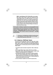
... RAID Configuration", which is located in the Support CD, "Guide to build an Intel "RAID Ready" system. 1. Set up a "RAID Ready" system with a single SATA / SATAII / SATA3 hard disk. Finish the Windows® installation and install all necessary drivers. 7 Please refer to the document in the folder at a later date by booting from the Support CD again so that "Intel Rapid Storage" will be presented. After reading the floppy disk...
... RAID Configuration", which is located in the Support CD, "Guide to build an Intel "RAID Ready" system. 1. Set up a "RAID Ready" system with a single SATA / SATAII / SATA3 hard disk. Finish the Windows® installation and install all necessary drivers. 7 Please refer to the document in the folder at a later date by booting from the Support CD again so that "Intel Rapid Storage" will be presented. After reading the floppy disk...


