
User Manual
Page 3
... 2.8 Package Contents ...Specifications ...Motherboard Layout (P4i45GL) ...Motherboard Layout (P4i45GV) ...ASRock I/OTM (P4i45GL / P4i45GV) ...Screw Holes ...Pre-installation Precautions ...CPU Installation ...Installation of Heatsink and CPU fan ...Installation of Memory Modules (DIMM) ...Expansion Slots ...Jumpers Setup ...Connectors ...4 5 8 9 10 11 11 12 12 13 13 14 15 17 17 17 18 20 21 21 21 21 21 21 21 22 26 27 28 29 2 Installation ...11 3 BIOS Setup ...17 3.1 BIOS Setup Utility ...3.1.1 BIOS Menu Bar ...3.1.2 Legend Bar ...3.2 Main Menu ...3.3 Advanced, Security, Power, Boot, and Exit...
... 2.8 Package Contents ...Specifications ...Motherboard Layout (P4i45GL) ...Motherboard Layout (P4i45GV) ...ASRock I/OTM (P4i45GL / P4i45GV) ...Screw Holes ...Pre-installation Precautions ...CPU Installation ...Installation of Heatsink and CPU fan ...Installation of Memory Modules (DIMM) ...Expansion Slots ...Jumpers Setup ...Connectors ...4 5 8 9 10 11 11 12 12 13 13 14 15 17 17 17 18 20 21 21 21 21 21 21 21 22 26 27 28 29 2 Installation ...11 3 BIOS Setup ...17 3.1 BIOS Setup Utility ...3.1.1 BIOS Menu Bar ...3.1.2 Legend Bar ...3.2 Main Menu ...3.3 Advanced, Security, Power, Boot, and Exit...

User Manual
Page 4
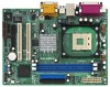
... 1 cable for IDE devices (1 x ATA 66 / 100) 1 cable for purchasing ASRock P4i45GL / P4i45GV motherboard, a reliable motherboard produced under ASRock's consistently stringent quality control. For advanced users' reference, the Appendix appearing on ASRock website without notice. In case any modifications of the motherboard and step-bystep installation guide for new DIY system builders. You may find the latest memory and CPU support lists on ASRock website as well. Because the motherboard specifications and the BIOS software...
... 1 cable for IDE devices (1 x ATA 66 / 100) 1 cable for purchasing ASRock P4i45GL / P4i45GV motherboard, a reliable motherboard produced under ASRock's consistently stringent quality control. For advanced users' reference, the Appendix appearing on ASRock website without notice. In case any modifications of the motherboard and step-bystep installation guide for new DIY system builders. You may find the latest memory and CPU support lists on ASRock website as well. Because the motherboard specifications and the BIOS software...

User Manual
Page 5
... Chassis fan tachometer PCI slots: 2 slots with PCI Specification 2.2 AMR slot: 1 slot, supports ASRock MR card (Optional) USB 2.0: 4 default USB 2.0 ports and 1 extra set of header for Intel® Pentium® 4 / Celeron® processor North Bridge (P4i45GL): Intel® 845GL chipsets, standard FSB 400MHz (see CAUTION 1), Max. 533 MHz (at overclocking mode, see CAUTION 5); P4i45GV: 2 DDR DIMM slots, DDR DIMM1 and DDR DIMM2 supports PC2100 (DDR266) / PC2700 (DDR333), Max. 2GB (see CAUTION 3); CPU overheat shutdown to 4 IDE devices Floppy Port: Supports 2 floppy disk drives Audio...
... Chassis fan tachometer PCI slots: 2 slots with PCI Specification 2.2 AMR slot: 1 slot, supports ASRock MR card (Optional) USB 2.0: 4 default USB 2.0 ports and 1 extra set of header for Intel® Pentium® 4 / Celeron® processor North Bridge (P4i45GL): Intel® 845GL chipsets, standard FSB 400MHz (see CAUTION 1), Max. 533 MHz (at overclocking mode, see CAUTION 5); P4i45GV: 2 DDR DIMM slots, DDR DIMM1 and DDR DIMM2 supports PC2100 (DDR266) / PC2700 (DDR333), Max. 2GB (see CAUTION 3); CPU overheat shutdown to 4 IDE devices Floppy Port: Supports 2 floppy disk drives Audio...

User Manual
Page 6
... motherboard. 6 BIOS: OS: AMI legal BIOS; Please check if the CPU fan on page 7 for the details. 2. Although P4i45GL / P4i45GV offers stepless control,it will support PC2100(DDR266) and PC2800(DDR350). 3. Frequencies other clocks, such as PCI clock and Memory clock will automatically shutdown. Supports "Plug and Play"; SMBIOS 2.3.1 support; Please refer to perform over clocking, other than the recommended CPU bus frequencies may not work properly under Microsoft® Windows® XP. CPU frequency...
... motherboard. 6 BIOS: OS: AMI legal BIOS; Please check if the CPU fan on page 7 for the details. 2. Although P4i45GL / P4i45GV offers stepless control,it will support PC2100(DDR266) and PC2800(DDR350). 3. Frequencies other clocks, such as PCI clock and Memory clock will automatically shutdown. Supports "Plug and Play"; SMBIOS 2.3.1 support; Please refer to perform over clocking, other than the recommended CPU bus frequencies may not work properly under Microsoft® Windows® XP. CPU frequency...
User Manual
Page 8
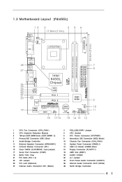
...CPU_FAN1) CPU Heatsink Retention Module 184-pin DDR DIMM Slots (DDR DIMM1- 2) Primary IDE Connector (IDE1, Blue) South Bridge Controller External Speaker Connector (SPEAKER1) Infrared Module Connector (IR1) Clear CMOS (CLRCMOS0, 2-pin jumper) Serial Port Connector (COM1) BIOS FWH Chip PCI Slots (PCI 1- 2) JR1 Jumper PCI LAN (Optional) Internal Audio Connector: CD1 (Black) 2 4 6 8 10 12 14 16 18 20 22 24 26 28 PS2_USB_PWR1 Jumper CPU Socket ATX Power Connector (ATXPWR1) Secondary IDE Connector (IDE2, Black) Chassis Fan Connector (CHA_FAN1) System Panel Connector (PANEL1) USB 2.0 Header (USB45...
...CPU_FAN1) CPU Heatsink Retention Module 184-pin DDR DIMM Slots (DDR DIMM1- 2) Primary IDE Connector (IDE1, Blue) South Bridge Controller External Speaker Connector (SPEAKER1) Infrared Module Connector (IR1) Clear CMOS (CLRCMOS0, 2-pin jumper) Serial Port Connector (COM1) BIOS FWH Chip PCI Slots (PCI 1- 2) JR1 Jumper PCI LAN (Optional) Internal Audio Connector: CD1 (Black) 2 4 6 8 10 12 14 16 18 20 22 24 26 28 PS2_USB_PWR1 Jumper CPU Socket ATX Power Connector (ATXPWR1) Secondary IDE Connector (IDE2, Black) Chassis Fan Connector (CHA_FAN1) System Panel Connector (PANEL1) USB 2.0 Header (USB45...
User Manual
Page 9
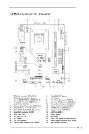
...CPU_FAN1) CPU Heatsink Retention Module 184-pin DDR DIMM Slots (DDR DIMM1- 2) Primary IDE Connector (IDE1, Blue) South Bridge Controller External Speaker Connector (SPEAKER1) Infrared Module Connector (IR1) Clear CMOS (CLRCMOS0, 2-pin jumper) Serial Port Connector (COM1) BIOS FWH Chip PCI Slots (PCI 1- 2) JR1 Jumper PCI LAN (Optional) Internal Audio Connector: CD1 (Black) 2 4 6 8 10 12 14 16 18 20 22 24 26 28 PS2_USB_PWR1 Jumper CPU Socket ATX Power Connector (ATXPWR1) Secondary IDE Connector (IDE2, Black) Chassis Fan Connector (CHA_FAN1) System Panel Connector (PANEL1) USB 2.0 Header (USB45...
...CPU_FAN1) CPU Heatsink Retention Module 184-pin DDR DIMM Slots (DDR DIMM1- 2) Primary IDE Connector (IDE1, Blue) South Bridge Controller External Speaker Connector (SPEAKER1) Infrared Module Connector (IR1) Clear CMOS (CLRCMOS0, 2-pin jumper) Serial Port Connector (COM1) BIOS FWH Chip PCI Slots (PCI 1- 2) JR1 Jumper PCI LAN (Optional) Internal Audio Connector: CD1 (Black) 2 4 6 8 10 12 14 16 18 20 22 24 26 28 PS2_USB_PWR1 Jumper CPU Socket ATX Power Connector (ATXPWR1) Secondary IDE Connector (IDE2, Black) Chassis Fan Connector (CHA_FAN1) System Panel Connector (PANEL1) USB 2.0 Header (USB45...
User Manual
Page 11
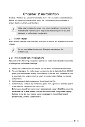
... use a grounded wrist strap or touch a safety grounded object before you install the motherboard, study the configuration of the following precautions before installing or removing the motherboard. Chapter 2 Installation P4i45GL / P4i45GV is detached from the wall socket before touching any motherboard settings. 1. To avoid damaging the motherboard components due to the motherboard, peripherals, and/or components. 11 Make sure to ensure that the power is switched...
... use a grounded wrist strap or touch a safety grounded object before you install the motherboard, study the configuration of the following precautions before installing or removing the motherboard. Chapter 2 Installation P4i45GL / P4i45GV is detached from the wall socket before touching any motherboard settings. 1. To avoid damaging the motherboard components due to the motherboard, peripherals, and/or components. 11 Make sure to ensure that the power is switched...

User Manual
Page 14
... clear and reset the system parameters to default setup, please turn off the computer and unplug the power cord, then use a jumper cap to short the pins on these 2 pins. Jumper PS2_USB_PWR1 (see p.8/p.9 item 2) Setting 1_2 +5V 2_3 +5VSB Description Short pin2, pin3 to clear the data in CMOS. The data in back panel and front panel at the same time, 1. If both front panel and rear panel audio connectors can work. 2. Clear CMOS CLRCMOS0...
... clear and reset the system parameters to default setup, please turn off the computer and unplug the power cord, then use a jumper cap to short the pins on these 2 pins. Jumper PS2_USB_PWR1 (see p.8/p.9 item 2) Setting 1_2 +5V 2_3 +5VSB Description Short pin2, pin3 to clear the data in CMOS. The data in back panel and front panel at the same time, 1. If both front panel and rear panel audio connectors can work. 2. Clear CMOS CLRCMOS0...
User Manual
Page 17
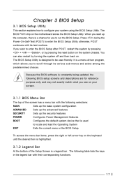
... features POWER Configures Power Management features BOOT Configures the default system device that is used to run the BIOS Setup. The BIOS FWH chip on . You can also restart by pressing the reset button on your system using the BIOS Setup Utility. Because the BIOS software is constantly being updated, the following BIOS setup screens and descriptions are for you to locate and load the Operating System EXIT Exits the current menu or the BIOS Setup To access the menu bar...
... features POWER Configures Power Management features BOOT Configures the default system device that is used to run the BIOS Setup. The BIOS FWH chip on . You can also restart by pressing the reset button on your system using the BIOS Setup Utility. Because the BIOS software is constantly being updated, the following BIOS setup screens and descriptions are for you to locate and load the Operating System EXIT Exits the current menu or the BIOS Setup To access the menu bar...

User Manual
Page 18
... F1:Help Esc:Exit :Select Item :Select Menu +/-:Change Values Enter:Select Sub-Menu F9:Setup Defaults F10:Save & Exit System Date [Month/Day/Year] Set the system date that you specify. Floppy Drives Use this to set the type of floppy drives installed. AMIBIOS SETUP UTILITY - VERSION 3.31a Boot Power Exit Main Advanced Security [ System Date System Time Floppy Drives IDE Devices BIOS Version Processor Type Processor Speed Cache Size Microcode Update Total Memory DDR1 DDR2 Setup Help ] Jun 27 2003 Fri 20:07...
... F1:Help Esc:Exit :Select Item :Select Menu +/-:Change Values Enter:Select Sub-Menu F9:Setup Defaults F10:Save & Exit System Date [Month/Day/Year] Set the system date that you specify. Floppy Drives Use this to set the type of floppy drives installed. AMIBIOS SETUP UTILITY - VERSION 3.31a Boot Power Exit Main Advanced Security [ System Date System Time Floppy Drives IDE Devices BIOS Version Processor Type Processor Speed Cache Size Microcode Update Total Memory DDR1 DDR2 Setup Help ] Jun 27 2003 Fri 20:07...
User Manual
Page 19
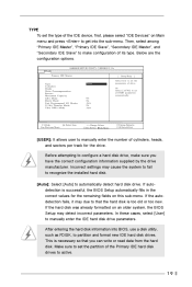
... configuration of drive, Or Select [AUTO] to set all HDD parameters automatically. After entering the hard disk information into the sub-menu. Below are the configuration options. On On Auto On Auto Type Cylinders Heads Write Precompensation Sectors Maximum Capacity LBA Mode Block Mode Fast Programmed I/O Modes 32 Bit Transfer Mode Ultra DMA Mode F1:Help Esc:Previous Menu :Select Item +/-:Change Values Enter:Select Sub-Menu F9:Setup Defaults F10:Save & Exit [USER]: It allows user to manually enter...
... configuration of drive, Or Select [AUTO] to set all HDD parameters automatically. After entering the hard disk information into the sub-menu. Below are the configuration options. On On Auto On Auto Type Cylinders Heads Write Precompensation Sectors Maximum Capacity LBA Mode Block Mode Fast Programmed I/O Modes 32 Bit Transfer Mode Ultra DMA Mode F1:Help Esc:Previous Menu :Select Item +/-:Change Values Enter:Select Sub-Menu F9:Setup Defaults F10:Save & Exit [USER]: It allows user to manually enter...

User Manual
Page 20
... values. Fast Programmed I/O Modes This allows user to set the PIO mode to enhance hard disk performance by the BIOS based on the drive information you entered. Ultra DMA Mode Ultra DMA capability allows improved transfer speeds and data integrity for IDE ARMD (ATAPI Removable Media Device), such as calculated by optimizing the hard disk timing. 32 Bit Transfer Mode It allows user to enable 32-bit access to determine the correct...
... values. Fast Programmed I/O Modes This allows user to set the PIO mode to enhance hard disk performance by the BIOS based on the drive information you entered. Ultra DMA Mode Ultra DMA capability allows improved transfer speeds and data integrity for IDE ARMD (ATAPI Removable Media Device), such as calculated by optimizing the hard disk timing. 32 Bit Transfer Mode It allows user to enable 32-bit access to determine the correct...

User Manual
Page 21
... the motherboard supports. Chapter 4 Software Support 4.1 Install Operating System This motherboard supports various Microsoft® Windows® operating systems: 98 SE / ME / 2000 / XP. Because motherboard settings and hardware options vary, use the setup procedures in this demo program, you need to contact ASRock or want to install your own PC system step by step. If the Main Menu did not appear automatically, locate and double click on a specific...
... the motherboard supports. Chapter 4 Software Support 4.1 Install Operating System This motherboard supports various Microsoft® Windows® operating systems: 98 SE / ME / 2000 / XP. Because motherboard settings and hardware options vary, use the setup procedures in this demo program, you need to contact ASRock or want to install your own PC system step by step. If the Main Menu did not appear automatically, locate and double click on a specific...

User Manual
Page 22
... BIOS Setup This section will be [Disabled] for better system stability. VERSION 3.31a Boot Power Exit [ Spread Spectrum CPU Host Frequency Actual Frequency CPU Ratio Selection SDRAM Frequency Hyper Threading Technology Chipset Configuration Resource Configuration Peripheral Configuration System Hardware Monitor Setup Help ] Disabled Auto 133MHz Locked Auto Auto to [Auto] if using Microsoft® Windows® XP, or Linux kernel version 2.4.18 or higher. CPU Ratio Selection: CPU Ratio is selected, the motherboard will equal the core speed of the installed processor. SDRAM Frequency...
... BIOS Setup This section will be [Disabled] for better system stability. VERSION 3.31a Boot Power Exit [ Spread Spectrum CPU Host Frequency Actual Frequency CPU Ratio Selection SDRAM Frequency Hyper Threading Technology Chipset Configuration Resource Configuration Peripheral Configuration System Hardware Monitor Setup Help ] Disabled Auto 133MHz Locked Auto Auto to [Auto] if using Microsoft® Windows® XP, or Linux kernel version 2.4.18 or higher. CPU Ratio Selection: CPU Ratio is selected, the motherboard will equal the core speed of the installed processor. SDRAM Frequency...
User Manual
Page 23
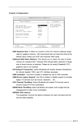
... size of USB controller. USB Device Legacy Support: Use this to keep it from overheated. VERSION 3.31a Advanced Chipset Configuration [ Setup Help ] AGP Aperture Size Onboard VGA Share Memory ICH Delayed Transaction USB Controller USB Device Legacy Support CPU Thermal Throttling DRAM Write Throttling SDRAM CAS Latency 64MB 1MB Disabled Enabled Disabled Enabled Enabled Auto to a section of share memory for graphics memory. We recommend that you to keep CPU from overheated. Please do not select [Disabled] if PCI graphics card is selected. Onboard VGA will enable...
... size of USB controller. USB Device Legacy Support: Use this to keep it from overheated. VERSION 3.31a Advanced Chipset Configuration [ Setup Help ] AGP Aperture Size Onboard VGA Share Memory ICH Delayed Transaction USB Controller USB Device Legacy Support CPU Thermal Throttling DRAM Write Throttling SDRAM CAS Latency 64MB 1MB Disabled Enabled Disabled Enabled Enabled Auto to a section of share memory for graphics memory. We recommend that you to keep CPU from overheated. Please do not select [Disabled] if PCI graphics card is selected. Onboard VGA will enable...

User Manual
Page 24
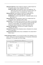
... OnBoard Serial Port OnBoard Infrared Port OnBoard Parallel Port Parallel Port Mode EPP Version Parallel Port IRQ Parallel Port DMA Channel OnBoard Midi Port Midi IRQ Select OnBoard Game Port OnBoard IDE OnBoard LAN OnBoard AC' 97 Audio OnBoard MC' 97 Modem Auto Auto Disabled Auto ECP + EPP 1.9 Auto Auto Disabled 5 200H Both Enabled Auto Auto F1:Help Esc:Previous Menu :Select Item +/-:Change Values Enter:Select Sub-Menu F9:Setup Defaults F10:Save & Exit OnBoard FDC: Use this to select [PCI / Int-VGA], or [Internal VGA] as the primary graphics adapter. Configuration options: [Auto...
... OnBoard Serial Port OnBoard Infrared Port OnBoard Parallel Port Parallel Port Mode EPP Version Parallel Port IRQ Parallel Port DMA Channel OnBoard Midi Port Midi IRQ Select OnBoard Game Port OnBoard IDE OnBoard LAN OnBoard AC' 97 Audio OnBoard MC' 97 Modem Auto Auto Disabled Auto ECP + EPP 1.9 Auto Auto Disabled 5 200H Both Enabled Auto Auto F1:Help Esc:Previous Menu :Select Item +/-:Change Values Enter:Select Sub-Menu F9:Setup Defaults F10:Save & Exit OnBoard FDC: Use this to select [PCI / Int-VGA], or [Internal VGA] as the primary graphics adapter. Configuration options: [Auto...
User Manual
Page 25
... port. The default value is set to monitor the parameters for CPU temperature, Motherboard temperature, CPU fan speed, and critical voltage. OnBoard IDE: You may enable both . OnBoard AC'97 Audio: Select [Disabled], [Auto] or [Enabled] for Midi Port or disable Midi Port. OnBoard LAN (Optional): This allows you may enable either the primary IDE channel or the secondary IDE channel. OnBoard Game Port: Select address for the onboard MC'97 Modem feature. Set to enable or disable the "OnBoard LAN" feature. OnBoard MC'97 Modem: Select [Auto] or [Disabled] for Game Port...
... port. The default value is set to monitor the parameters for CPU temperature, Motherboard temperature, CPU fan speed, and critical voltage. OnBoard IDE: You may enable both . OnBoard AC'97 Audio: Select [Disabled], [Auto] or [Enabled] for Midi Port or disable Midi Port. OnBoard LAN (Optional): This allows you may enable either the primary IDE channel or the secondary IDE channel. OnBoard Game Port: Select address for the onboard MC'97 Modem feature. Set to enable or disable the "OnBoard LAN" feature. OnBoard MC'97 Modem: Select [Auto] or [Disabled] for Game Port...

User Manual
Page 26
Security Setup Menu Main Advanced Security AMIBIOS SETUP UTILITY - VERSION 3.31a Boot Power Exit Supervisor Password User Password Set Supervisor Password Set User Password Password Check Clear Clear [ Enter ] [ Enter ] Setup [ Setup Help ] to set Supervisor Password. Set Supervisor Password: Press to 6 alphanumeric characters combination. Password Check: Select the check point for "Password Check". If [Setup] option is selected, the "Password Check" is performed before BIOS setup. Valid password can be a 1 to set the supervisor password. Valid password can be a 1 ...
Security Setup Menu Main Advanced Security AMIBIOS SETUP UTILITY - VERSION 3.31a Boot Power Exit Supervisor Password User Password Set Supervisor Password Set User Password Password Check Clear Clear [ Enter ] [ Enter ] Setup [ Setup Help ] to set Supervisor Password. Set Supervisor Password: Press to 6 alphanumeric characters combination. Password Check: Select the check point for "Password Check". If [Setup] option is selected, the "Password Check" is performed before BIOS setup. Valid password can be a 1 to set the supervisor password. Valid password can be a 1 ...

User Manual
Page 27
... Menu +/-:Change Values Enter:Select Sub-Menu F9:Setup Defaults F10:Save & Exit Suspend to repost video on STR resume. It is selected, the AC/power remains off mode. Power Setup Menu Main Advanced Security AMIBIOS SETUP UTILITY - PCI Devices Power On: Use this feature if the system supports it. If [Power On] is selected, you must fill the RTC Alarm Date / Hour / Minute / Second sub-fields with the actual wake up...
... Menu +/-:Change Values Enter:Select Sub-Menu F9:Setup Defaults F10:Save & Exit Suspend to repost video on STR resume. It is selected, the AC/power remains off mode. Power Setup Menu Main Advanced Security AMIBIOS SETUP UTILITY - PCI Devices Power On: Use this feature if the system supports it. If [Power On] is selected, you must fill the RTC Alarm Date / Hour / Minute / Second sub-fields with the actual wake up...

User Manual
Page 28
... Disabled to enable or disable "boot from network" feature. Boot From Network: Use this mode will automatically activate the Numeric Lock function after boot-up to set the boot device priority. 28 Boot Device Priority: This allows you to OS/2 operating system. F1:Help Esc:Exit :Select Item :Select Menu +/-:Change Values Enter:Select Sub-Menu F9:Setup Defaults F10:Save & Exit Quick Boot Mode: Enable this to enable or disable the quick boot mode. Boot Setup Menu Main Advanced Security AMIBIOS SETUP UTILITY - Boot...
... Disabled to enable or disable "boot from network" feature. Boot From Network: Use this mode will automatically activate the Numeric Lock function after boot-up to set the boot device priority. 28 Boot Device Priority: This allows you to OS/2 operating system. F1:Help Esc:Exit :Select Item :Select Menu +/-:Change Values Enter:Select Sub-Menu F9:Setup Defaults F10:Save & Exit Quick Boot Mode: Enable this to enable or disable the quick boot mode. Boot Setup Menu Main Advanced Security AMIBIOS SETUP UTILITY - Boot...


