User Manual
Page 3
... Menu 31 4. Exit Menu 33 3 Contents 1 Introduction 4 1.1 Package Contents 4 1.2 Specifications 5 1.3 Motherboard Layout 7 1.4 ASRock I/O PlusTM 8 2 Installation 9 2.1 Screw Holes 9 2.2 Pre-installation Precautions 9 2.3 CPU Installation 10 2.4 Installation of CPU Fan...22 3.3 Advanced, Security, Power, Boot, and Exit Menus ..... 24 4 Software Support 25 4.1 Install Operating System 25 4.2 Support CD Information 25 4.2.1 Running Support CD 25 4.2.2 Drivers Menu 25 4.2.3 Utilities Menu 25 4.2.4 ASRock "PC-DIY Live Demo" Program 25 4.2.5 Contact Information 25 Appendix 26 1. Boot...
... Menu 31 4. Exit Menu 33 3 Contents 1 Introduction 4 1.1 Package Contents 4 1.2 Specifications 5 1.3 Motherboard Layout 7 1.4 ASRock I/O PlusTM 8 2 Installation 9 2.1 Screw Holes 9 2.2 Pre-installation Precautions 9 2.3 CPU Installation 10 2.4 Installation of CPU Fan...22 3.3 Advanced, Security, Power, Boot, and Exit Menus ..... 24 4 Software Support 25 4.1 Install Operating System 25 4.2 Support CD Information 25 4.2.1 Running Support CD 25 4.2.2 Drivers Menu 25 4.2.3 Utilities Menu 25 4.2.4 ASRock "PC-DIY Live Demo" Program 25 4.2.5 Contact Information 25 Appendix 26 1. Boot...
User Manual
Page 4
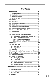
... motherboard specifications and the BIOS software might be available on ASRock website without notice. Chapter 3 and 4 contain basic BIOS setup and support CD information. ASRock website http://www.asrock.com 1.1 Package Contents ASRock P4VT8+ Motherboard (ATX Form Factor: 12.0-in x 7.5-in, 30.5 cm x 19.1 cm) ASRock P4VT8+ Quick Installation Guide ASRock P4VT8+ Support CD One 80-conductor Ultra ATA 66/100/133 IDE...
... motherboard specifications and the BIOS software might be available on ASRock website without notice. Chapter 3 and 4 contain basic BIOS setup and support CD information. ASRock website http://www.asrock.com 1.1 Package Contents ASRock P4VT8+ Motherboard (ATX Form Factor: 12.0-in x 7.5-in, 30.5 cm x 19.1 cm) ASRock P4VT8+ Quick Installation Guide ASRock P4VT8+ Support CD One 80-conductor Ultra ATA 66/100/133 IDE...
User Manual
Page 14
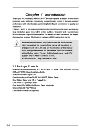
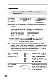
... transfer rate. Besides, to optimize compatibility and performance, please connect your hard disk drive to the primary IDE connector (IDE1, blue) and CD-ROM to the instruction of your IDE device vendor for internal storage devices. Serial ATA (SATA) Data Cable Either end of the connector. ...FDD Connector (33-pin FLOPPY1) (see p.7 item 11) SATA2 SATA1 These two Serial ATA (SATA) connectors support SATA data cables for the details. Primary IDE Connector (Blue) Secondary IDE Connector (Black) (39-pin IDE1, see p.7 item 8) (39-pin IDE2, see...
... transfer rate. Besides, to optimize compatibility and performance, please connect your hard disk drive to the primary IDE connector (IDE1, blue) and CD-ROM to the instruction of your IDE device vendor for internal storage devices. Serial ATA (SATA) Data Cable Either end of the connector. ...FDD Connector (33-pin FLOPPY1) (see p.7 item 11) SATA2 SATA1 These two Serial ATA (SATA) connectors support SATA data cables for the details. Primary IDE Connector (Blue) Secondary IDE Connector (Black) (39-pin IDE1, see p.7 item 8) (39-pin IDE2, see...
User Manual
Page 15
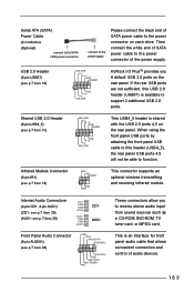
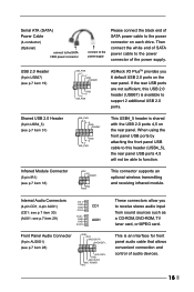
...Audio Connectors (4-pin CD1, 4-pin AUX1) (CD1: see p.7 item 30) (AUX1: see p.7 item 19) USB_PWR P-7 P+7 GND DUMMY 1 GND P+6 P-6 USB_PWR ASRock I/O PlusTM provides you to the power connector on the rear panel. O U T- O U T- Then connect the white end of SATA power cable to the power ...(9-pin AUDIO1) (see p.7 item 18) IRTX +5V DUMMY 1 GND IRRX This connector supports an optional wireless transmitting and receiving infrared module. USB 2.0 Header (9-pin USB67) (see p.7 item 29) CD-L GND GND CD-R AUX-L GND GND AUX-R CD1 AUX1 These connectors allow you 6 default USB 2.0 ports...
...Audio Connectors (4-pin CD1, 4-pin AUX1) (CD1: see p.7 item 30) (AUX1: see p.7 item 19) USB_PWR P-7 P+7 GND DUMMY 1 GND P+6 P-6 USB_PWR ASRock I/O PlusTM provides you to the power connector on the rear panel. O U T- O U T- Then connect the white end of SATA power cable to the power ...(9-pin AUDIO1) (see p.7 item 18) IRTX +5V DUMMY 1 GND IRRX This connector supports an optional wireless transmitting and receiving infrared module. USB 2.0 Header (9-pin USB67) (see p.7 item 29) CD-L GND GND CD-R AUX-L GND GND AUX-R CD1 AUX1 These connectors allow you 6 default USB 2.0 ports...
User Manual
Page 17
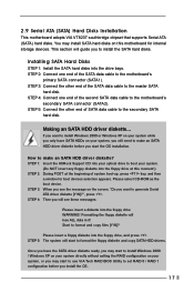
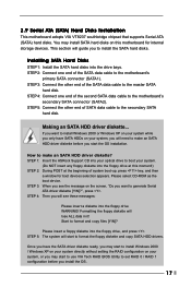
...the floppy diskette and copy SATA HDD drivers. This section will lose ALL data in it! Making an SATA HDD driver diskette... STEP 1: Insert the ASRock Support CD into your optical drive to boot your system. (Do NOT insert any floppy diskette into the floppy drive WARNING! STEP 3: When you start the OS... SATA driver diskette ready, you may install SATA hard disks on your system, or you to the motherboard's secondary SATA connector (SATA2). Please select CD-ROM as the boot device. If you want to the master SATA hard disk. You may start to make an SATA HDD driver diskette? Installing...
...the floppy diskette and copy SATA HDD drivers. This section will lose ALL data in it! Making an SATA HDD driver diskette... STEP 1: Insert the ASRock Support CD into your optical drive to boot your system. (Do NOT insert any floppy diskette into the floppy drive WARNING! STEP 3: When you start the OS... SATA driver diskette ready, you may install SATA hard disks on your system, or you to the motherboard's secondary SATA connector (SATA2). Please select CD-ROM as the boot device. If you want to the master SATA hard disk. You may start to make an SATA HDD driver diskette? Installing...
User Manual
Page 18
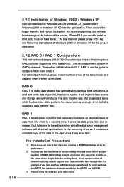
... this moment, please press key and follow the instructions of Windows 2000 or Windows XP, please insert Windows 2000 or Windows XP CD into the optical drive. It provides data protection and increases fault tolerance to the entire system since it will double the data transfer... 2000 or Windows XP for the proper installation. 2.9.2 RAID 0 / RAID 1 Configurations This motherboard adopts VIA VT8237 southbridge chipset that integrates RAID controller supporting RAID 0 and RAID 1 with two independent Serial ATA (SATA) channels. You may use two new drives or use an existing drive and a ...
... this moment, please press key and follow the instructions of Windows 2000 or Windows XP, please insert Windows 2000 or Windows XP CD into the optical drive. It provides data protection and increases fault tolerance to the entire system since it will double the data transfer... 2000 or Windows XP for the proper installation. 2.9.2 RAID 0 / RAID 1 Configurations This motherboard adopts VIA VT8237 southbridge chipset that integrates RAID controller supporting RAID 0 and RAID 1 with two independent Serial ATA (SATA) channels. You may use two new drives or use an existing drive and a ...
User Manual
Page 20
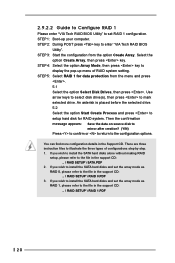
... option Select Disk Drives, then press . Select the option Create Array, then press key. There are three instruction files to the file in the support CD: .. \ RAID SETUP \ RAID 1.PDF 20 If you wish to install the SATA hard disks alone without making RAID setup, please refer to ...confirm or to return to set RAID 1 configuration. You can find more configuration details in the support CD: .. \ RAID SETUP \ RAID 0.PDF 3. STEP 4: Select the option Array Mode, then press key to the file in the support CD: .. \ RAID SETUP \ SATA.PDF 2. If you wish to install the SATA hard disks...
... option Select Disk Drives, then press . Select the option Create Array, then press key. There are three instruction files to the file in the support CD: .. \ RAID SETUP \ RAID 1.PDF 20 If you wish to install the SATA hard disks alone without making RAID setup, please refer to ...confirm or to return to set RAID 1 configuration. You can find more configuration details in the support CD: .. \ RAID SETUP \ RAID 0.PDF 3. STEP 4: Select the option Array Mode, then press key to the file in the support CD: .. \ RAID SETUP \ SATA.PDF 2. If you wish to install the SATA hard disks...
User Manual
Page 25
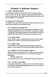
...follow the installation wizard to install it. 4.2.4 ASRock PC-DIY Live Demo Program ASRock presents you a multimedia PC-DIY live demo, which shows you need to contact ASRock or want to know more information. 4.2 Support CD Information The Support CD that came with the motherboard contains necessary drivers... and useful utilities that the motherboard supports. Click on the file ASSETUP.EXE from the BIN ...
...follow the installation wizard to install it. 4.2.4 ASRock PC-DIY Live Demo Program ASRock presents you a multimedia PC-DIY live demo, which shows you need to contact ASRock or want to know more information. 4.2 Support CD Information The Support CD that came with the motherboard contains necessary drivers... and useful utilities that the motherboard supports. Click on the file ASSETUP.EXE from the BIN ...
User Manual
Page 3
... Menu 30 3. Exit Menu 33 3 Contents 1 Introduction 4 1.1 Package Contents 4 1.2 Specifications 5 1.3 Motherboard Layout 7 1.4 ASRock I/O PlusTM 8 2 Installation 9 2.1 Screw Holes 9 2.2 Pre-installation Precautions 9 2.3 CPU Installation 10 2.4 Installation of CPU...22 3.3 Advanced, Security, Power, Boot, and Exit Menus ..... 24 4 Software Support 25 4.1 Install Operating System 25 4.2 Support CD Information 25 4.2.1 Running Support CD 25 4.2.2 Drivers Menu 25 4.2.3 Utilities Menu 25 4.2.4 ASRock "PC-DIY Live Demo" Program 25 4.2.5 Contact Information 25 Appendix 26 1. ...
... Menu 30 3. Exit Menu 33 3 Contents 1 Introduction 4 1.1 Package Contents 4 1.2 Specifications 5 1.3 Motherboard Layout 7 1.4 ASRock I/O PlusTM 8 2 Installation 9 2.1 Screw Holes 9 2.2 Pre-installation Precautions 9 2.3 CPU Installation 10 2.4 Installation of CPU...22 3.3 Advanced, Security, Power, Boot, and Exit Menus ..... 24 4 Software Support 25 4.1 Install Operating System 25 4.2 Support CD Information 25 4.2.1 Running Support CD 25 4.2.2 Drivers Menu 25 4.2.3 Utilities Menu 25 4.2.4 ASRock "PC-DIY Live Demo" Program 25 4.2.5 Contact Information 25 Appendix 26 1. ...
User Manual
Page 4
... DIY system builders. It delivers excellent performance with robust design conforming to ASRock's commitment to change without further notice. ASRock website http://www.asrock.com 1.1 Package Contents ASRock P4VT8 Motherboard (ATX Form Factor: 12.0-in x 7.5-in, 30.5 cm x 19.1 cm) ASRock P4VT8 Quick Installation Guide ASRock P4VT8 Support CD One 80-conductor Ultra ATA 66/100/133 IDE Ribbon Cable One...
... DIY system builders. It delivers excellent performance with robust design conforming to ASRock's commitment to change without further notice. ASRock website http://www.asrock.com 1.1 Package Contents ASRock P4VT8 Motherboard (ATX Form Factor: 12.0-in x 7.5-in, 30.5 cm x 19.1 cm) ASRock P4VT8 Quick Installation Guide ASRock P4VT8 Support CD One 80-conductor Ultra ATA 66/100/133 IDE Ribbon Cable One...
User Manual
Page 14
... vendor for internal storage devices. Serial ATA Connectors (SATA1: see p.7 item 12) (SATA2: see p.7 item 11) SATA2 SATA1 These two Serial ATA (SATA) connectors support SATA data cables for the details. Primary IDE Connector (Blue) Secondary IDE Connector (Black) (39-pin IDE1, see p.7 item 8) (39-pin IDE2, see p.7 ... (IDE2, black). Serial ATA (SATA) Data Cable Either end of your hard disk drive to the primary IDE connector (IDE1, blue) and CD-ROM to Pin1 Note: Make sure the red-striped side of the cable is plugged into Pin1 side of the connector. The current SATA interface...
... vendor for internal storage devices. Serial ATA Connectors (SATA1: see p.7 item 12) (SATA2: see p.7 item 11) SATA2 SATA1 These two Serial ATA (SATA) connectors support SATA data cables for the details. Primary IDE Connector (Blue) Secondary IDE Connector (Black) (39-pin IDE1, see p.7 item 8) (39-pin IDE2, see p.7 ... (IDE2, black). Serial ATA (SATA) Data Cable Either end of your hard disk drive to the primary IDE connector (IDE1, blue) and CD-ROM to Pin1 Note: Make sure the red-striped side of the cable is plugged into Pin1 side of the connector. The current SATA interface...
User Manual
Page 15
... 2.0 Header (9-pin USB4_5) (see p.7 item 19) USB_PWR P-7 P+7 GND DUMMY 1 GND P+6 P-6 USB_PWR ASRock I/O PlusTM provides you to function. O U T- This is available to this USB 2.0 header (USB67) is... audio devices. 15 When using the front panel USB ports by attaching the front panel USB cable to support 2 additional USB 2.0 ports. R MIC-POWER MIC These connectors allow you 6 default USB 2.0 ports on... CD1, 4-pin AUX1) (CD1: see p.7 item 30) (AUX1: see p.7 item 29) CD-L GND GND CD-R AUX-L GND GND AUX-R CD1 AUX1 Front Panel Audio Connector (9-pin AUDIO1) (see p.7 item 18...
... 2.0 Header (9-pin USB4_5) (see p.7 item 19) USB_PWR P-7 P+7 GND DUMMY 1 GND P+6 P-6 USB_PWR ASRock I/O PlusTM provides you to function. O U T- This is available to this USB 2.0 header (USB67) is... audio devices. 15 When using the front panel USB ports by attaching the front panel USB cable to support 2 additional USB 2.0 ports. R MIC-POWER MIC These connectors allow you 6 default USB 2.0 ports on... CD1, 4-pin AUX1) (CD1: see p.7 item 30) (AUX1: see p.7 item 29) CD-L GND GND CD-R AUX-L GND GND AUX-R CD1 AUX1 Front Panel Audio Connector (9-pin AUDIO1) (see p.7 item 18...
User Manual
Page 17
...SATA data cable to install the SATA hard disks. 2.9 Serial ATA (SATA) Hard Disks Installation This motherboard adopts VIA VT8237 southbridge chipset that supports Serial ATA (SATA) hard disks. Start to generate Serial ATA driver diskette [Y/N]?", press . This section will need to the motherboard's secondary SATA... 2: Connect one end of the SATA data cable to format the floppy diskette and copy SATA HDD drivers. STEP 1: Insert the ASRock Support CD into your system. (Do NOT insert any floppy diskette into the floppy drive WARNING! How to boot your optical drive to make an...
...SATA data cable to install the SATA hard disks. 2.9 Serial ATA (SATA) Hard Disks Installation This motherboard adopts VIA VT8237 southbridge chipset that supports Serial ATA (SATA) hard disks. Start to generate Serial ATA driver diskette [Y/N]?", press . This section will need to the motherboard's secondary SATA... 2: Connect one end of the SATA data cable to format the floppy diskette and copy SATA HDD drivers. STEP 1: Insert the ASRock Support CD into your system. (Do NOT insert any floppy diskette into the floppy drive WARNING! How to boot your optical drive to make an...
User Manual
Page 18
... install a third party SCSI or Raid driver...." Please verify the status of Windows 2000 or Windows XP, please insert Windows 2000 or Windows XP CD into the optical drive. 2.9.1 Installation of Windows 2000 / Windows XP For the installation of your hard disks. 18 At this moment, please press...system since it contains a complete copy of the same model and capacity when creating a RAID set is called data striping that integrates RAID controller supporting RAID 0 and RAID 1 with two independent Serial ATA (SATA) channels. RAID 1 RAID 1 is 60GB. 3. For example, if one drive to a ...
... install a third party SCSI or Raid driver...." Please verify the status of Windows 2000 or Windows XP, please insert Windows 2000 or Windows XP CD into the optical drive. 2.9.1 Installation of Windows 2000 / Windows XP For the installation of your hard disks. 18 At this moment, please press...system since it contains a complete copy of the same model and capacity when creating a RAID set is called data striping that integrates RAID controller supporting RAID 0 and RAID 1 with two independent Serial ATA (SATA) channels. RAID 1 RAID 1 is 60GB. 3. For example, if one drive to a ...
User Manual
Page 20
... your computer. If you wish to install the SATA hard disks and set the array mode as RAID 1, please refer to the file in the support CD: .. \ RAID SETUP \ RAID 1.PDF 20 If you wish to install the SATA hard disks alone without making RAID setup, please refer to the file... in the support CD: .. \ RAID SETUP \ SATA.PDF 2. STEP 3: Start the configuration from the menu and press . 5.1 Select the option Select Disk Drives, then press . Use arrow keys...
... your computer. If you wish to install the SATA hard disks and set the array mode as RAID 1, please refer to the file in the support CD: .. \ RAID SETUP \ RAID 1.PDF 20 If you wish to install the SATA hard disks alone without making RAID setup, please refer to the file... in the support CD: .. \ RAID SETUP \ SATA.PDF 2. STEP 3: Start the configuration from the menu and press . 5.1 Select the option Select Disk Drives, then press . Use arrow keys...
User Manual
Page 25
...ASRock, welcome to know more information. 4.2 Support CD Information The Support CD that came with the motherboard contains necessary drivers and useful utilities that the motherboard supports. or you need to contact ASRock or want to visit ASRock's website at http://www.asrock.com; Chapter 4 Software Support 4.1 Install Operating System This motherboard supports... Menu shows the applications software that enhance the motherboard features. 4.2.1 Running The Support CD To begin using the support CD, insert the CD into your own PC system step by step. Click on the file ASSETUP....
...ASRock, welcome to know more information. 4.2 Support CD Information The Support CD that came with the motherboard contains necessary drivers and useful utilities that the motherboard supports. or you need to contact ASRock or want to visit ASRock's website at http://www.asrock.com; Chapter 4 Software Support 4.1 Install Operating System This motherboard supports... Menu shows the applications software that enhance the motherboard features. 4.2.1 Running The Support CD To begin using the support CD, insert the CD into your own PC system step by step. Click on the file ASSETUP....


