User Manual
Page 13
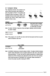
... system setup parameters. The data in CMOS. Note: To select +5VSB, it requires 2 Amp and higher standby current provided by power supply. To clear and reset the system parameters to default setup, please turn off the computer and unplug the power cord, then use a jumper cap to remove the jumper cap...
... system setup parameters. The data in CMOS. Note: To select +5VSB, it requires 2 Amp and higher standby current provided by power supply. To clear and reset the system parameters to default setup, please turn off the computer and unplug the power cord, then use a jumper cap to remove the jumper cap...

User Manual
Page 16
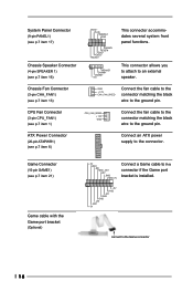
... fan cable to the connector matching the black wire to the ground pin. CPU Fan Connector (3-pin CPU_FAN1) (see p.7 item 16) PLED+ PLEDPWRBTN# GND 1 DUMMY RESET# GND HDLEDHDLED+ 1 SPEAKER DUMMY DUMMY +5V This connector accommodates several system front panel functions. Game Connector (15-pin GAME1) (see p.7 item 6) Connect an ATX power...
... fan cable to the connector matching the black wire to the ground pin. CPU Fan Connector (3-pin CPU_FAN1) (see p.7 item 16) PLED+ PLEDPWRBTN# GND 1 DUMMY RESET# GND HDLEDHDLED+ 1 SPEAKER DUMMY DUMMY +5V This connector accommodates several system front panel functions. Game Connector (15-pin GAME1) (see p.7 item 6) Connect an ATX power...
User Manual
Page 21
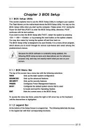
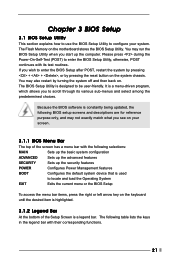
... with its various sub-menus and select among the predetermined choices. The BIOS Setup Utility is a legend bar. You may also restart by pressing the reset button on the system chassis. Please press during the Power-On-Self-Test (POST) to locate and load the Operating System EXIT Exits the current...
... with its various sub-menus and select among the predetermined choices. The BIOS Setup Utility is a legend bar. You may also restart by pressing the reset button on the system chassis. Please press during the Power-On-Self-Test (POST) to locate and load the Operating System EXIT Exits the current...
User Manual
Page 13
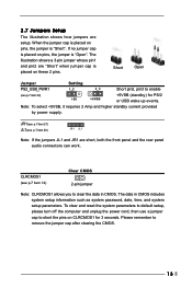
..., both the front panel and the rear panel audio connectors can work. CLRCMOS1 (see p.7 item 20) +5V +5VSB +5VSB (standby) for 3 seconds. To clear and reset the system parameters to default setup, please turn off the computer and unplug the power cord, then use a jumper cap to short the pins on...
..., both the front panel and the rear panel audio connectors can work. CLRCMOS1 (see p.7 item 20) +5V +5VSB +5VSB (standby) for 3 seconds. To clear and reset the system parameters to default setup, please turn off the computer and unplug the power cord, then use a jumper cap to short the pins on...
User Manual
Page 16
... supply to an external speaker. System Panel Connector (9-pin PANEL1) (see p.7 item 17) Chassis Speaker Connector (4-pin SPEAKER 1) (see p.7 item 16) PLED+ PLEDPWRBTN# GND 1 DUMMY RESET# GND HDLEDHDLED+ 1 SPEAKER DUMMY DUMMY +5V This connector accommodates several system front panel functions.
... supply to an external speaker. System Panel Connector (9-pin PANEL1) (see p.7 item 17) Chassis Speaker Connector (4-pin SPEAKER 1) (see p.7 item 16) PLED+ PLEDPWRBTN# GND 1 DUMMY RESET# GND HDLEDHDLED+ 1 SPEAKER DUMMY DUMMY +5V This connector accommodates several system front panel functions.
User Manual
Page 21
... bar. It is constantly being updated, the following BIOS setup screens and descriptions are for reference purpose only, and may also restart by pressing the reset button on the keyboard until the desired item is highlighted. 3.1.2 Legend Bar At the bottom of the screen has a menu bar with the following table...
... bar. It is constantly being updated, the following BIOS setup screens and descriptions are for reference purpose only, and may also restart by pressing the reset button on the keyboard until the desired item is highlighted. 3.1.2 Legend Bar At the bottom of the screen has a menu bar with the following table...


