
User Manual
Page 5
...in , 24.4 cm x 20.3 cm) ASRock P4VM890 Quick Installation Guide ASRock P4VM890 Support CD One 80-conductor Ultra ATA 66/100/133 IDE Ribbon Cable One Ribbon Cable for purchasing ASRock P4VM890 motherboard, a reliable motherboard produced under ASRock's consistently stringent quality control. 1. Chapter 3 and...introduction of the Support CD. You may find the latest VGA cards and CPU support lists on ASRock website without notice. ASRock website http://www.asrock.com 1.1 Package Contents ASRock P4VM890 Motherboard (Micro ATX Form Factor: 9.6-in x 8.0-in Floppy Drive One Serial ATA (SATA)...
...in , 24.4 cm x 20.3 cm) ASRock P4VM890 Quick Installation Guide ASRock P4VM890 Support CD One 80-conductor Ultra ATA 66/100/133 IDE Ribbon Cable One Ribbon Cable for purchasing ASRock P4VM890 motherboard, a reliable motherboard produced under ASRock's consistently stringent quality control. 1. Chapter 3 and...introduction of the Support CD. You may find the latest VGA cards and CPU support lists on ASRock website without notice. ASRock website http://www.asrock.com 1.1 Package Contents ASRock P4VM890 Motherboard (Micro ATX Form Factor: 9.6-in x 8.0-in Floppy Drive One Serial ATA (SATA)...

Quick Installation Guide
Page 1
... may appear in this device must accept any errors or omissions that may cause undesired operation. All rights reserved. 1 ASRock P4VM890 Motherboard English Operation is subject to the following two conditions: (1) this device may apply, see www.dtsc.ca.gov/hazardouswaste/perchlorate..." ASRock Website: http://www.asrock.com Published August 2007 Copyright©2007 ASRock INC. In no responsibility for loss of profits, loss of business, loss of data, interruption of business...
... may appear in this device must accept any errors or omissions that may cause undesired operation. All rights reserved. 1 ASRock P4VM890 Motherboard English Operation is subject to the following two conditions: (1) this device may apply, see www.dtsc.ca.gov/hazardouswaste/perchlorate..." ASRock Website: http://www.asrock.com Published August 2007 Copyright©2007 ASRock INC. In no responsibility for loss of profits, loss of business, loss of data, interruption of business...

Quick Installation Guide
Page 2
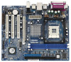
... Express x16 Slot (PCIE1) 27 Chassis Fan Connector (CHA_FAN1) 28 ATX Power Connector (ATXPWR1) 29 Shared USB 2.0 Header (USB4_5, Blue) 30 CPU Fan Connector (CPU_FAN1) 2 ASRock P4VM890 Motherboard
... Express x16 Slot (PCIE1) 27 Chassis Fan Connector (CHA_FAN1) 28 ATX Power Connector (ATXPWR1) 29 Shared USB 2.0 Header (USB4_5, Blue) 30 CPU Fan Connector (CPU_FAN1) 2 ASRock P4VM890 Motherboard

Quick Installation Guide
Page 3
ASRock I/O PlusTM 1 Parallel Port 2 RJ-45 Port 3 Line In (Light Blue) 4 Line Out (Lime) 5 Microphone (Pink) 6 Shared USB 2.0 Ports (USB45) 7 USB 2.0 Ports (USB01) 8 USB 2.0 Ports (USB23) 9 VGA Port 10 PS/2 Keyboard Port (Purple) 11 PS/2 Mouse Port (Green) English 3 ASRock P4VM890 Motherboard
ASRock I/O PlusTM 1 Parallel Port 2 RJ-45 Port 3 Line In (Light Blue) 4 Line Out (Lime) 5 Microphone (Pink) 6 Shared USB 2.0 Ports (USB45) 7 USB 2.0 Ports (USB01) 8 USB 2.0 Ports (USB23) 9 VGA Port 10 PS/2 Keyboard Port (Purple) 11 PS/2 Mouse Port (Green) English 3 ASRock P4VM890 Motherboard

Quick Installation Guide
Page 4
... quality and endurance. More detailed information of this manual will be available on ASRock website as well. 1. ASRock website http://www.asrock.com 1.1 Package Contents ASRock P4VM890 Motherboard (Micro ATX Form Factor: 9.6-in x 8.0-in, 24.4 cm x 20.3 cm) ASRock P4VM890 Quick Installation Guide ASRock P4VM890 Support CD One 80-conductor Ultra ATA 66/100/133 IDE Ribbon Cable One...
... quality and endurance. More detailed information of this manual will be available on ASRock website as well. 1. ASRock website http://www.asrock.com 1.1 Package Contents ASRock P4VM890 Motherboard (Micro ATX Form Factor: 9.6-in x 8.0-in, 24.4 cm x 20.3 cm) ASRock P4VM890 Quick Installation Guide ASRock P4VM890 Support CD One 80-conductor Ultra ATA 66/100/133 IDE Ribbon Cable One...

Quick Installation Guide
Page 5
... Untied Overclocking Technology (see CAUTION 3) - Southbridge: VIA® VT8237R Plus - 2 x DDR DIMM slots - DirectX 7.0 VGA - capacity: 2GB - Speed: 10/100 Ethernet - Supports Wake-On-LAN ASRock I /O Connector - 1.2 Specifications Platform CPU Chipset Memory Hybrid Booster Expansion Slot Graphics Audio LAN Rear Panel I /O PlusTM - 1 x PS/2 Mouse Port - 1 x PS/2 Keyboard Port - 1 x VGA... - 1 x RJ-45 LAN Port - Northbridge: VIA® P4M890 - Max. Audio Jack: Line in , 24.4 cm x 20.3 cm - CPU/Chassis FAN connector 5 ASRock P4VM890 Motherboard English
... Untied Overclocking Technology (see CAUTION 3) - Southbridge: VIA® VT8237R Plus - 2 x DDR DIMM slots - DirectX 7.0 VGA - capacity: 2GB - Speed: 10/100 Ethernet - Supports Wake-On-LAN ASRock I /O Connector - 1.2 Specifications Platform CPU Chipset Memory Hybrid Booster Expansion Slot Graphics Audio LAN Rear Panel I /O PlusTM - 1 x PS/2 Mouse Port - 1 x PS/2 Keyboard Port - 1 x VGA... - 1 x RJ-45 LAN Port - Northbridge: VIA® P4M890 - Max. Audio Jack: Line in , 24.4 cm x 20.3 cm - CPU/Chassis FAN connector 5 ASRock P4VM890 Motherboard English
Quick Installation Guide
Page 6
... AMI BIOS - We are shared with overclocking, including adjusting the setting in the BIOS, applying Untied Overclocking Technology, or using the thirdparty overclocking tools. English 6 ASRock P4VM890 Motherboard
... AMI BIOS - We are shared with overclocking, including adjusting the setting in the BIOS, applying Untied Overclocking Technology, or using the thirdparty overclocking tools. English 6 ASRock P4VM890 Motherboard

Quick Installation Guide
Page 7
... system, please check if the CPU fan on page 19 for USB 2.0 works fine under Microsoft® Windows® XP SP1 or SP2 / 2000 SP4. 7 ASRock P4VM890 Motherboard English Power Management for details. 3. CAUTION! 1. About the setting of "Hyper Threading Technology", please check page 26 of the system or damage the CPU. 4.
... system, please check if the CPU fan on page 19 for USB 2.0 works fine under Microsoft® Windows® XP SP1 or SP2 / 2000 SP4. 7 ASRock P4VM890 Motherboard English Power Management for details. 3. CAUTION! 1. About the setting of "Hyper Threading Technology", please check page 26 of the system or damage the CPU. 4.

Quick Installation Guide
Page 8
... not touch the ICs. 4. To avoid damaging the motherboard components due to the motherboard, peripherals, and/or components. 8 ASRock P4VM890 Motherboard English Unplug the power cord from the power supply. Pre-installation Precautions Take note of your motherboard directly on a grounded...Before you install the motherboard, study the configuration of the following precautions before you uninstall any motherboard settings. 1. Installation P4VM890 is detached from the wall socket before touching any component, ensure that comes with the component. 2. Before you install or ...
... not touch the ICs. 4. To avoid damaging the motherboard components due to the motherboard, peripherals, and/or components. 8 ASRock P4VM890 Motherboard English Unplug the power cord from the power supply. Pre-installation Precautions Take note of your motherboard directly on a grounded...Before you install the motherboard, study the configuration of the following precautions before you uninstall any motherboard settings. 1. Installation P4VM890 is detached from the wall socket before touching any component, ensure that comes with the component. 2. Before you install or ...

Quick Installation Guide
Page 9
Unlock the socket by lifting the lever up to dissipate heat. Step 2. The CPU fits only in place. English 9 ASRock P4VM890 Motherboard Position the CPU directly above the socket such that it is in good contact with each other. Carefully insert the CPU into the socket ...
Unlock the socket by lifting the lever up to dissipate heat. Step 2. The CPU fits only in place. English 9 ASRock P4VM890 Motherboard Position the CPU directly above the socket such that it is in good contact with each other. Carefully insert the CPU into the socket ...

Quick Installation Guide
Page 10
... slots. Unlock a DIMM slot by pressing the retaining clips outward. Step 2. Step 1. The DIMM only fits in place and the DIMM is properly seated. 10 ASRock P4VM890 Motherboard English Step 3. Please make sure to the motherboard and the DIMM if you force the DIMM into the slot until the retaining clips at...
... slots. Unlock a DIMM slot by pressing the retaining clips outward. Step 2. Step 1. The DIMM only fits in place and the DIMM is properly seated. 10 ASRock P4VM890 Motherboard English Step 3. Please make sure to the motherboard and the DIMM if you force the DIMM into the slot until the retaining clips at...

Quick Installation Guide
Page 11
... card with x16 lane width graphics cards. Align the card connector with screws. Fasten the card to use . Replace the system cover. 11 ASRock P4VM890 Motherboard English Installing an expansion card Step 1. Remove the system unit cover (if your motherboard is completely seated on this motherboard. Keep the screws for ...
... card with x16 lane width graphics cards. Align the card connector with screws. Fasten the card to use . Replace the system cover. 11 ASRock P4VM890 Motherboard English Installing an expansion card Step 1. Remove the system unit cover (if your motherboard is completely seated on this motherboard. Keep the screws for ...

Quick Installation Guide
Page 12
... for 15 seconds, use a jumper cap to default setup, please turn off the computer and unplug the power cord from the power supply. English 12 ASRock P4VM890 Motherboard To clear and reset the system parameters to short 2 pins on pins, the jumper is "Short". 2.5 Jumpers Setup The illustration shows how jumpers are...
... for 15 seconds, use a jumper cap to default setup, please turn off the computer and unplug the power cord from the power supply. English 12 ASRock P4VM890 Motherboard To clear and reset the system parameters to short 2 pins on pins, the jumper is "Short". 2.5 Jumpers Setup The illustration shows how jumpers are...

Quick Installation Guide
Page 13
...-striped side to the IDE devices 80-conductor ATA 66/100/133 cable Note: If you use only one IDE device on the motherboard. 13 ASRock P4VM890 Motherboard English Do NOT place jumper caps over the headers and connectors will cause permanent damage of your hard disk drive to the primary IDE...
...-striped side to the IDE devices 80-conductor ATA 66/100/133 cable Note: If you use only one IDE device on the motherboard. 13 ASRock P4VM890 Motherboard English Do NOT place jumper caps over the headers and connectors will cause permanent damage of your hard disk drive to the primary IDE...
Quick Installation Guide
Page 14
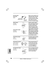
... audio devices. This header supports an optional wireless transmitting and receiving infrared module. This is shared with USB ports 45 on the I /O panel. English 14 ASRock P4VM890 Motherboard Serial ATA (SATA) Power Cable (Optional) connect to the SATA HDD power connector connect to the power supply USB 2.0 Header (9-pin USB67) (see p.2, No...
... audio devices. This header supports an optional wireless transmitting and receiving infrared module. This is shared with USB ports 45 on the I /O panel. English 14 ASRock P4VM890 Motherboard Serial ATA (SATA) Power Cable (Optional) connect to the SATA HDD power connector connect to the power supply USB 2.0 Header (9-pin USB67) (see p.2, No...

Quick Installation Guide
Page 15
...) Please connect the chassis speaker to this connector and match the black wire to the ground pin. otherwise, it can provides sufficient power. English 15 ASRock P4VM890 Motherboard Please connect an ATX power supply to this connector and match the black wire to the ground pin. System Panel Header (9-pin PANEL1) (see...
...) Please connect the chassis speaker to this connector and match the black wire to the ground pin. otherwise, it can provides sufficient power. English 15 ASRock P4VM890 Motherboard Please connect an ATX power supply to this connector and match the black wire to the ground pin. System Panel Header (9-pin PANEL1) (see...

Quick Installation Guide
Page 16
...this motherboard for SATA Devices. Therefore, the drivers you to the SATA hard disk. 2.8 Hot Plug and Hot Swap Functions for SATA HDDs P4VM890 motherboard supports Hot Plug and Hot Swap functions for internal storage devices. STEP 1: Install the SATA hard disks into the SATA HDD. 2.7 ...chipset that it cannot perform Hot Plug if the OS has been installed into the drive bays of your system can work properly. 16 ASRock P4VM890 Motherboard English Then, the drivers compatible to the motherboard's SATA connector. You may install SATA hard disks on the support CD driver page...
...this motherboard for SATA Devices. Therefore, the drivers you to the SATA hard disk. 2.8 Hot Plug and Hot Swap Functions for SATA HDDs P4VM890 motherboard supports Hot Plug and Hot Swap functions for internal storage devices. STEP 1: Install the SATA hard disks into the SATA HDD. 2.7 ...chipset that it cannot perform Hot Plug if the OS has been installed into the drive bays of your system can work properly. 16 ASRock P4VM890 Motherboard English Then, the drivers compatible to the motherboard's SATA connector. You may install SATA hard disks on the support CD driver page...

Quick Installation Guide
Page 17
... to configure RAID function, you plan to use AMR card function on this motherboard. A. B. ROM as the boot device. When you install. 17 ASRock P4VM890 Motherboard English D. Install AMR card driver from our support CD to your system. E. Before you start to format the floppy diskette and copy SATA drivers... the RAID installation guide in the Support CD: .. \ RAID Installation Guide STEP 4: Install Windows® 2000 / XP OS on the slot. 2. Insert the ASRock Support CD into the floppy diskette. Enter BIOS SETUP UTILITY Advanced screen IDE Configuration.
... to configure RAID function, you plan to use AMR card function on this motherboard. A. B. ROM as the boot device. When you install. 17 ASRock P4VM890 Motherboard English D. Install AMR card driver from our support CD to your system. E. Before you start to format the floppy diskette and copy SATA drivers... the RAID installation guide in the Support CD: .. \ RAID Installation Guide STEP 4: Install Windows® 2000 / XP OS on the slot. 2. Insert the ASRock Support CD into the floppy diskette. Enter BIOS SETUP UTILITY Advanced screen IDE Configuration.

Quick Installation Guide
Page 18
... as well. 2.12 Installing Windows® 2000 / XP Without RAID Functions If you can start to use "VIA RAID Tool" in BIOS first. B. English 18 ASRock P4VM890 Motherboard STEP 1: Set up "SATA Operation Mode" to [RAID] in Windows® environment, please install SATA drivers from the Support CD again so that "VIA...
... as well. 2.12 Installing Windows® 2000 / XP Without RAID Functions If you can start to use "VIA RAID Tool" in BIOS first. B. English 18 ASRock P4VM890 Motherboard STEP 1: Set up "SATA Operation Mode" to [RAID] in Windows® environment, please install SATA drivers from the Support CD again so that "VIA...

Quick Installation Guide
Page 19
... folder in the fixed mode so that will display the Main Menu automatically if "AUTORUN" is in the Support CD to display the menus. 19 ASRock P4VM890 Motherboard English It is designed to be user-friendly. 2.13 Untied Overclocking Technology This motherboard supports Untied Overclocking Technology, which means during the Power-On...
... folder in the fixed mode so that will display the Main Menu automatically if "AUTORUN" is in the Support CD to display the menus. 19 ASRock P4VM890 Motherboard English It is designed to be user-friendly. 2.13 Untied Overclocking Technology This motherboard supports Untied Overclocking Technology, which means during the Power-On...


