User Manual
Page 4
... 41 3.1 Introduction 41 3.1.1 BIOS Menu Bar 41 3.1.2 Navigation Keys 42 3.2 Main Screen 42 3.3 Advanced Screen 44 3.3.1 CPU Configuration 44 3.3.2 Chipset Configuration 47 3.3.3 ACPI Configuration 50 3.3.4 IDE Configuration 51 3.3.5 PCIPnP ...
... 41 3.1 Introduction 41 3.1.1 BIOS Menu Bar 41 3.1.2 Navigation Keys 42 3.2 Main Screen 42 3.3 Advanced Screen 44 3.3.1 CPU Configuration 44 3.3.2 Chipset Configuration 47 3.3.3 ACPI Configuration 50 3.3.4 IDE Configuration 51 3.3.5 PCIPnP ...
User Manual
Page 5
... a 3.5-in , 30.5 cm x 24.4 cm) ASRock P43D1600Twins-1394 / P43D1600Twins / P43Twins1600 Quick Installation Guide ASRock P43D1600Twins-1394 / P43D1600Twins / P43Twins1600 Support CD One 80-conductor Ultra ATA 66/100/133 IDE Ribbon Cable One Ribbon Cable for purchasing ASRock P43D1600Twins-1394 / P43D1600Twins / P43Twins1600 motherboard, a reliable motherboard produced under ASRock's consistently stringent quality control. Because the motherboard specifications and the BIOS software might be updated, the content...
... a 3.5-in , 30.5 cm x 24.4 cm) ASRock P43D1600Twins-1394 / P43D1600Twins / P43Twins1600 Quick Installation Guide ASRock P43D1600Twins-1394 / P43D1600Twins / P43Twins1600 Support CD One 80-conductor Ultra ATA 66/100/133 IDE Ribbon Cable One Ribbon Cable for purchasing ASRock P43D1600Twins-1394 / P43D1600Twins / P43Twins1600 motherboard, a reliable motherboard produced under ASRock's consistently stringent quality control. Because the motherboard specifications and the BIOS software might be updated, the content...

User Manual
Page 7
...- 24 pin ATX power connector - 8 pin 12V power connector (P43D1600Twins-1394 / P43D1600Twins) - 4 pin 12V power connector (P43Twins1600) - Supports "Plug and Play" - AMI Legal BIOS - CD in /Front Speaker/Microphone (see CAUTION 9) - 1 x...P43D1600Twins / P43Twins1600 ASRock SPDIF I/O - 1 x PS/2 Mouse Port - 1 x PS/2 Keyboard Port - 1 x Coaxial SPDIF Out Port - 1 x Optical SPDIF Out Port - 6 x Ready-to-Use USB 2.0 Ports - 1 x eSATAII Port - 1 x RJ-45 LAN Port with LED (ACT/LINK LED and SPEED LED) (P43D1600Twins) - 1 x RJ-45 LAN Port (P43Twins1600) - Connector BIOS Feature - 1 x IEEE 1394...
...- 24 pin ATX power connector - 8 pin 12V power connector (P43D1600Twins-1394 / P43D1600Twins) - 4 pin 12V power connector (P43Twins1600) - Supports "Plug and Play" - AMI Legal BIOS - CD in /Front Speaker/Microphone (see CAUTION 9) - 1 x...P43D1600Twins / P43Twins1600 ASRock SPDIF I/O - 1 x PS/2 Mouse Port - 1 x PS/2 Keyboard Port - 1 x Coaxial SPDIF Out Port - 1 x Optical SPDIF Out Port - 6 x Ready-to-Use USB 2.0 Ports - 1 x eSATAII Port - 1 x RJ-45 LAN Port with LED (ACT/LINK LED and SPEED LED) (P43D1600Twins) - 1 x RJ-45 LAN Port (P43Twins1600) - Connector BIOS Feature - 1 x IEEE 1394...

User Manual
Page 8
... (see CAUTION 12) - FCC, CE, WHQL * For detailed product information, please visit our website: http://www.asrock.com WARNING Please realize that there is a certain risk involved with overclocking, including adjusting the setting in the BIOS, applying Untied Overclocking Technology, or using the thirdparty overclocking tools. Drivers, Utilities, AntiVirus Software (Trial Version...
... (see CAUTION 12) - FCC, CE, WHQL * For detailed product information, please visit our website: http://www.asrock.com WARNING Please realize that there is a certain risk involved with overclocking, including adjusting the setting in the BIOS, applying Untied Overclocking Technology, or using the thirdparty overclocking tools. Drivers, Utilities, AntiVirus Software (Trial Version...
User Manual
Page 11
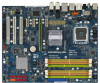
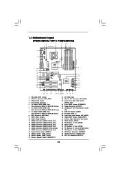
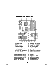
...Dual Channel C: DDR3_A1, DDR3_B1; Yellow) 6 2 x 240-pin DDR2 DIMM Slots (Dual Channel B: DDRII_A2, DDRII_B2; 1.4 Motherboard Layout (P43D1600Twins-1394 / P43D1600Twins) 12 3 4 56 7 24.4cm (9.6 in) PS2 Mouse PS2 Keyboard 40 1 PS2_USB_PWR1 Coaxial SPDIF Optical SPDIF 39 38 37 36... 1 HDMI_SPDIF1 1 HD_AUDIO1 COM1 1 PCIE3 PCIE2 PCI Express 2.0 1 FSB3 1 FSB2 PCIE4 1 FSB1 1 WIFI/E PCI1 RoHS PCI2 CMOS Battery 8Mb BIOS VIA VT6308S Intel ICH10 SATAII_5 (Port4) SATAII_3 (Port2) SATAII_1 (Port0) SATAII_6 (Port5) SATAII_4 (Port3) SATAII_2 (Port1) PCI3 IR1 1 FLOPPY1 CLRCMOS1...
...Dual Channel C: DDR3_A1, DDR3_B1; Yellow) 6 2 x 240-pin DDR2 DIMM Slots (Dual Channel B: DDRII_A2, DDRII_B2; 1.4 Motherboard Layout (P43D1600Twins-1394 / P43D1600Twins) 12 3 4 56 7 24.4cm (9.6 in) PS2 Mouse PS2 Keyboard 40 1 PS2_USB_PWR1 Coaxial SPDIF Optical SPDIF 39 38 37 36... 1 HDMI_SPDIF1 1 HD_AUDIO1 COM1 1 PCIE3 PCIE2 PCI Express 2.0 1 FSB3 1 FSB2 PCIE4 1 FSB1 1 WIFI/E PCI1 RoHS PCI2 CMOS Battery 8Mb BIOS VIA VT6308S Intel ICH10 SATAII_5 (Port4) SATAII_3 (Port2) SATAII_1 (Port0) SATAII_6 (Port5) SATAII_4 (Port3) SATAII_2 (Port1) PCI3 IR1 1 FLOPPY1 CLRCMOS1...
User Manual
Page 12
... Header (PANEL1) 18 USB 2.0 Header (USB4_5, Blue) 19 USB 2.0 Header (USB6_7, Blue) 20 Chassis Speaker Header (SPEAKER 1) 21 SPI BIOS Chip 22 Chassis Fan Connector (CHA_FAN1) 23 Clear CMOS Jumper (CLRCMOS1) 24 Floppy Connector (FLOPPY1) 25 DeskExpress Hot Plug Detection Header (IR1) 26... RoHS PCI2 PCI3 IR1 1 FLOPPY1 CLRCMOS1 1 SATAII_5 (Port4) SATAII_3 (Port2) SATAII_1 (Port0) SATAII_6 (Port5) SATAII_4 (Port3) SATAII_2 (Port1) CMOS Battery 4Mb BIOS VIA VT6308S Intel ICH10 CHA_FAN1 SPEAKER1 1 USB6_7 1 USB4_5 1 PLED PWRBTN 1 PANEL1 HDLED RESET 30.5cm (12.0 in) 8 9 10 11 12 13 14...
... Header (PANEL1) 18 USB 2.0 Header (USB4_5, Blue) 19 USB 2.0 Header (USB6_7, Blue) 20 Chassis Speaker Header (SPEAKER 1) 21 SPI BIOS Chip 22 Chassis Fan Connector (CHA_FAN1) 23 Clear CMOS Jumper (CLRCMOS1) 24 Floppy Connector (FLOPPY1) 25 DeskExpress Hot Plug Detection Header (IR1) 26... RoHS PCI2 PCI3 IR1 1 FLOPPY1 CLRCMOS1 1 SATAII_5 (Port4) SATAII_3 (Port2) SATAII_1 (Port0) SATAII_6 (Port5) SATAII_4 (Port3) SATAII_2 (Port1) CMOS Battery 4Mb BIOS VIA VT6308S Intel ICH10 CHA_FAN1 SPEAKER1 1 USB6_7 1 USB4_5 1 PLED PWRBTN 1 PANEL1 HDLED RESET 30.5cm (12.0 in) 8 9 10 11 12 13 14...
User Manual
Page 23
... are setup. After waiting for 15 seconds, use jumper to force NB to clear the CMOS when you just finish updating the BIOS, you must boot up events. The data in CMOS. Note: To select +5VSB, it down before you may face the ...+5V +5VSB or USB wake up the system first, and then shut it requires 2 Amp and higher standby current provided by BIOS setting) you do not clear the CMOS right after you to default setup, please turn off the computer and unplug the power...(see p.11, No. 24 or p.12, No. 23) 1_2 Default 2_3 Clear CMOS Note: CLRCMOS1 allows you update the BIOS.
... are setup. After waiting for 15 seconds, use jumper to force NB to clear the CMOS when you just finish updating the BIOS, you must boot up events. The data in CMOS. Note: To select +5VSB, it down before you may face the ...+5V +5VSB or USB wake up the system first, and then shut it requires 2 Amp and higher standby current provided by BIOS setting) you do not clear the CMOS right after you to default setup, please turn off the computer and unplug the power...(see p.11, No. 24 or p.12, No. 23) 1_2 Default 2_3 Clear CMOS Note: CLRCMOS1 allows you update the BIOS.
User Manual
Page 27
...-R CD1 This connector allows you to receive stereo audio input from [Auto] to Ground (GND). Please follow the instruction in the Realtek Control panel. B. Enter BIOS Setup Utility. For Windows® 2000 / XP / XP 64-bit OS: Please select "Front Mic" as a CD-ROM, DVD-ROM, TV tuner card, or MPEG...
...-R CD1 This connector allows you to receive stereo audio input from [Auto] to Ground (GND). Please follow the instruction in the Realtek Control panel. B. Enter BIOS Setup Utility. For Windows® 2000 / XP / XP 64-bit OS: Please select "Front Mic" as a CD-ROM, DVD-ROM, TV tuner card, or MPEG...
User Manual
Page 31
... 400Mb/s. NOTE: 1. Currently, on and in the near future, eSATAII will replace USB 2.0 and IEEE 1394 to 42 for IEEE 1394 is supported with Hot Plug capability that enables you set "Configure SATAII as " option in BIOS setup to 480Mb/s, and for detailed information of IDE mode and AHCI mode. SATAII connector SATAII_6...
... 400Mb/s. NOTE: 1. Currently, on and in the near future, eSATAII will replace USB 2.0 and IEEE 1394 to 42 for IEEE 1394 is supported with Hot Plug capability that enables you set "Configure SATAII as " option in BIOS setup to 480Mb/s, and for detailed information of IDE mode and AHCI mode. SATAII connector SATAII_6...
User Manual
Page 38
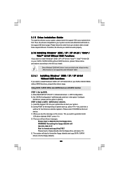
... 64-bit Without RAID Functions If you want to install Windows® 2000 / XP / XP 64-bit OS on the support CD driver page. Enter BIOS SETUP UTILITY Advanced screen IDE Configuration. C. Start to install Windows® 2000 / XP / XP 64-bit / VistaTM / VistaTM 64-bit OS on ... system. Then, the drivers compatible to [Enhanced], and then in it! Using SATA / SATAII HDDs and eSATAII devices with NCQ function STEP 1: Set Up BIOS. B. Set "SATAII Configuration" to your SATA / SATAII HDDs without RAID functions, please follow the order from up , press key, and then a window ...
... 64-bit Without RAID Functions If you want to install Windows® 2000 / XP / XP 64-bit OS on the support CD driver page. Enter BIOS SETUP UTILITY Advanced screen IDE Configuration. C. Start to install Windows® 2000 / XP / XP 64-bit / VistaTM / VistaTM 64-bit OS on ... system. Then, the drivers compatible to [Enhanced], and then in it! Using SATA / SATAII HDDs and eSATAII devices with NCQ function STEP 1: Set Up BIOS. B. Set "SATAII Configuration" to your SATA / SATAII HDDs without RAID functions, please follow the order from up , press key, and then a window ...
User Manual
Page 39
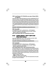
...of Windows® setup, press F6 to load the Intel® AHCI drivers. You may select: "Intel(R) ICH10 SATA AHCI Controller (Desktop - B. Enter BIOS SETUP UTILITY Advanced screen IDE Configuration. Set "SATAII Configuration" to [Enhanced], and then in the option "Configure SATAII as ", please set the option to [... When you see "Where do you can start to install Windows® XP / XP 64-bit on your system. page, please insert the ASRock Support CD into your optical drive, and click the "Load Driver" button on the left on the bottom to install a thirdparty AHCI driver. Enter...
...of Windows® setup, press F6 to load the Intel® AHCI drivers. You may select: "Intel(R) ICH10 SATA AHCI Controller (Desktop - B. Enter BIOS SETUP UTILITY Advanced screen IDE Configuration. Set "SATAII Configuration" to [Enhanced], and then in the option "Configure SATAII as ", please set the option to [... When you see "Where do you can start to install Windows® XP / XP 64-bit on your system. page, please insert the ASRock Support CD into your optical drive, and click the "Load Driver" button on the left on the bottom to install a thirdparty AHCI driver. Enter...
User Manual
Page 40
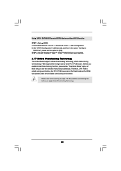
... B. A. Set "SATAII Configuration" to [Enhanced], and then in the fixed mode so that FSB can operate under a more stable overclocking environment. Enter BIOS SETUP UTILITY Advanced screen IDE Configuration. Before you apply Untied Overclocking Technology. 40 STEP 2: Install Windows® VistaTM / VistaTM 64-bit OS on page ...8 for the possible overclocking risk before you enable Untied Overclocking function, please enter "Overclock Mode" option of BIOS setup to set the option to [Manual]. Using SATA / SATAII HDDs and eSATAII devices without NCQ function STEP 1: Set up...
... B. A. Set "SATAII Configuration" to [Enhanced], and then in the fixed mode so that FSB can operate under a more stable overclocking environment. Enter BIOS SETUP UTILITY Advanced screen IDE Configuration. Before you apply Untied Overclocking Technology. 40 STEP 2: Install Windows® VistaTM / VistaTM 64-bit OS on page ...8 for the possible overclocking risk before you enable Untied Overclocking function, please enter "Overclock Mode" option of BIOS setup to set the option to [Manual]. Using SATA / SATAII HDDs and eSATAII devices without NCQ function STEP 1: Set up...
User Manual
Page 41
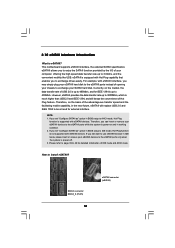
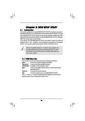
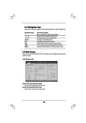
..., restart the system by pressing + + , or by turning the system off and then back on. You may run the BIOS SETUP UTILITY when you see on the system chassis. Because the BIOS software is constantly being updated, the following selections: Main To set up the system time/date information Advanced To set... H/W Monitor To display current hardware status Boot To set up the default system device to get into the sub screen. 41 The BIOS FWH chip on the menu bar, and then press to locate and load the Operating System Security To set up the computer. You may not ...
..., restart the system by pressing + + , or by turning the system off and then back on. You may run the BIOS SETUP UTILITY when you see on the system chassis. Because the BIOS software is constantly being updated, the following selections: Main To set up the system time/date information Advanced To set... H/W Monitor To display current hardware status Boot To set up the default system device to get into the sub screen. 41 The BIOS FWH chip on the menu bar, and then press to locate and load the Operating System Security To set up the computer. You may not ...
User Manual
Page 42
...overview. System Time [Hour:Minute:Second] Use this item to specify the system date. 42 Use [+] or [-] to select a field. P43D1600Twins-1394 BIOS SETUP UTILITY Main Advanced H/W Monitor Boot Security Exit System Overview System Time System Date [14:00:09] [Wed 04/30/2008...] BIOS Version : P43D1600Twins-1394 P1.00 Processor Type : Intel (R) Core(TM)2 Duo CPU E7300 @ 2.66GHz (64bit) Processor Speed : 2666MHz Microcode Update : 10676/60B Cache ...
...overview. System Time [Hour:Minute:Second] Use this item to specify the system date. 42 Use [+] or [-] to select a field. P43D1600Twins-1394 BIOS SETUP UTILITY Main Advanced H/W Monitor Boot Security Exit System Overview System Time System Date [14:00:09] [Wed 04/30/2008...] BIOS Version : P43D1600Twins-1394 P1.00 Processor Type : Intel (R) Core(TM)2 Duo CPU E7300 @ 2.66GHz (64bit) Processor Speed : 2666MHz Microcode Update : 10676/60B Cache ...
User Manual
Page 43
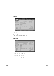
... UTILITY Main Advanced H/W Monitor Boot Security Exit System Overview System Time System Date [14:00:09] [Wed 04/30/2008] BIOS Version : P43D1600Twins P1.00 Processor Type : Intel (R) Core(TM)2 Duo CPU E7300 @ 2.66GHz (64bit) Processor Speed : 2666MHz Microcode Update : 10676/60B Cache Size : ... Use [Enter], [TAB] or [SHIFT-TAB] to select a field. System Time [Hour:Minute:Second] Use this item to specify the system time. P43Twins1600 BIOS SETUP UTILITY Main Advanced H/W Monitor Boot Security Exit System Overview System Time System Date [14:00:09] [Wed 04/30/2008...
... UTILITY Main Advanced H/W Monitor Boot Security Exit System Overview System Time System Date [14:00:09] [Wed 04/30/2008] BIOS Version : P43D1600Twins P1.00 Processor Type : Intel (R) Core(TM)2 Duo CPU E7300 @ 2.66GHz (64bit) Processor Speed : 2666MHz Microcode Update : 10676/60B Cache Size : ... Use [Enter], [TAB] or [SHIFT-TAB] to select a field. System Time [Hour:Minute:Second] Use this item to specify the system time. P43Twins1600 BIOS SETUP UTILITY Main Advanced H/W Monitor Boot Security Exit System Overview System Time System Date [14:00:09] [Wed 04/30/2008...
User Manual
Page 44
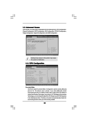
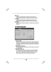
.... 3.3 Advanced Screen In this to select Overclock Mode. Setting wrong values in this section may cause system to malfunction. 3.3.1CPU Configuration BIOS SETUP UTILITY Advanced CPU Configuration Overclock Mode CPU Frequency (MHz) PCIE Frequency (MHz) Boot Failure Guard Spread Spectrum [Auto] [266] ... Item Change Option General Help Load Defaults Save and Exit Exit v02.54 (C) Copyright 1985-2005, American Megatrends, Inc. BIOS SETUP UTILITY Main Advanced H/W Monitor Boot Security Exit Advanced Settings WARNING : Setting wrong values in the following items: CPU Configuration...
.... 3.3 Advanced Screen In this to select Overclock Mode. Setting wrong values in this section may cause system to malfunction. 3.3.1CPU Configuration BIOS SETUP UTILITY Advanced CPU Configuration Overclock Mode CPU Frequency (MHz) PCIE Frequency (MHz) Boot Failure Guard Spread Spectrum [Auto] [266] ... Item Change Option General Help Load Defaults Save and Exit Exit v02.54 (C) Copyright 1985-2005, American Megatrends, Inc. BIOS SETUP UTILITY Main Advanced H/W Monitor Boot Security Exit Advanced Settings WARNING : Setting wrong values in the following items: CPU Configuration...
User Manual
Page 47
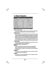
... This controls the number of overlapped PCI memory above the total physical memory. Standard Memory Info : 4-15-5-5-5-26-3-3-3 DRAM tCL Use this motherboard. 3.3.2Chipset Configuration BIOS SETUP UTILITY Advanced Chipset Configuration Memory Remap Feature [Disabled] DRAM Frequency [Auto] Flexibility Option [Disabled] Standard Memory Info : 4-15-5-5-5-26-3-3-3 DRAM tCL [Auto] DRAM tRAS...
... This controls the number of overlapped PCI memory above the total physical memory. Standard Memory Info : 4-15-5-5-5-26-3-3-3 DRAM tCL Use this motherboard. 3.3.2Chipset Configuration BIOS SETUP UTILITY Advanced Chipset Configuration Memory Remap Feature [Disabled] DRAM Frequency [Auto] Flexibility Option [Disabled] Standard Memory Info : 4-15-5-5-5-26-3-3-3 DRAM tCL [Auto] DRAM tRAS...
User Manual
Page 50
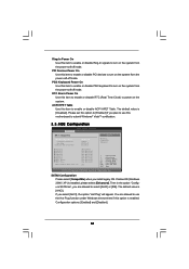
...]. Configuration options: [Auto], [Low], [Middle], [High] and [Highest]. Suspend to auto-detect or disable the Suspend-toRAM feature. If [Power Off] is [Enabled]. 3.3.3 ACPI Configuration BIOS SETUP UTILITY Advanced ACPI Configuration Suspend To RAM Repost Video on STR Resume Restore on AC/Power Loss This allows you to repost video on...
...]. Configuration options: [Auto], [Low], [Middle], [High] and [Highest]. Suspend to auto-detect or disable the Suspend-toRAM feature. If [Power Off] is [Enabled]. 3.3.3 ACPI Configuration BIOS SETUP UTILITY Advanced ACPI Configuration Suspend To RAM Repost Video on STR Resume Restore on AC/Power Loss This allows you to repost video on...
User Manual
Page 51
... turn on the system from the power-soft-off mode. PS/2 Keyboard Power On Use this motherboard to submit Windows® VistaTM certification. 3.3.4IDE Configuration BIOS SETUP UTILITY Advanced IDE Configuration SATAII Configuration Configure SATAII as ", you plan to use the Hot Plug function under Windows environment if this option is...
... turn on the system from the power-soft-off mode. PS/2 Keyboard Power On Use this motherboard to submit Windows® VistaTM certification. 3.3.4IDE Configuration BIOS SETUP UTILITY Advanced IDE Configuration SATAII Configuration Configure SATAII as ", you plan to use the Hot Plug function under Windows environment if this option is...
User Manual
Page 52
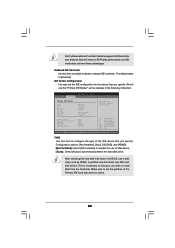
BIOS SETUP UTILITY Advanced Primary IDE Master Device Vendor Size LBA Mode Block Mode PIO Mode Async DMA Ultra DMA S.M.A.R.T. Configuration options: [Not Installed], [Auto], [CD/... these advantages. This is [Enabled]. OnBoard IDE Controller Use this item to enable or disable onboard IDE controller. After selecting the hard disk information into BIOS, use a disk utility, such as the example in the following instruction. TYPE Use this item to configure the type of the IDE device that you...
BIOS SETUP UTILITY Advanced Primary IDE Master Device Vendor Size LBA Mode Block Mode PIO Mode Async DMA Ultra DMA S.M.A.R.T. Configuration options: [Not Installed], [Auto], [CD/... these advantages. This is [Enabled]. OnBoard IDE Controller Use this item to enable or disable onboard IDE controller. After selecting the hard disk information into BIOS, use a disk utility, such as the example in the following instruction. TYPE Use this item to configure the type of the IDE device that you...


