User Manual
Page 2
... warranties or conditions of merchantability or fitness for a particular purpose. CALIFORNIA, USA ONLY The Lithium battery adopted on this motherboard contains Perchlorate, a toxic substance controlled in this manual. "Perchlorate Material-special handling may appear in Perchlorate Best Management Practices (BMP)... in any form or by any means, except duplication of documentation by the purchaser for backup purpose, without written consent of ASRock Inc. When you discard the Lithium battery in California, USA, please follow the related regulations in the manual or product. ...
... warranties or conditions of merchantability or fitness for a particular purpose. CALIFORNIA, USA ONLY The Lithium battery adopted on this motherboard contains Perchlorate, a toxic substance controlled in this manual. "Perchlorate Material-special handling may appear in Perchlorate Best Management Practices (BMP)... in any form or by any means, except duplication of documentation by the purchaser for backup purpose, without written consent of ASRock Inc. When you discard the Lithium battery in California, USA, please follow the related regulations in the manual or product. ...
User Manual
Page 3
Contents 1 Introduction 5 1.1 Package Contents 5 1.2 Specifications 6 1.3 Minimum Hardware Requirement Table for Windows® VistaTM Premium 2008 and Basic Logo 10 1.4 Motherboard Layout (P43D1600Twins-1394 / P43D1600Twins 11 1.5 Motherboard Layout (P43Twins1600 12 1.6 ASRock 1394_SPDIF I/O (P43D1600Twins-1394 13 1.7 ASRock SPDIF I/O (P43D1600Twins 14 1.8 ASRock SPDIF I/O (P43Twins1600 15 2 Installation 16 2.1 Screw Holes 16 2.2 Pre-installation Precautions 16 2.3 CPU Installation 17 2.4 Installation of Heatsink and CPU fan 19 2.5 Installation...
Contents 1 Introduction 5 1.1 Package Contents 5 1.2 Specifications 6 1.3 Minimum Hardware Requirement Table for Windows® VistaTM Premium 2008 and Basic Logo 10 1.4 Motherboard Layout (P43D1600Twins-1394 / P43D1600Twins 11 1.5 Motherboard Layout (P43Twins1600 12 1.6 ASRock 1394_SPDIF I/O (P43D1600Twins-1394 13 1.7 ASRock SPDIF I/O (P43D1600Twins 14 1.8 ASRock SPDIF I/O (P43Twins1600 15 2 Installation 16 2.1 Screw Holes 16 2.2 Pre-installation Precautions 16 2.3 CPU Installation 17 2.4 Installation of Heatsink and CPU fan 19 2.5 Installation...
User Manual
Page 5
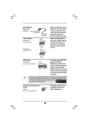
... and endurance. www.asrock.com/support/index.asp 1.1 Package Contents ASRock P43D1600Twins-1394 / P43D1600Twins / P43Twins1600 Motherboard (ATX Form Factor: 12.0-in x 9.6-in, 30.5 cm x 24.4 cm) ASRock P43D1600Twins-1394 / P43D1600Twins / P43Twins1600 Quick Installation Guide ASRock P43D1600Twins-1394 / P43D1600Twins / P43Twins1600 Support CD One 80-conductor Ultra ATA 66/100/133 IDE Ribbon Cable One Ribbon Cable for purchasing ASRock P43D1600Twins-1394 / P43D1600Twins / P43Twins1600 motherboard, a reliable motherboard produced under ASRock's consistently stringent quality...
... and endurance. www.asrock.com/support/index.asp 1.1 Package Contents ASRock P43D1600Twins-1394 / P43D1600Twins / P43Twins1600 Motherboard (ATX Form Factor: 12.0-in x 9.6-in, 30.5 cm x 24.4 cm) ASRock P43D1600Twins-1394 / P43D1600Twins / P43Twins1600 Quick Installation Guide ASRock P43D1600Twins-1394 / P43D1600Twins / P43Twins1600 Support CD One 80-conductor Ultra ATA 66/100/133 IDE Ribbon Cable One Ribbon Cable for purchasing ASRock P43D1600Twins-1394 / P43D1600Twins / P43Twins1600 motherboard, a reliable motherboard produced under ASRock's consistently stringent quality...
User Manual
Page 9
... Dual Channel Memory Technology. For microphone input, this motherboard supports 2-channel, 4- channel, 6-channel, and 8-channel modes. You can also connect SATA hard disk to -use wireless local area network (WLAN) adapter. ASRock website http://www.asrock.com 9 Due to the operating system limitation, the actual memory size may be less than 4GB for...
... Dual Channel Memory Technology. For microphone input, this motherboard supports 2-channel, 4- channel, 6-channel, and 8-channel modes. You can also connect SATA hard disk to -use wireless local area network (WLAN) adapter. ASRock website http://www.asrock.com 9 Due to the operating system limitation, the actual memory size may be less than 4GB for...
User Manual
Page 10
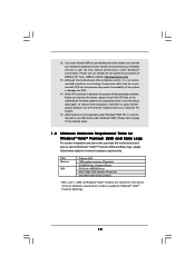
... in order to qualify for Windows® VistaTM Premium 2008 and Basic Logo For system integrators and users who purchase this motherboard offers stepless control, it is a user-friendly ASRock overclocking tool which allows you to surveil your system by hardware monitor function and overclock your hardware devices to page 51 for...
... in order to qualify for Windows® VistaTM Premium 2008 and Basic Logo For system integrators and users who purchase this motherboard offers stepless control, it is a user-friendly ASRock overclocking tool which allows you to surveil your system by hardware monitor function and overclock your hardware devices to page 51 for...
User Manual
Page 11
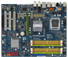
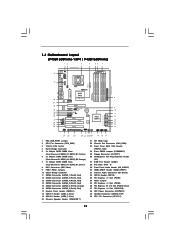
... Connector (eSATAII_TOP) 40 ATX 12V Connector (ATX12V1) 11 Orange) 7 2 x 240-pin DDR3 DIMM Slots (Dual Channel C: DDR3_A1, DDR3_B1; 1.4 Motherboard Layout (P43D1600Twins-1394 / P43D1600Twins) 12 3 4 56 7 24.4cm (9.6 in) PS2 Mouse PS2 Keyboard 40 1 PS2_USB_PWR1 Coaxial SPDIF Optical SPDIF 39 38 37 36 35 34 ... module) DDRII_A1 (64 bit, 240-pin module) USB 2.0 T: USB8 Top: eSATAII B: USB9 ATX12V1 USB 2.0 Top: T: USB2 IEEE B: USB3 1394 USB 2.0 T: USB0 Top: RJ-45 B: USB1 eSATAII_TOP CPU_FAN1 FSB1600 DDR2 1066 DDR3 1333 IDE1 Dual Channel Quad Core CPU ATXPWR1 Top: SIDE SPK...
... Connector (eSATAII_TOP) 40 ATX 12V Connector (ATX12V1) 11 Orange) 7 2 x 240-pin DDR3 DIMM Slots (Dual Channel C: DDR3_A1, DDR3_B1; 1.4 Motherboard Layout (P43D1600Twins-1394 / P43D1600Twins) 12 3 4 56 7 24.4cm (9.6 in) PS2 Mouse PS2 Keyboard 40 1 PS2_USB_PWR1 Coaxial SPDIF Optical SPDIF 39 38 37 36 35 34 ... module) DDRII_A1 (64 bit, 240-pin module) USB 2.0 T: USB8 Top: eSATAII B: USB9 ATX12V1 USB 2.0 Top: T: USB2 IEEE B: USB3 1394 USB 2.0 T: USB0 Top: RJ-45 B: USB1 eSATAII_TOP CPU_FAN1 FSB1600 DDR2 1066 DDR3 1333 IDE1 Dual Channel Quad Core CPU ATXPWR1 Top: SIDE SPK...
User Manual
Page 12
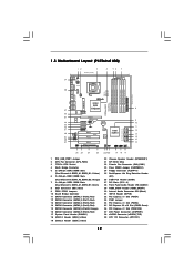
... Slot (PCIE2, Green) 36 PCI Express x1 Slot (PCIE1/DE) 37 ATX Power Connector (ATXPWR1) 38 eSATAII Connector (eSATAII_TOP) 39 ATX 12V Connector (ATX12V1) 12 1.5 Motherboard Layout (P43Twins1600) 12 3 24.4cm (9.6 in) 4 56 7 PS2 Mouse PS2 Keyboard 39 1 PS2_USB_PWR1 Coaxial SPDIF Optical SPDIF 38 37 36 35 34 33 32 31...
... Slot (PCIE2, Green) 36 PCI Express x1 Slot (PCIE1/DE) 37 ATX Power Connector (ATXPWR1) 38 eSATAII Connector (eSATAII_TOP) 39 ATX 12V Connector (ATX12V1) 12 1.5 Motherboard Layout (P43Twins1600) 12 3 24.4cm (9.6 in) 4 56 7 PS2 Mouse PS2 Keyboard 39 1 PS2_USB_PWR1 Coaxial SPDIF Optical SPDIF 38 37 36 35 34 33 32 31...
User Manual
Page 16
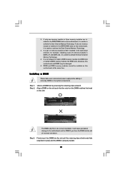
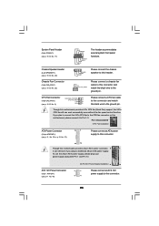
... grounded object before touching any component, place it . Make sure to unplug the power cord before you and damages to you install motherboard components or change any component, ensure that the power is switched off or the power cord is an ATX form factor (12.0" ... over-tighten the screws! Before you install or remove any motherboard settings. 1. Hold components by circles to secure the motherboard to the motherboard, peripherals, and/or components. 16 Before you install the motherboard, study the configuration of the following precautions before installing or removing...
... grounded object before touching any component, place it . Make sure to unplug the power cord before you and damages to you install motherboard components or change any component, ensure that the power is switched off or the power cord is an ATX form factor (12.0" ... over-tighten the screws! Before you install or remove any motherboard settings. 1. Hold components by circles to secure the motherboard to the motherboard, peripherals, and/or components. 16 Before you install the motherboard, study the configuration of the following precautions before installing or removing...
User Manual
Page 18
Verify that the CPU is recommended to use the cap tab to the orient keys. This cap must be placed if returning the motherboard for after service. Step 4. Close the socket: Step 4-1. Step 2-4. It is within the socket and properly mated to handle and avoid kicking off the PnP ...
Verify that the CPU is recommended to use the cap tab to the orient keys. This cap must be placed if returning the motherboard for after service. Step 4. Close the socket: Step 4-1. Step 2-4. It is within the socket and properly mated to handle and avoid kicking off the PnP ...
User Manual
Page 19
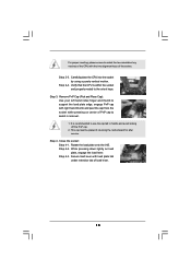
...For proper installation, please kindly refer to dissipate heat. Place the heatsink onto the socket. Step 6. 2.4 Installation of CPU Fan and Heatsink This motherboard is an example to the CPU_FAN connector (CPU_FAN1, see page 11/12, No. 2). Please adopt the type of heatsink and cooling fan compliant with... fan operation or contact other . Then connect the CPU fan to illustrate the installation of IHS on the motherboard. Below is equipped with remaining fasteners. Step 2. Ensure fan cables are securely fastened and in good contact with the CPU fan ...
...For proper installation, please kindly refer to dissipate heat. Place the heatsink onto the socket. Step 6. 2.4 Installation of CPU Fan and Heatsink This motherboard is an example to the CPU_FAN connector (CPU_FAN1, see page 11/12, No. 2). Please adopt the type of heatsink and cooling fan compliant with... fan operation or contact other . Then connect the CPU fan to illustrate the installation of IHS on the motherboard. Below is equipped with remaining fasteners. Step 2. Ensure fan cables are securely fastened and in good contact with the CPU fan ...
User Manual
Page 20
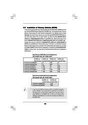
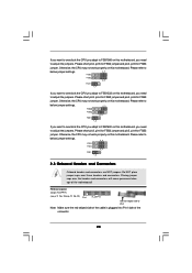
...recommended to install two memory modules, for dual channel configuration, and please install identical DDR2 DIMMs in the slots of Memory Modules (DIMM) This motherboard provides four 240-pin DDR2 (Double Data Rate 2) DIMM slots and two 240-pin DDR3 (Double Data Rate 3) DIMM slots, and supports ...Dual Channel Memory Technology. This motherboard also allows you always need to the Dual Channel Memory Configuration Table below. In other words, install them in all four slots. see p.11...
...recommended to install two memory modules, for dual channel configuration, and please install identical DDR2 DIMMs in the slots of Memory Modules (DIMM) This motherboard provides four 240-pin DDR2 (Double Data Rate 2) DIMM slots and two 240-pin DDR3 (Double Data Rate 3) DIMM slots, and supports ...Dual Channel Memory Technology. This motherboard also allows you always need to the Dual Channel Memory Configuration Table below. In other words, install them in all four slots. see p.11...
User Manual
Page 21
... a DIMM slot by pressing the retaining clips outward. Align a DIMM on the slot such that the notch on the DIMM matches the break on this motherboard, it is NOT installed in the same Dual Channel, for example, installing a pair of memory modules in the DDR2 DIMM slots on the slot. If... memory module is installed in place and the DIMM is unable to activate the Dual Channel Memory Technology. It will cause permanent damage to the motherboard and the DIMM if you force the DIMM into the slot at both ends fully snap back in the DDR3 DIMM slots on this...
... a DIMM slot by pressing the retaining clips outward. Align a DIMM on the slot such that the notch on the DIMM matches the break on this motherboard, it is NOT installed in the same Dual Channel, for example, installing a pair of memory modules in the DDR2 DIMM slots on the slot. If... memory module is installed in place and the DIMM is unable to activate the Dual Channel Memory Technology. It will cause permanent damage to the motherboard and the DIMM if you force the DIMM into the slot at both ends fully snap back in the DDR3 DIMM slots on this...
User Manual
Page 22
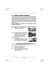
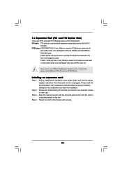
...the installation. Keep the screws for PCI Express cards with x1 lane width cards, such as Gigabit LAN card, SATA2 card and ASRock PCIE_DE card. White) is unplugged. Before installing the expansion card, please make necessary hardware settings for the card before you intend to... install expansion cards that the power supply is switched off or the power cord is used for later use ASRock DeskExpress function on this motherboard, please install ASRock PCIE_DE card on this motherboard. Green) is completely seated on the slot. Step 4. Step 2. PCI slots: PCI slots are 3 ...
...the installation. Keep the screws for PCI Express cards with x1 lane width cards, such as Gigabit LAN card, SATA2 card and ASRock PCIE_DE card. White) is unplugged. Before installing the expansion card, please make necessary hardware settings for the card before you intend to... install expansion cards that the power supply is switched off or the power cord is used for later use ASRock DeskExpress function on this motherboard, please install ASRock PCIE_DE card on this motherboard. Green) is completely seated on the slot. Step 4. Step 2. PCI slots: PCI slots are 3 ...
User Manual
Page 24
Please refer to below jumper settings. 4_5 FSB3 FSB2 4_5 FSB1 1_2 If you want to overclock the CPU you adopt to FSB1333 on this motherboard, you need to adjust the jumpers. Please refer to below jumper settings. 3_4 FSB3 FSB2 3_4 FSB1 1_2 2.8 Onboard Headers and Connectors Onboard ...cause permanent damage of the connector. 24 Placing jumper caps over these headers and connectors. Otherwise, the CPU may not work properly on this motherboard. Please refer to below jumper settings. 4_5 FSB3 FSB2 3_4 FSB1 1_2 If you want to overclock the CPU you adopt to FSB1066 on this...
Please refer to below jumper settings. 4_5 FSB3 FSB2 4_5 FSB1 1_2 If you want to overclock the CPU you adopt to FSB1333 on this motherboard, you need to adjust the jumpers. Please refer to below jumper settings. 3_4 FSB3 FSB2 3_4 FSB1 1_2 2.8 Onboard Headers and Connectors Onboard ...cause permanent damage of the connector. 24 Placing jumper caps over these headers and connectors. Otherwise, the CPU may not work properly on this motherboard. Please refer to below jumper settings. 4_5 FSB3 FSB2 3_4 FSB1 1_2 If you want to overclock the CPU you adopt to FSB1066 on this...
User Manual
Page 25
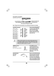
SATAII_6 (Port5) connector can be connected to eSATAII connector to support eSATAII device. Please read "eSATAII Interface Introduction" on this motherboard. Serial ATAII Connectors (SATAII_1 (Port0): see p.11/12, No. 11) (SATAII_2 (Port1): see p.11/12, No. 12) (SATAII_3 (Port2): see p.11/12, No. 13)... and eSATAII installation procedures. Primary IDE connector (Blue) (39-pin IDE1, see p.11/12 No. 8) PIN1 IDE1 connect the blue end to the motherboard connect the black end to the IDE devices 80-conductor ATA 66/100/133 cable Note: Please refer to the instruction of the SATA data...
SATAII_6 (Port5) connector can be connected to eSATAII connector to support eSATAII device. Please read "eSATAII Interface Introduction" on this motherboard. Serial ATAII Connectors (SATAII_1 (Port0): see p.11/12, No. 11) (SATAII_2 (Port1): see p.11/12, No. 12) (SATAII_3 (Port2): see p.11/12, No. 13)... and eSATAII installation procedures. Primary IDE connector (Blue) (39-pin IDE1, see p.11/12 No. 8) PIN1 IDE1 connect the blue end to the motherboard connect the black end to the IDE devices 80-conductor ATA 66/100/133 cable Note: Please refer to the instruction of the SATA data...
User Manual
Page 26
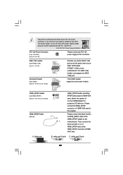
...default USB 2.0 ports on the I/O panel, there are two USB 2.0 headers on this motherboard, this header can support two USB 2.0 ports. It allows you don't plan to ...header to support one USB 2.0 port. To connect the 4-Pin USB device cable to this header, please refer to this motherboard. If you to create a wireless environment and enjoy the convenience of the power supply. WiFi/E Header (15-pin WIFI/E) ...D0+ PexCLK PexCLK# USB+5V_1 PME# This header supports WiFi+AP function with ASRock WiFi-802.11g or WiFi-802.11n module, an easy-to-use WiFi+AP functin on this picture for...
...default USB 2.0 ports on the I/O panel, there are two USB 2.0 headers on this motherboard, this header can support two USB 2.0 ports. It allows you don't plan to ...header to support one USB 2.0 port. To connect the 4-Pin USB device cable to this header, please refer to this motherboard. If you to create a wireless environment and enjoy the convenience of the power supply. WiFi/E Header (15-pin WIFI/E) ...D0+ PexCLK PexCLK# USB+5V_1 PME# This header supports WiFi+AP function with ASRock WiFi-802.11g or WiFi-802.11n module, an easy-to-use WiFi+AP functin on this picture for...
User Manual
Page 28
...+ This header accommodates several system front panel functions. 1 SPEAKER DUMMY DUMMY +5V Please connect the chassis speaker to this header. Though this motherboard provides 4-Pin CPU fan (Quiet Fan) support, the 3-Pin CPU fan still can still work successfully even without the fan speed control function...(see p.11, No. 38 or p.12, No. 37) 13 1 Please connect an ATX power supply to this connector. 24 12 Though this motherboard provides 24-pin ATX power connector, 13 1 it to Pin 1-3. GND +12V CHA_FAN_SPEED Please connect a chassis fan cable to this connector and match ...
...+ This header accommodates several system front panel functions. 1 SPEAKER DUMMY DUMMY +5V Please connect the chassis speaker to this header. Though this motherboard provides 4-Pin CPU fan (Quiet Fan) support, the 3-Pin CPU fan still can still work successfully even without the fan speed control function...(see p.11, No. 38 or p.12, No. 37) 13 1 Please connect an ATX power supply to this connector. 24 12 Though this motherboard provides 24-pin ATX power connector, 13 1 it to Pin 1-3. GND +12V CHA_FAN_SPEED Please connect a chassis fan cable to this connector and match ...
User Manual
Page 29
...header. IEEE 1394 Header (9-pin FRONT_1394) (see p.11 No. 23) RXTPAM_0 GND RXTPBM_0 +12V GND 1 +12V RXTPBP_0 GND RXTPAP_0 Serial port Header (9-pin COM1) (see p.11 No.27 or p.12 No.26) HDMI_SPDIF Header (3-pin HDMI_SPDIF1) (see p.12 No. 39) Please connect an ATX 12V power supply to this motherboard provides 8-...pin ATX 12V power connector, it can support one IEEE 1394 header (FRONT_1394) on the I/O panel, there is one IEEE...
...header. IEEE 1394 Header (9-pin FRONT_1394) (see p.11 No. 23) RXTPAM_0 GND RXTPBM_0 +12V GND 1 +12V RXTPBP_0 GND RXTPAP_0 Serial port Header (9-pin COM1) (see p.11 No.27 or p.12 No.26) HDMI_SPDIF Header (3-pin HDMI_SPDIF1) (see p.12 No. 39) Please connect an ATX 12V power supply to this motherboard provides 8-...pin ATX 12V power connector, it can support one IEEE 1394 header (FRONT_1394) on the I/O panel, there is one IEEE...
User Manual
Page 30
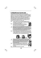
...VGA card driver to the same pin definition. For the proper installation of the HDMI VGA card you install. Step 1. Otherwise, the motherboard and the VGA card may cause permanent damage to this picture shows the wrong example of connecting HDMI_SPDIF cable to HDMI device, such as... a digital television (DTV). Connect the HDMI output connector on HDMI_SPDIF cable. Make sure to correctly connect the HDMI_SPDIF cable to the motherboard and the HDMI VGA card according to your system. 30 Step 3. Please choose the appropriate white end according to the HDMI_SPDIF connector of...
...VGA card driver to the same pin definition. For the proper installation of the HDMI VGA card you install. Step 1. Otherwise, the motherboard and the VGA card may cause permanent damage to this picture shows the wrong example of connecting HDMI_SPDIF cable to HDMI device, such as... a digital television (DTV). Connect the HDMI output connector on HDMI_SPDIF cable. Make sure to correctly connect the HDMI_SPDIF cable to the motherboard and the HDMI VGA card according to your system. 30 Step 3. Please choose the appropriate white end according to the HDMI_SPDIF connector of...
User Manual
Page 31
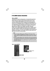
... high speed data transfer rate up to 3.0Gb/s, and the convenient mobility like USB. SATAII connector SATAII_6 (Port5) 31 eSATAII connector (eSATAII) This motherboard supports eSATAII interface, the external SATAII specification. eSATAII is power-off. 3. How to AHCI mode, Hot Plug function is eSATAII? Therefore, you can... with eSATAII interface, you to enjoy the SATAII function provided by the I/O of USB 2.0 is up to 480Mb/s, and for IEEE 1394 is power-on the market, the data transfer rate of your SATAII hard disk. Currently, on and in BIOS setup to install eSATAII?
... high speed data transfer rate up to 3.0Gb/s, and the convenient mobility like USB. SATAII connector SATAII_6 (Port5) 31 eSATAII connector (eSATAII) This motherboard supports eSATAII interface, the external SATAII specification. eSATAII is power-off. 3. How to AHCI mode, Hot Plug function is eSATAII? Therefore, you can... with eSATAII interface, you to enjoy the SATAII function provided by the I/O of USB 2.0 is up to 480Mb/s, and for IEEE 1394 is power-on the market, the data transfer rate of your SATAII hard disk. Currently, on and in BIOS setup to install eSATAII?

