
User Manual
Page 6
... Windows® VistaTM Premium Level HD Audio (ALC888 Audio Codec) - All Solid Capacitor design (For P43D1600Twins-1394 / P43D1600Twins Only) - Max. capacity of system memory: 16GB (see CAUTION 6) - 4 x DDR2 DIMM ...Port - 1 x Optical SPDIF Out Port - 6 x Ready-to-Use USB 2.0 Ports - 1 x eSATAII Port - 1 x RJ-45 LAN Port with LED (ACT/LINK LED and SPEED LED) 6 Realtek RTL8111B/RTL8111C - Support DDR3 1333/1066 non-ECC, un-buffered memory (see CAUTION 1) - ATX Form Factor: 12.0-in x 9.6-in, 30.5 cm x 24.4 cm - Supports EM64T CPU - Supports Wake-On-LAN P43D1600Twins-1394 ASRock...
... Windows® VistaTM Premium Level HD Audio (ALC888 Audio Codec) - All Solid Capacitor design (For P43D1600Twins-1394 / P43D1600Twins Only) - Max. capacity of system memory: 16GB (see CAUTION 6) - 4 x DDR2 DIMM ...Port - 1 x Optical SPDIF Out Port - 6 x Ready-to-Use USB 2.0 Ports - 1 x eSATAII Port - 1 x RJ-45 LAN Port with LED (ACT/LINK LED and SPEED LED) 6 Realtek RTL8111B/RTL8111C - Support DDR3 1333/1066 non-ECC, un-buffered memory (see CAUTION 1) - ATX Form Factor: 12.0-in x 9.6-in, 30.5 cm x 24.4 cm - Supports EM64T CPU - Supports Wake-On-LAN P43D1600Twins-1394 ASRock...

User Manual
Page 7
... ASRock SPDIF I/O - 1 x PS/2 Mouse Port - 1 x PS/2 Keyboard Port - 1 x Coaxial SPDIF Out Port - 1 x Optical SPDIF Out Port - 6 x Ready-to-Use USB 2.0 Ports - 1 x eSATAII Port - 1 x RJ-45 LAN Port with LED (ACT/LINK LED and SPEED LED) (P43D1600Twins) - 1 x RJ-45 LAN Port (P43Twins1600) - Front panel audio connector - 2 x USB 2.0 headers (support 4 USB 2.0 ports) (see CAUTION 10) - 1 x WiFi/E header (see CAUTION 11) - 8Mb AMI BIOS (P43D1600Twins-1394 / P43D1600Twins...
... ASRock SPDIF I/O - 1 x PS/2 Mouse Port - 1 x PS/2 Keyboard Port - 1 x Coaxial SPDIF Out Port - 1 x Optical SPDIF Out Port - 6 x Ready-to-Use USB 2.0 Ports - 1 x eSATAII Port - 1 x RJ-45 LAN Port with LED (ACT/LINK LED and SPEED LED) (P43D1600Twins) - 1 x RJ-45 LAN Port (P43Twins1600) - Front panel audio connector - 2 x USB 2.0 headers (support 4 USB 2.0 ports) (see CAUTION 10) - 1 x WiFi/E header (see CAUTION 11) - 8Mb AMI BIOS (P43D1600Twins-1394 / P43D1600Twins...
User Manual
Page 11
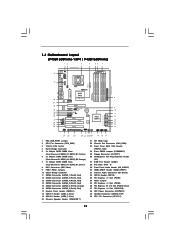
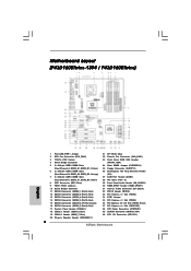
...21 SPI BIOS Chip 22 Chassis Fan Connector (CHA_FAN1) 23 Front Panel IEEE 1394 Header (FRONT_1394) 24 Clear CMOS Jumper (CLRCMOS1) 25 Floppy Connector (FLOPPY1) 26 DeskExpress Hot Plug Detection Header (IR1) 27 COM Port Header (COM1) 28 PCI Slots (PCI1 - 3) 29 Front Panel Audio Header...Express x1 Slot (PCIE1/DE) 38 ATX Power Connector (ATXPWR1) 39 eSATAII Connector (eSATAII_TOP) 40 ATX 12V Connector (ATX12V1) 11 1.4 Motherboard Layout (P43D1600Twins-1394 / P43D1600Twins) 12 3 4 56 7 24.4cm (9.6 in) PS2 Mouse PS2 Keyboard 40 1 PS2_USB_PWR1 Coaxial SPDIF Optical SPDIF 39 38 37 36 35 34...
...21 SPI BIOS Chip 22 Chassis Fan Connector (CHA_FAN1) 23 Front Panel IEEE 1394 Header (FRONT_1394) 24 Clear CMOS Jumper (CLRCMOS1) 25 Floppy Connector (FLOPPY1) 26 DeskExpress Hot Plug Detection Header (IR1) 27 COM Port Header (COM1) 28 PCI Slots (PCI1 - 3) 29 Front Panel Audio Header...Express x1 Slot (PCIE1/DE) 38 ATX Power Connector (ATXPWR1) 39 eSATAII Connector (eSATAII_TOP) 40 ATX 12V Connector (ATX12V1) 11 1.4 Motherboard Layout (P43D1600Twins-1394 / P43D1600Twins) 12 3 4 56 7 24.4cm (9.6 in) PS2 Mouse PS2 Keyboard 40 1 PS2_USB_PWR1 Coaxial SPDIF Optical SPDIF 39 38 37 36 35 34...
User Manual
Page 12
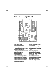
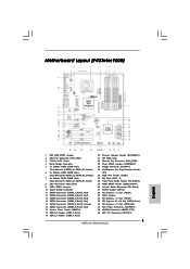
... BIOS Chip 22 Chassis Fan Connector (CHA_FAN1) 23 Clear CMOS Jumper (CLRCMOS1) 24 Floppy Connector (FLOPPY1) 25 DeskExpress Hot Plug Detection Header (IR1) 26 COM Port Header (COM1) 27 PCI Slots (PCI1 - 3) 28 Front Panel Audio Header (HD_AUDIO1) 29 HDMI_SPDIF Header (HDMI_SPDIF1) 30 Internal Audio Connector: CD1 (Black) 31 WiFi/E Header...
... BIOS Chip 22 Chassis Fan Connector (CHA_FAN1) 23 Clear CMOS Jumper (CLRCMOS1) 24 Floppy Connector (FLOPPY1) 25 DeskExpress Hot Plug Detection Header (IR1) 26 COM Port Header (COM1) 27 PCI Slots (PCI1 - 3) 28 Front Panel Audio Header (HD_AUDIO1) 29 HDMI_SPDIF Header (HDMI_SPDIF1) 30 Internal Audio Connector: CD1 (Black) 31 WiFi/E Header...
User Manual
Page 13
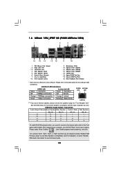
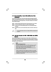
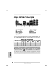
Choose "2CH", "4CH", "6CH", or "8CH" and then you are two LED next to the LAN port. 1 . 6 ASRock 1394_SPDIF I/O (P43D1600Twins-1394) 1 2 3 4 7 5 8 6 9 16 15 14 13 12 11 10 1 PS/2 Mouse Port (Green) 2 IEEE 1394 Port * 3 LAN RJ-45 Port 4 Side Speaker (Gray) 5 Rear Speaker (Black) 6 Central / Bass (Orange) 7 Line In (Light Blue) **8 Front Speaker (Lime) 9 Microphone (Pink) 10 USB...
Choose "2CH", "4CH", "6CH", or "8CH" and then you are two LED next to the LAN port. 1 . 6 ASRock 1394_SPDIF I/O (P43D1600Twins-1394) 1 2 3 4 7 5 8 6 9 16 15 14 13 12 11 10 1 PS/2 Mouse Port (Green) 2 IEEE 1394 Port * 3 LAN RJ-45 Port 4 Side Speaker (Gray) 5 Rear Speaker (Black) 6 Central / Bass (Orange) 7 Line In (Light Blue) **8 Front Speaker (Lime) 9 Microphone (Pink) 10 USB...

User Manual
Page 14
... will find "Mixer" tool on your system. After restarting your computer, you are two LED next to the LAN port. 1 . 7 ASRock SPDIF I/O (P43D1600Twins) 1 2 3 6 4 7 5 8 15 14 13 12 11 10 9 1 PS/2 Mouse Port (Green) * 2 LAN RJ-45 Port 3 Side Speaker (Gray) 4 Rear Speaker (Black) 5 Central / Bass (Orange) 6 Line In (Light Blue) **7 Front Speaker (Lime) 8 Microphone (Pink...
... will find "Mixer" tool on your system. After restarting your computer, you are two LED next to the LAN port. 1 . 7 ASRock SPDIF I/O (P43D1600Twins) 1 2 3 6 4 7 5 8 15 14 13 12 11 10 9 1 PS/2 Mouse Port (Green) * 2 LAN RJ-45 Port 3 Side Speaker (Gray) 4 Rear Speaker (Black) 5 Central / Bass (Orange) 6 Line In (Light Blue) **7 Front Speaker (Lime) 8 Microphone (Pink...
User Manual
Page 15
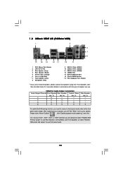
...with the type of speaker you need to connect a front panel audio cable to use . 1 . 8 ASRock SPDIF I/O (P43Twins1600) 1 2 3 6 4 7 5 8 15 14 13 12 11 10 9 1 PS/2 Mouse Port (Green) 2 LAN RJ-45 Port 3 Side Speaker (Gray) 4 Rear Speaker (Black) 5 Central / Bass (Orange) 6 Line In (Light... Blue) * 7 Front Speaker (Lime) 8 Microphone (Pink) 9 USB 2.0 Ports (USB01) 10 USB 2.0 Ports (USB23) 11 USB 2.0 Ports (USB89) 12 eSATAII Port 13 Optical SPDIF Out Port 14 Coaxial SPDIF Out Port 15 PS/2 Keyboard Port (Purple) * If you will find "Mixer" tool on your system. See the ...
...with the type of speaker you need to connect a front panel audio cable to use . 1 . 8 ASRock SPDIF I/O (P43Twins1600) 1 2 3 6 4 7 5 8 15 14 13 12 11 10 9 1 PS/2 Mouse Port (Green) 2 LAN RJ-45 Port 3 Side Speaker (Gray) 4 Rear Speaker (Black) 5 Central / Bass (Orange) 6 Line In (Light... Blue) * 7 Front Speaker (Lime) 8 Microphone (Pink) 9 USB 2.0 Ports (USB01) 10 USB 2.0 Ports (USB23) 11 USB 2.0 Ports (USB89) 12 eSATAII Port 13 Optical SPDIF Out Port 14 Coaxial SPDIF Out Port 15 PS/2 Keyboard Port (Purple) * If you will find "Mixer" tool on your system. See the ...
User Manual
Page 26
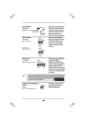
... function for proper installation. It allows you don't plan to -use WiFi+AP functin on this header can support two USB 2.0 ports. If you to this header, please refer to create a wireless environment and enjoy the convenience of wireless network connectivity. To connect the... 4-Pin USB device cable to this picture for ASRock DeskExpress. 26 Serial ATA (SATA) Power Cable (Optional) connect to the SATA HDD power connector connect to the power supply USB 2.0 Headers...
... function for proper installation. It allows you don't plan to -use WiFi+AP functin on this header can support two USB 2.0 ports. If you to this header, please refer to create a wireless environment and enjoy the convenience of wireless network connectivity. To connect the... 4-Pin USB device cable to this picture for ASRock DeskExpress. 26 Serial ATA (SATA) Power Cable (Optional) connect to the SATA HDD power connector connect to the power supply USB 2.0 Headers...
User Manual
Page 29
...+5V SPDIFOUT GND blue black SPDIFOUT GND blue black SPDIFOUT GND blue black 29 IEEE 1394 Header (9-pin FRONT_1394) (see p.11 No. 23) RXTPAM_0 GND RXTPBM_0 +12V GND 1 +12V RXTPBP_0 GND RXTPAP_0 Serial port Header (9-pin COM1) (see p.11 No.27 or p.12 No.26) HDMI_SPDIF ... 1 RRI#1 RRTS#1 GND TTXD1 DDCD#1 1 GND SPDIFOUT +5V HDMI_SPDIF Cable (Optional) C B A Besides one default IEEE 1394 port on the I/O panel, there is one IEEE 1394 port. Please connect the HDMI_SPDIF connector of HDMI VGA card to connect HDMI Digital TV/ projector/LCD devices. Though this motherboard provides 8-pin...
...+5V SPDIFOUT GND blue black SPDIFOUT GND blue black SPDIFOUT GND blue black 29 IEEE 1394 Header (9-pin FRONT_1394) (see p.11 No. 23) RXTPAM_0 GND RXTPBM_0 +12V GND 1 +12V RXTPBP_0 GND RXTPAP_0 Serial port Header (9-pin COM1) (see p.11 No.27 or p.12 No.26) HDMI_SPDIF ... 1 RRI#1 RRTS#1 GND TTXD1 DDCD#1 1 GND SPDIFOUT +5V HDMI_SPDIF Cable (Optional) C B A Besides one default IEEE 1394 port on the I/O panel, there is one IEEE 1394 port. Please connect the HDMI_SPDIF connector of HDMI VGA card to connect HDMI Digital TV/ projector/LCD devices. Though this motherboard provides 8-pin...
User Manual
Page 31
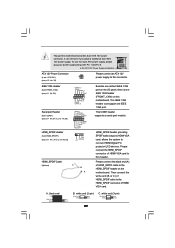
...interface. SATAII connector SATAII_6 (Port5) 31 eSATAII connector (eSATAII) If you to install eSATAII? Please refer to page 39 to the eSATAII ports only when the system is not supported with Hot Plug capability that enables you still want to use eSATAII function in working condition. 2. ...Currently, on the basis of opening your computer, offering the high speed data transfer rate up to the eSATAII ports while the system is much higher than USB 2.0 and IEEE 1394, and still keeps the convenience of your chassis to IDE mode, Hot Plug function is power-off. 3. Therefore...
...interface. SATAII connector SATAII_6 (Port5) 31 eSATAII connector (eSATAII) If you to install eSATAII? Please refer to page 39 to the eSATAII ports only when the system is not supported with Hot Plug capability that enables you still want to use eSATAII function in working condition. 2. ...Currently, on the basis of opening your computer, offering the high speed data transfer rate up to the eSATAII ports while the system is much higher than USB 2.0 and IEEE 1394, and still keeps the convenience of your chassis to IDE mode, Hot Plug function is power-off. 3. Therefore...

User Manual
Page 32
... I /O shield. Connect one end of the eSATAII device cable to eSATAII device Connect the other end of the eSATAII device cable to enable the eSATAII port of the I/O shield 32 see p.11 No.39 or p.12 No.38) with a SATA data cable first. see p.11/12 No.15) and the eSATAII...)) Connect the SATA data cable to connect the orange SATAII connector (SATAII_6 (Port5); 1. Use the eSATAII device cable to connect eSATAII device and the eSATAII port of the I /O shield, you need to the eSATAII connector (eSATAII_TOP) 2.
... I /O shield. Connect one end of the eSATAII device cable to eSATAII device Connect the other end of the eSATAII device cable to enable the eSATAII port of the I/O shield 32 see p.11 No.39 or p.12 No.38) with a SATA data cable first. see p.11/12 No.15) and the eSATAII...)) Connect the SATA data cable to connect the orange SATAII connector (SATAII_6 (Port5); 1. Use the eSATAII device cable to connect eSATAII device and the eSATAII port of the I /O shield, you need to the eSATAII connector (eSATAII_TOP) 2.
User Manual
Page 35
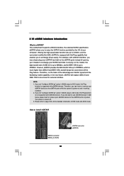
... note that it is called "Hot Plug" for SATA / SATAII / eSATAII Devices in working condition. You may simply plug your eSATAII devices to the eSATAII ports instead of your chassis to exchange drives easily. This section will guide you to the motherboard's SATAII connector. STEP 3: Connect one end of the SATA...
... note that it is called "Hot Plug" for SATA / SATAII / eSATAII Devices in working condition. You may simply plug your eSATAII devices to the eSATAII ports instead of your chassis to exchange drives easily. This section will guide you to the motherboard's SATAII connector. STEP 3: Connect one end of the SATA...

User Manual
Page 55
...2F8 / IRQ3], [3E8 / IRQ4], [2E8 / IRQ3]. Infrared Port Address Use this section, you plan to use ASRock DeskExpress on [Disabled] option. 55 3.3.6 Floppy Configuration In this item to set the address for the onboard infrared port or disable it . If you may configure the type of floppy...BIOS SETUP UTILITY Advanced Configure Super IO Chipset OnBoard Floppy Controller Serial Port Address Infrared Port Address [Enabled] [3F8 / IRQ4] [Disabled] Allow BIOS to enable or disable floppy drive controller. Serial Port Address Use this item on this motherboard, please keep this item to...
...2F8 / IRQ3], [3E8 / IRQ4], [2E8 / IRQ3]. Infrared Port Address Use this section, you plan to use ASRock DeskExpress on [Disabled] option. 55 3.3.6 Floppy Configuration In this item to set the address for the onboard infrared port or disable it . If you may configure the type of floppy...BIOS SETUP UTILITY Advanced Configure Super IO Chipset OnBoard Floppy Controller Serial Port Address Infrared Port Address [Enabled] [3F8 / IRQ4] [Disabled] Allow BIOS to enable or disable floppy drive controller. Serial Port Address Use this item on this motherboard, please keep this item to...
Quick Installation Guide
Page 2
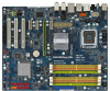
Motherboard Layout (P43D1600Twins-1394 / P43D1600Twins) English 1 PS2_USB_PWR1 Jumper 2 CPU Fan Connector (CPU_FAN1) 3 775-Pin CPU Socket 4 North Bridge Controller 5 2 x ...22 Chassis Fan Connector (CHA_FAN1) 23 Front Panel IEEE 1394 Header (FRONT_1394) 24 Clear CMOS Jumper (CLRCMOS1) 25 Floppy Connector (FLOPPY1) 26 DeskExpress Hot Plug Detection Header (IR1) 27 COM Port Header (COM1) 28 PCI Slots (PCI1 - 3) 29... Connector (ATXPWR1) 39 eSATAII Connector (eSATAII_TOP) 40 ATX 12V Connector (ATX12V1) 2 ASRock Motherboard Yellow) 6 2 x 240-pin DDR2 DIMM Slots (Dual Channel B: DDRII_A2, DDRII_B2;
Motherboard Layout (P43D1600Twins-1394 / P43D1600Twins) English 1 PS2_USB_PWR1 Jumper 2 CPU Fan Connector (CPU_FAN1) 3 775-Pin CPU Socket 4 North Bridge Controller 5 2 x ...22 Chassis Fan Connector (CHA_FAN1) 23 Front Panel IEEE 1394 Header (FRONT_1394) 24 Clear CMOS Jumper (CLRCMOS1) 25 Floppy Connector (FLOPPY1) 26 DeskExpress Hot Plug Detection Header (IR1) 27 COM Port Header (COM1) 28 PCI Slots (PCI1 - 3) 29... Connector (ATXPWR1) 39 eSATAII Connector (eSATAII_TOP) 40 ATX 12V Connector (ATX12V1) 2 ASRock Motherboard Yellow) 6 2 x 240-pin DDR2 DIMM Slots (Dual Channel B: DDRII_A2, DDRII_B2;
Quick Installation Guide
Page 3
... BIOS Chip 22 Chassis Fan Connector (CHA_FAN1) 23 Clear CMOS Jumper (CLRCMOS1) 24 Floppy Connector (FLOPPY1) 25 DeskExpress Hot Plug Detection Header (IR1) 26 COM Port Header (COM1) 27 PCI Slots (PCI1 - 3) 28 Front Panel Audio Header (HD_AUDIO1) 29 HDMI_SPDIF Header (HDMI_SPDIF1) 30 Internal Audio Connector: CD1 (Black) 31 WiFi/E Header... 2.0 x16 Slot (PCIE2, Green) 36 PCI Express x1 Slot (PCIE1/DE) 37 ATX Power Connector (ATXPWR1) 38 eSATAII Connector (eSATAII_TOP) 39 ATX 12V Connector (ATX12V1) 3 ASRock Motherboard
... BIOS Chip 22 Chassis Fan Connector (CHA_FAN1) 23 Clear CMOS Jumper (CLRCMOS1) 24 Floppy Connector (FLOPPY1) 25 DeskExpress Hot Plug Detection Header (IR1) 26 COM Port Header (COM1) 27 PCI Slots (PCI1 - 3) 28 Front Panel Audio Header (HD_AUDIO1) 29 HDMI_SPDIF Header (HDMI_SPDIF1) 30 Internal Audio Connector: CD1 (Black) 31 WiFi/E Header... 2.0 x16 Slot (PCIE2, Green) 36 PCI Express x1 Slot (PCIE1/DE) 37 ATX Power Connector (ATXPWR1) 38 eSATAII Connector (eSATAII_TOP) 39 ATX 12V Connector (ATX12V1) 3 ASRock Motherboard
Quick Installation Guide
Page 4
...". After restarting your computer, you use 2-channel speaker, please connect the speaker's plug into "Front Speaker Jack". Please refer to the LAN port. ASRock 1394_SPDIF I/O (P43D1600Twins-1394) 1 PS/2 Mouse Port (Green) 2 IEEE 1394 Port * 3 LAN RJ-45 Port 4 Side Speaker (Gray) 5 Rear Speaker (Black) 6 Central / Bass (Orange) 7 Line In (Light Blue) **8 Front Speaker (Lime) 9 Microphone (Pink) 10 USB...
...". After restarting your computer, you use 2-channel speaker, please connect the speaker's plug into "Front Speaker Jack". Please refer to the LAN port. ASRock 1394_SPDIF I/O (P43D1600Twins-1394) 1 PS/2 Mouse Port (Green) 2 IEEE 1394 Port * 3 LAN RJ-45 Port 4 Side Speaker (Gray) 5 Rear Speaker (Black) 6 Central / Bass (Orange) 7 Line In (Light Blue) **8 Front Speaker (Lime) 9 Microphone (Pink) 10 USB...

Quick Installation Guide
Page 5
... need to connect a front panel audio cable to use front panel audio. 5 ASRock Motherboard English Please select "Mixer ToolBox" , click "Enable playback multi-streaming", and click "ok". ASRock SPDIF I/O (P43D1600Twins) PEED ACT/LINK LED LED LAN Port 1 PS/2 Mouse Port (Green) * 2 LAN RJ-45 Port 3 Side Speaker (Gray) 4 Rear Speaker (Black) 5 Central / Bass (Orange) 6 Line In...
... need to connect a front panel audio cable to use front panel audio. 5 ASRock Motherboard English Please select "Mixer ToolBox" , click "Enable playback multi-streaming", and click "ok". ASRock SPDIF I/O (P43D1600Twins) PEED ACT/LINK LED LED LAN Port 1 PS/2 Mouse Port (Green) * 2 LAN RJ-45 Port 3 Side Speaker (Gray) 4 Rear Speaker (Black) 5 Central / Bass (Orange) 6 Line In...
Quick Installation Guide
Page 6
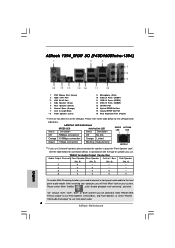
... Speaker Jack". Choose "2CH", "4CH", "6CH", or "8CH" and then you need to connect a front panel audio cable to use front panel audio. 6 ASRock Motherboard English See the table below for Audio Output Connection Audio Output Channels Front Speaker Rear Speaker Central / Bass (No. 7) (No. 4) (No. 5) 2 ...Central/Bass, and Front Speaker, or select "Realtek HDA Audio 2nd output" to the front panel audio header. ASRock SPDIF I/O (P43Twins1600) 1 PS/2 Mouse Port (Green) 2 LAN RJ-45 Port 3 Side Speaker (Gray) 4 Rear Speaker (Black) 5 Central / Bass (Orange) 6 Line In (Light...
... Speaker Jack". Choose "2CH", "4CH", "6CH", or "8CH" and then you need to connect a front panel audio cable to use front panel audio. 6 ASRock Motherboard English See the table below for Audio Output Connection Audio Output Channels Front Speaker Rear Speaker Central / Bass (No. 7) (No. 4) (No. 5) 2 ...Central/Bass, and Front Speaker, or select "Realtek HDA Audio 2nd output" to the front panel audio header. ASRock SPDIF I/O (P43Twins1600) 1 PS/2 Mouse Port (Green) 2 LAN RJ-45 Port 3 Side Speaker (Gray) 4 Rear Speaker (Black) 5 Central / Bass (Orange) 6 Line In (Light...
Quick Installation Guide
Page 8
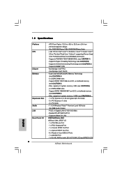
...Yorkfield and Dual Core Wolfdale processors - Southbridge: Intel® ICH10 - Max. Max. All Solid Capacitor design (For P43D1600Twins-1394 / P43D1600Twins Only) - Supports Hyper-Threading Technology (see CAUTION 5) - Support DDR3 1333/1066 non-ECC, un-buffered memory (...-LAN P43D1600Twins-1394 ASRock 1394_SPDIF I /O 8 - 1.2 Specifications Platform CPU Chipset Memory Expansion Slot Audio LAN Rear Panel I /O - 1 x PS/2 Mouse Port - 1 x PS/2 Keyboard Port - 1 x Coaxial SPDIF Out Port - 1 x Optical SPDIF Out Port - 6 x Ready-to-Use USB 2.0 Ports - 1 x eSATAII Port - 1 x RJ-45 LAN Port with LED...
...Yorkfield and Dual Core Wolfdale processors - Southbridge: Intel® ICH10 - Max. Max. All Solid Capacitor design (For P43D1600Twins-1394 / P43D1600Twins Only) - Supports Hyper-Threading Technology (see CAUTION 5) - Support DDR3 1333/1066 non-ECC, un-buffered memory (...-LAN P43D1600Twins-1394 ASRock 1394_SPDIF I /O 8 - 1.2 Specifications Platform CPU Chipset Memory Expansion Slot Audio LAN Rear Panel I /O - 1 x PS/2 Mouse Port - 1 x PS/2 Keyboard Port - 1 x Coaxial SPDIF Out Port - 1 x Optical SPDIF Out Port - 6 x Ready-to-Use USB 2.0 Ports - 1 x eSATAII Port - 1 x RJ-45 LAN Port with LED...
Quick Installation Guide
Page 9
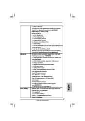
... pin ATX power connector - 8 pin 12V power connector (P43D1600Twins-1394 / P43D1600Twins) - 4 pin 12V power connector (P43Twins1600) - CD in /Front Speaker/Microphone (see CAUTION 7) P43D1600Twins / P43Twins1600 ASRock SPDIF I/O - 1 x PS/2 Mouse Port - 1 x PS/2 Keyboard Port - 1 x Coaxial SPDIF Out Port - 1 x Optical SPDIF Out Port - 6 x Ready-to-Use USB 2.0 Ports - 1 x eSATAII Port - 1 x RJ-45 LAN Port with 1 SATAII port) (see CAUTION 9) - 1 x ATA133 IDE connector (supports 2 x IDE devices...
... pin ATX power connector - 8 pin 12V power connector (P43D1600Twins-1394 / P43D1600Twins) - 4 pin 12V power connector (P43Twins1600) - CD in /Front Speaker/Microphone (see CAUTION 7) P43D1600Twins / P43Twins1600 ASRock SPDIF I/O - 1 x PS/2 Mouse Port - 1 x PS/2 Keyboard Port - 1 x Coaxial SPDIF Out Port - 1 x Optical SPDIF Out Port - 6 x Ready-to-Use USB 2.0 Ports - 1 x eSATAII Port - 1 x RJ-45 LAN Port with 1 SATAII port) (see CAUTION 9) - 1 x ATA133 IDE connector (supports 2 x IDE devices...


