User Manual
Page 3
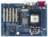
...1.2 Specifications 6 1.3 Motherboard Layout 8 1.4 ASRock I/O PlusTM 9 2 Installation 10 Pre-installation Precautions 10 2.1 CPU Installation 11 2.2 Installation of CPU Fan and Heatsink 11 2.3 Installation of Memory Modules (DIMM 12 2.4 Expansion Slots (PCI and AGP Slots 13 2.5 Jumpers Setup 14 2.6 Onboard Headers and Connectors 15 2.7 Serial ATA (SATA) Hard Disks Installation 18 2.8 Making An SATA Driver Diskette 19 3 BIOS SETUP UTILITY 20 3.1 Introduction 20 3.1.1 BIOS Menu Bar 20 3.1.2 Navigation Keys 21 3.2 Main Screen 21 3.3 Advanced Screen 22 3.3.1 CPU Configuration 22...
...1.2 Specifications 6 1.3 Motherboard Layout 8 1.4 ASRock I/O PlusTM 9 2 Installation 10 Pre-installation Precautions 10 2.1 CPU Installation 11 2.2 Installation of CPU Fan and Heatsink 11 2.3 Installation of Memory Modules (DIMM 12 2.4 Expansion Slots (PCI and AGP Slots 13 2.5 Jumpers Setup 14 2.6 Onboard Headers and Connectors 15 2.7 Serial ATA (SATA) Hard Disks Installation 18 2.8 Making An SATA Driver Diskette 19 3 BIOS SETUP UTILITY 20 3.1 Introduction 20 3.1.1 BIOS Menu Bar 20 3.1.2 Navigation Keys 21 3.2 Main Screen 21 3.3 Advanced Screen 22 3.3.1 CPU Configuration 22...
User Manual
Page 6
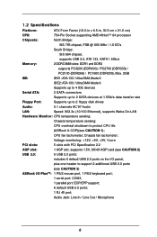
...fan tachometer; Audio Jack: Line In / Line Out / Microphone 6 Voltage monitoring: +12V, +5V, +3V, Vcore PCI slots: 5 slots with PCI Specification 2.2 AGP slot: 1 AGP slot, supports 1.5V, 8X/4X AGP card (see CAUTION 2) USB 2.0: 8 USB 2.0 ports: includes 6 default USB 2.0 ports on the I /O PlusTM: 1 PS/2 mouse port, 1 PS/2 keyboard port; 1 serial port: COM1; 1 parallel port: ECP/EPP support; 6 default USB 2.0 ports; 1 RJ 45 port; Chassis temperature sensing; 1.2 Specifications Platform: CPU: ATX Form Factor (12.0-in x 8.5-in, 30.5 cm x 21.6 cm) 754-Pin Socket supporting AMD...
...fan tachometer; Audio Jack: Line In / Line Out / Microphone 6 Voltage monitoring: +12V, +5V, +3V, Vcore PCI slots: 5 slots with PCI Specification 2.2 AGP slot: 1 AGP slot, supports 1.5V, 8X/4X AGP card (see CAUTION 2) USB 2.0: 8 USB 2.0 ports: includes 6 default USB 2.0 ports on the I /O PlusTM: 1 PS/2 mouse port, 1 PS/2 keyboard port; 1 serial port: COM1; 1 parallel port: ECP/EPP support; 6 default USB 2.0 ports; 1 RJ 45 port; Chassis temperature sensing; 1.2 Specifications Platform: CPU: ATX Form Factor (12.0-in x 8.5-in, 30.5 cm x 21.6 cm) 754-Pin Socket supporting AMD...
User Manual
Page 7
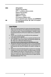
....microsoft.com/whdc/hwdev/bus/USB/USB2support.mspx 4. When the official 64 bit drivers are in the ASRock support CD-ROM under "XP64DRV_beta" folder are available, ASRock Inc. BIOS: OS: AMI legal BIOS; Supports "Plug and Play"; Please check if the CPU fan on the AGP slot of the system or damage the CPU. 5. Power Management for USB 2.0 works fine under Microsoft® Windows® 98/ ME. Supports "Plug and Play"; will...
....microsoft.com/whdc/hwdev/bus/USB/USB2support.mspx 4. When the official 64 bit drivers are in the ASRock support CD-ROM under "XP64DRV_beta" folder are available, ASRock Inc. BIOS: OS: AMI legal BIOS; Supports "Plug and Play"; Please check if the CPU fan on the AGP slot of the system or damage the CPU. 5. Power Management for USB 2.0 works fine under Microsoft® Windows® 98/ ME. Supports "Plug and Play"; will...
User Manual
Page 8
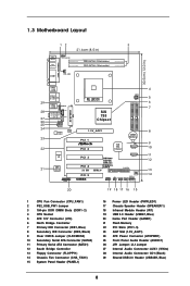
...184-pin DDR DIMM Slots (DDR1- 2) 4 CPU Socket 5 ATX 12V Connector (U74) 6 North Bridge Controller 7 Primary IDE Connector (IDE1, Blue) 8 Secondary IDE Connector (IDE2, Black) 9 Clear CMOS Jumper (CLRCMOS2) 10 Secondary Serial ATA Connector (SATA2) 11 Primary Serial ATA Connector (SATA1) 12 South Bridge Controller 13 Floppy Connector (FLOPPY1) 14 Chassis Fan Connector (CHA_FAN1) 15 System Panel Header (PANEL1) 16 Power LED Header (PWRLED1) 17 Chassis Speaker Header (SPEAKER 1) 18 Infrared Module Header (IR1) 19 USB 2.0 Header (USB67, Blue) 20 Game Port Header (GAME1) 21 Flash...
...184-pin DDR DIMM Slots (DDR1- 2) 4 CPU Socket 5 ATX 12V Connector (U74) 6 North Bridge Controller 7 Primary IDE Connector (IDE1, Blue) 8 Secondary IDE Connector (IDE2, Black) 9 Clear CMOS Jumper (CLRCMOS2) 10 Secondary Serial ATA Connector (SATA2) 11 Primary Serial ATA Connector (SATA1) 12 South Bridge Controller 13 Floppy Connector (FLOPPY1) 14 Chassis Fan Connector (CHA_FAN1) 15 System Panel Header (PANEL1) 16 Power LED Header (PWRLED1) 17 Chassis Speaker Header (SPEAKER 1) 18 Infrared Module Header (IR1) 19 USB 2.0 Header (USB67, Blue) 20 Game Port Header (GAME1) 21 Flash...
User Manual
Page 15
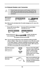
... connect the black end to the motherboard to the instruction of the connector. Please refer to the IDE devices 80-conductor ATA 66/100/133 cable Note: If you use only one IDE device on the motherboard. 15 Placing jumper caps over these headers and connectors. The current SATA interface allows up to the SATA hard disk or the SATA connector on this motherboard, please set the IDE device as "Master". Primary IDE Connector (Blue) (39-pin...
... connect the black end to the motherboard to the instruction of the connector. Please refer to the IDE devices 80-conductor ATA 66/100/133 cable Note: If you use only one IDE device on the motherboard. 15 Placing jumper caps over these headers and connectors. The current SATA interface allows up to the SATA hard disk or the SATA connector on this motherboard, please set the IDE device as "Master". Primary IDE Connector (Blue) (39-pin...
User Manual
Page 16
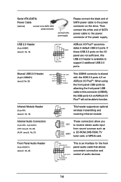
... power connector of SATA power cable to support 2 additional USB 2.0 ports. 1 USB_PWR P-4 P+4 GND USB_PWR P-5 P+5 GND DUMMY This USB45 connector is an interface for the front panel audio cable that allows convenient connection and control of audio devices. 16 When using the front panel USB ports by attaching the front panel USB cable to this connector (USB45), the USB ports 4,5 on ASRock I /O panel are not sufficient, this USB 2.0 header is available to the power connector on the drive. O U T- Infrared Module Header (5-pin IR1) (see p.8, No. 18) Internal Audio Connectors (4-pin...
... power connector of SATA power cable to support 2 additional USB 2.0 ports. 1 USB_PWR P-4 P+4 GND USB_PWR P-5 P+5 GND DUMMY This USB45 connector is an interface for the front panel audio cable that allows convenient connection and control of audio devices. 16 When using the front panel USB ports by attaching the front panel USB cable to this connector (USB45), the USB ports 4,5 on ASRock I /O panel are not sufficient, this USB 2.0 header is available to the power connector on the drive. O U T- Infrared Module Header (5-pin IR1) (see p.8, No. 18) Internal Audio Connectors (4-pin...
User Manual
Page 18
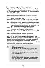
... "Hot Swap" for SATA Devices. If SATA HDDs are NOT set for RAID configuration, it is still power-on and in working condition. STEP 4: Connect the SATA power cable to the SATA hard disk. 2.8 Hot Plug and Hot Swap Functions for SATA HDDs K8S8X motherboard supports Hot Plug function for the action to insert and remove the SATA HDDs while the system is Hot Swap Function? 2.7 Serial ATA (SATA) Hard Disks Installation This motherboard adopts SiS 964 southbridge chipset that supports Serial ATA (SATA) hard disks and RAID functions.
... "Hot Swap" for SATA Devices. If SATA HDDs are NOT set for RAID configuration, it is still power-on and in working condition. STEP 4: Connect the SATA power cable to the SATA hard disk. 2.8 Hot Plug and Hot Swap Functions for SATA HDDs K8S8X motherboard supports Hot Plug function for the action to insert and remove the SATA HDDs while the system is Hot Swap Function? 2.7 Serial ATA (SATA) Hard Disks Installation This motherboard adopts SiS 964 southbridge chipset that supports Serial ATA (SATA) hard disks and RAID functions.
User Manual
Page 20
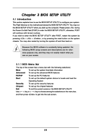
... following BIOS setup screens and descriptions are for reference purpose only, and they may also restart by pressing the reset button on . Because the BIOS software is constantly being updated, the following selections: Main To set up the system time/date information Advanced To set up the advanced BIOS features PCIPnP To set up the PCI features Boot To set up the default system device to locate and load the...
... following BIOS setup screens and descriptions are for reference purpose only, and they may also restart by pressing the reset button on . Because the BIOS software is constantly being updated, the following selections: Main To set up the system time/date information Advanced To set up the advanced BIOS features PCIPnP To set up the PCI features Boot To set up the default system device to locate and load the...
User Manual
Page 22
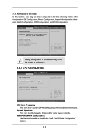
..., American Megatrends, Inc. Main BIOS SETUP UTILITY Advanced PCI PnP Boot Security Chipset Exit Advanced Settings WARNING : Setting wrong values in this item to enable or disable the "AMD Cool 'N Quiet Configuration" feature. 22 CPU Configuration IDE Configuration Floppy Configuration SuperIO Configuration Hardware Health Configuration ACPI Configuration USB Configuration Options for better system stability. Spread Spectrum This item should always be [Disabled] for CPU Select Screen Select Item Enter Go to Sub Screen F1 General Help F9 Load Defaults F10 Save and Exit...
..., American Megatrends, Inc. Main BIOS SETUP UTILITY Advanced PCI PnP Boot Security Chipset Exit Advanced Settings WARNING : Setting wrong values in this item to enable or disable the "AMD Cool 'N Quiet Configuration" feature. 22 CPU Configuration IDE Configuration Floppy Configuration SuperIO Configuration Hardware Health Configuration ACPI Configuration USB Configuration Options for better system stability. Spread Spectrum This item should always be [Disabled] for CPU Select Screen Select Item Enter Go to Sub Screen F1 General Help F9 Load Defaults F10 Save and Exit...
User Manual
Page 23
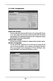
...following instruction, which can be applied to the configurations of device connected to enable or disable the "OnBoard SATA Controller" feature. Configuration options: [Disabled], [Primary], [Secondary], [Both]. OnBoard SATA Controller Use this item to the system. +F1 F9 F10 ESC Select Screen Select Item Change Option General Help Load Defaults Save and Exit Exit v02.54 (C) Copyright 1985-2003, American Megatrends, Inc. 23 3.3.2 IDE Configuration BIOS SETUP UTILITY Advanced IDE Configuration OnBoard IDE Controller OnBoard SATA Controller Primary IDE Master Primary IDE Slave...
...following instruction, which can be applied to the configurations of device connected to enable or disable the "OnBoard SATA Controller" feature. Configuration options: [Disabled], [Primary], [Secondary], [Both]. OnBoard SATA Controller Use this item to the system. +F1 F9 F10 ESC Select Screen Select Item Change Option General Help Load Defaults Save and Exit Exit v02.54 (C) Copyright 1985-2003, American Megatrends, Inc. 23 3.3.2 IDE Configuration BIOS SETUP UTILITY Advanced IDE Configuration OnBoard IDE Controller OnBoard SATA Controller Primary IDE Master Primary IDE Slave...
User Manual
Page 24
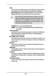
... hard disk drive. DMA Mode DMA capability allows the improved transfer-speed and data-integrity for Netware and UNIX user, select [Disabled] to enable or disable the S.M.A.R.T. (Self-Monitoring, Analysis, and Reporting Technology) feature. If this feature is [Auto]. Configuration options: [Disabled], [Auto], [Enabled]. 32 Bit Data Transfer Use this item to select the LBA/Large mode for a hard disk > 512 MB under DOS and Windows; Make sure to set the PIO mode to enhance hard disk...
... hard disk drive. DMA Mode DMA capability allows the improved transfer-speed and data-integrity for Netware and UNIX user, select [Disabled] to enable or disable the S.M.A.R.T. (Self-Monitoring, Analysis, and Reporting Technology) feature. If this feature is [Auto]. Configuration options: [Disabled], [Auto], [Enabled]. 32 Bit Data Transfer Use this item to select the LBA/Large mode for a hard disk > 512 MB under DOS and Windows; Make sure to set the PIO mode to enhance hard disk...
User Manual
Page 25
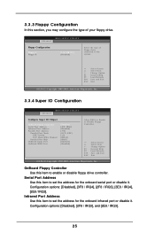
...]. OnBoard Floppy Controller Use this section, you may configure the type of floppy drive connected to the system. +F1 F9 F10 ESC Select Screen Select Item Change Option General Help Load Defaults Save and Exit Exit v02.54 (C) Copyright 1985-2003, American Megatrends, Inc. 3.3.4 Super IO Configuration BIOS SETUP UTILITY Advanced Configure Super IO Chipset OnBoard Floppy Controller Serial Port Address Infrared Port Address Parallel Port Address Parallel Port Mode EPP Version ECP Mode DMA Channel Parallel Port IRQ OnBoard Game Port OnBoard MIDI Port [Enabled] [3F8 / IRQ4] [Disabled...
...]. OnBoard Floppy Controller Use this section, you may configure the type of floppy drive connected to the system. +F1 F9 F10 ESC Select Screen Select Item Change Option General Help Load Defaults Save and Exit Exit v02.54 (C) Copyright 1985-2003, American Megatrends, Inc. 3.3.4 Super IO Configuration BIOS SETUP UTILITY Advanced Configure Super IO Chipset OnBoard Floppy Controller Serial Port Address Infrared Port Address Parallel Port Address Parallel Port Mode EPP Version ECP Mode DMA Channel Parallel Port IRQ OnBoard Game Port OnBoard MIDI Port [Enabled] [3F8 / IRQ4] [Disabled...
User Manual
Page 27
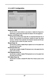
... the power recovers. 3.3.6 ACPI Configuration Advanced BIOS SETUP UTILITY ACPI Settings Suspend To RAM Restore on AC/Power Loss Use this feature if the OS supports it. RTC Alarm Power On Use this item to enable or disable Ring-In signals to auto-detect or disable the Suspend-toRAM feature. If [Power On] is selected, the AC/power remains off mode. Restore on AC / Power Loss Ring-In Power On PCI Devices Power On PS / 2 Keyboard Power On...
... the power recovers. 3.3.6 ACPI Configuration Advanced BIOS SETUP UTILITY ACPI Settings Suspend To RAM Restore on AC/Power Loss Use this feature if the OS supports it. RTC Alarm Power On Use this item to enable or disable Ring-In signals to auto-detect or disable the Suspend-toRAM feature. If [Power On] is selected, the AC/power remains off mode. Restore on AC / Power Loss Ring-In Power On PCI Devices Power On PS / 2 Keyboard Power On...
User Manual
Page 28
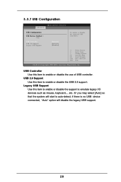
... is no USB device connected, "Auto" option will start to enable or disable the USB 2.0 support. Legacy USB Support Use this item to auto-detect; etc. USB 2.0 Support Use this item to enable or disable the support to enable or disable the use of USB controller. 3.3.7 USB Configuration BIOS SETUP UTILITY Advanced USB Configuration USB Devices Enabled : None USB Controller USB 2.0 Support Legacy USB Support [Enabled] [Enabled] [Disabled] To enable or disable the onboard USB controllers. +F1 F9 F10 ESC Select Screen Select Item Change Option General Help Load Defaults Save and...
... is no USB device connected, "Auto" option will start to enable or disable the USB 2.0 support. Legacy USB Support Use this item to auto-detect; etc. USB 2.0 Support Use this item to enable or disable the support to enable or disable the use of USB controller. 3.3.7 USB Configuration BIOS SETUP UTILITY Advanced USB Configuration USB Devices Enabled : None USB Controller USB 2.0 Support Legacy USB Support [Enabled] [Enabled] [Disabled] To enable or disable the onboard USB controllers. +F1 F9 F10 ESC Select Screen Select Item Change Option General Help Load Defaults Save and...
User Manual
Page 29
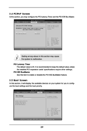
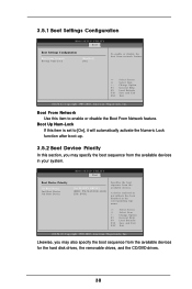
BIOS SETUP UTILITY Main Advanced PCIPnP Boot Security Chipset Exit Boot Settings Boot Settings Configuration Boot Device Priority Hard Disk Drives Removable Drives CD / DVD Drives Configure Settings during System Boot. Main Advanced BIOS SETUP UTILITY PCIPnP Boot Security Chipset Exit Advanced PCI / PnP Settings WARNING : Setting wrong values in below sections may configure the PCI Latency Timer and the PCI IDE Bus Master. It is 64. PCI IDE BusMaster Use this item to enable or disable the PCI IDE BusMaster feature. 3.5 Boot Screen In this section, it will display the ...
BIOS SETUP UTILITY Main Advanced PCIPnP Boot Security Chipset Exit Boot Settings Boot Settings Configuration Boot Device Priority Hard Disk Drives Removable Drives CD / DVD Drives Configure Settings during System Boot. Main Advanced BIOS SETUP UTILITY PCIPnP Boot Security Chipset Exit Advanced PCI / PnP Settings WARNING : Setting wrong values in below sections may configure the PCI Latency Timer and the PCI IDE Bus Master. It is 64. PCI IDE BusMaster Use this item to enable or disable the PCI IDE BusMaster feature. 3.5 Boot Screen In this section, it will display the ...
User Manual
Page 30
..., Inc. Boot From Network Use this item to [On], it will automatically activate the Numeric Lock function after boot-up. 3.5.2 Boot Device Priority In this item is set to enable or disable the Boot From Network feature. Boot Device Priority 1st Boot Device 2nd Boot Device 3rd Boot Device BIOS SETUP UTILITY Boot [1st FLOPPY DRIVE] [HDD: PM-MAXTOR 6L08] [CD / DVD] Specifies the boot sequence from network feature. +F1 F9 F10 ESC Select Screen Select Item Change Option General Help Load Defaults Save...
..., Inc. Boot From Network Use this item to [On], it will automatically activate the Numeric Lock function after boot-up. 3.5.2 Boot Device Priority In this item is set to enable or disable the Boot From Network feature. Boot Device Priority 1st Boot Device 2nd Boot Device 3rd Boot Device BIOS SETUP UTILITY Boot [1st FLOPPY DRIVE] [HDD: PM-MAXTOR 6L08] [CD / DVD] Specifies the boot sequence from network feature. +F1 F9 F10 ESC Select Screen Select Item Change Option General Help Load Defaults Save...
User Manual
Page 31
Main Advanced BIOS SETUP UTILITY PCIPnP Boot Security Chipset Exit Chipset Settings Memory Controller Configuration SouthBridge Configuration AGP Configuration HyperTransport Configuration Options for NB Select Screen Select Item Enter Go to Sub Screen F1 General Help F9 Load Defaults F10 Save and Exit ESC Exit v02.54 (C) Copyright 1985-2003, American Megatrends, Inc. 31 Select Screen Select Item Enter Change F1 General Help F9 Load Defaults F10 Save and Exit ESC Exit v02.54 (C) Copyright 1985...
Main Advanced BIOS SETUP UTILITY PCIPnP Boot Security Chipset Exit Chipset Settings Memory Controller Configuration SouthBridge Configuration AGP Configuration HyperTransport Configuration Options for NB Select Screen Select Item Enter Go to Sub Screen F1 General Help F9 Load Defaults F10 Save and Exit ESC Exit v02.54 (C) Copyright 1985-2003, American Megatrends, Inc. 31 Select Screen Select Item Enter Change F1 General Help F9 Load Defaults F10 Save and Exit ESC Exit v02.54 (C) Copyright 1985...
User Manual
Page 34
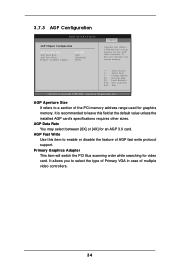
... This item will switch the PCI Bus scanning order while searching for an AGP 3.0 card. AGP Fast Write Use this field at the default value unless the installed AGP card's specifications requires other sizes. It is recommended to leave this item to select the type of Primary VGA in case of the PCI memory address range used for the AGP video controller. 3.7.3 AGP Configuration BIOS SETUP UTILITY AGP Chipset Configuration AGP Aperture Size AGP Data...
... This item will switch the PCI Bus scanning order while searching for an AGP 3.0 card. AGP Fast Write Use this field at the default value unless the installed AGP card's specifications requires other sizes. It is recommended to leave this item to select the type of Primary VGA in case of the PCI memory address range used for the AGP video controller. 3.7.3 AGP Configuration BIOS SETUP UTILITY AGP Chipset Configuration AGP Aperture Size AGP Data...
User Manual
Page 35
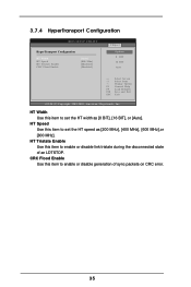
HT Speed Use this item to set the HT width as [200 MHz], [400 MHz], [600 MHz],or [800 MHz]. CRC Flood Enable Use this item to enable or disable generation of an LDTSTOP. 3.7.4 HyperTransport Configuration BIOS SETUP UTILITY HyperTransport Configuration HT Width HT Speed HT Tristate Enable CRC Flood Enable [Auto] [800 Mhz] [Disabled] [Disabled] Chipset Options 8 BIT 16 BIT Auto +F1 F9 F10 ESC Select Screen Select Item Change Option General Help Load Defaults Save and Exit...
HT Speed Use this item to set the HT width as [200 MHz], [400 MHz], [600 MHz],or [800 MHz]. CRC Flood Enable Use this item to enable or disable generation of an LDTSTOP. 3.7.4 HyperTransport Configuration BIOS SETUP UTILITY HyperTransport Configuration HT Width HT Speed HT Tristate Enable CRC Flood Enable [Auto] [800 Mhz] [Disabled] [Disabled] Chipset Options 8 BIT 16 BIT Auto +F1 F9 F10 ESC Select Screen Select Item Change Option General Help Load Defaults Save and Exit...
User Manual
Page 37
... file. 4.2.5 Contact Information If you may contact your CD-ROM drive. Please install the necessary drivers to your OS documentation for general reference only. or you need to contact ASRock or want to know more information. 4.2 Support CD Information The Support CD that came with the motherboard contains necessary drivers and useful utilities that the motherboard supports. Chapter 4 Software Support 4.1 Install Operating System This motherboard supports various Microsoft® Windows...
... file. 4.2.5 Contact Information If you may contact your CD-ROM drive. Please install the necessary drivers to your OS documentation for general reference only. or you need to contact ASRock or want to know more information. 4.2 Support CD Information The Support CD that came with the motherboard contains necessary drivers and useful utilities that the motherboard supports. Chapter 4 Software Support 4.1 Install Operating System This motherboard supports various Microsoft® Windows...


