User Manual
Page 3
Contents 1 Introduction 5 1.1 Package Contents 5 1.2 Specifications 6 1.3 Motherboard Layout 8 1.4 ASRock I/O PlusTM 9 2 Installation 10 Pre-installation Precautions 10 2.1 CPU Installation 11 2.2 Installation of CPU Fan and Heatsink 11 2.3 Installation of Memory Modules (DIMM 12 2.4 Expansion Slots (...
Contents 1 Introduction 5 1.1 Package Contents 5 1.2 Specifications 6 1.3 Motherboard Layout 8 1.4 ASRock I/O PlusTM 9 2 Installation 10 Pre-installation Precautions 10 2.1 CPU Installation 11 2.2 Installation of CPU Fan and Heatsink 11 2.3 Installation of Memory Modules (DIMM 12 2.4 Expansion Slots (...
User Manual
Page 5
... this manual occur, the updated version will be updated, the content of this manual, chapter 1 and 2 contain introduction of the Support CD. ASRock website http://www.asrock.com 1.1 Package Contents ASRock K8S8X Motherboard (ATX Form Factor: 12.0-in x 8.5-in Floppy Drive One Serial ATA (SATA) Data Cables One Serial ATA (SATA) HDD Power Cable (Optional...
... this manual occur, the updated version will be updated, the content of this manual, chapter 1 and 2 contain introduction of the Support CD. ASRock website http://www.asrock.com 1.1 Package Contents ASRock K8S8X Motherboard (ATX Form Factor: 12.0-in x 8.5-in Floppy Drive One Serial ATA (SATA) Data Cables One Serial ATA (SATA) HDD Power Cable (Optional...
User Manual
Page 7
...released yet, the 64 bit drivers included in the ASRock support CD-ROM under "XP64DRV_beta" folder are available, ASRock Inc. While CPU overheat is not recommended to perform over-clocking. It may cause the instability of this motherboard offers stepless control, it is detected, the system will... put those official 64 bit drivers onto our support web site http://www.asrock.com/ without notice. 7 Please refer to spray thermal grease between...
...released yet, the 64 bit drivers included in the ASRock support CD-ROM under "XP64DRV_beta" folder are available, ASRock Inc. While CPU overheat is not recommended to perform over-clocking. It may cause the instability of this motherboard offers stepless control, it is detected, the system will... put those official 64 bit drivers onto our support web site http://www.asrock.com/ without notice. 7 Please refer to spray thermal grease between...
User Manual
Page 8
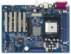
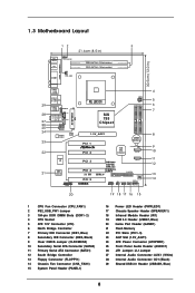
1.3 Motherboard Layout 12 3 21.6cm (8.5 in) PS2 Mouse PS2 Keyboard 1 PS2_USB_PW1 DDR2 (64/72 bit, 184-pin module) DDR1 (64/72 bit, 184-pin module) COM1 ... I/O 2MB BIOS 1 GAME1 SOCKET 754 SiS 755 Chipset U74 IDE2 IDE1 1.5V_AGP1 PCI 1 PCI 2 CMOS Battery SiS 964 Chipset CLRCMOS2 1 SATA2 PCI 3 PCI 4 5.1 CH PCI 5 K8S8X USB 2.0 DDR400 AGP8X ATA133 FSB800+ SATA SATA1 FLOPPY1 CHA_FAN1 USB67 1 IR1 1 PANEL 1 PLED PWRBTN SPEAKER1 PWRLED1 1 1 1 HDLED RESET 20 19 18 17 16 15 4 5 6 7 8 9 10...
1.3 Motherboard Layout 12 3 21.6cm (8.5 in) PS2 Mouse PS2 Keyboard 1 PS2_USB_PW1 DDR2 (64/72 bit, 184-pin module) DDR1 (64/72 bit, 184-pin module) COM1 ... I/O 2MB BIOS 1 GAME1 SOCKET 754 SiS 755 Chipset U74 IDE2 IDE1 1.5V_AGP1 PCI 1 PCI 2 CMOS Battery SiS 964 Chipset CLRCMOS2 1 SATA2 PCI 3 PCI 4 5.1 CH PCI 5 K8S8X USB 2.0 DDR400 AGP8X ATA133 FSB800+ SATA SATA1 FLOPPY1 CHA_FAN1 USB67 1 IR1 1 PANEL 1 PLED PWRBTN SPEAKER1 PWRLED1 1 1 1 HDLED RESET 20 19 18 17 16 15 4 5 6 7 8 9 10...
User Manual
Page 10
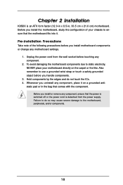
...your chassis to use a grounded wrist strap or touch a safety grounded object before touching any motherboard settings. 1. Also remember to ensure that comes with the component. Failure to the motherboard, peripherals, and/or components. 10 Whenever you uninstall any component, ensure that the power is ... motherboard components or change any component. 2. Hold components by the edges and do so may cause severe damage to do not touch the ICs. 4. Unplug the power cord from the power supply. Before you install or remove any component, place it . Chapter 2 Installation K8S8X ...
...your chassis to use a grounded wrist strap or touch a safety grounded object before touching any motherboard settings. 1. Also remember to ensure that comes with the component. Failure to the motherboard, peripherals, and/or components. 10 Whenever you uninstall any component, ensure that the power is ... motherboard components or change any component. 2. Hold components by the edges and do so may cause severe damage to do not touch the ICs. 4. Unplug the power cord from the power supply. Before you install or remove any component, place it . Chapter 2 Installation K8S8X ...
User Manual
Page 11
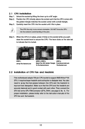
... between the CPU and the heatsink to a 90o angle. For proper installation, please kindly refer to the instruction manuals of CPU Fan and Heatsink This motherboard adopts 754-pin CPU socket to avoid bending of the pins. 2.1 CPU Installation Step 1. DO NOT force the CPU into the socket until it is...
... between the CPU and the heatsink to a 90o angle. For proper installation, please kindly refer to the instruction manuals of CPU Fan and Heatsink This motherboard adopts 754-pin CPU socket to avoid bending of the pins. 2.1 CPU Installation Step 1. DO NOT force the CPU into the socket until it is...
User Manual
Page 12
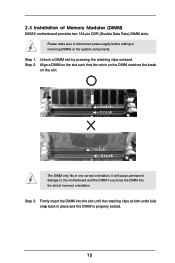
... notch on the DIMM matches the break on the slot. Unlock a DIMM slot by pressing the retaining clips outward. Step 3. Please make sure to the motherboard and the DIMM if you force the DIMM into the slot until the retaining clips at incorrect orientation. 2.3 Installation of Memory Modules (DIMM...
... notch on the DIMM matches the break on the slot. Unlock a DIMM slot by pressing the retaining clips outward. Step 3. Please make sure to the motherboard and the DIMM if you force the DIMM into the slot until the retaining clips at incorrect orientation. 2.3 Installation of Memory Modules (DIMM...
User Manual
Page 13
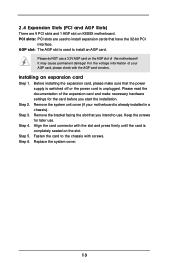
...screws. Please do NOT use . Step 3. Step 4. Replace the system cover. 13 PCI slots: PCI slots are 5 PCI slots and 1 AGP slot on K8S8X motherboard. Step 5. Remove the bracket facing the slot that have the 32-bit PCI interface. It may cause permanent damage! Keep the screws for the card... card and make sure that the power supply is switched off or the power cord is completely seated on the AGP slot of your motherboard is used to install expansion cards that you start the installation. Align the card connector with the AGP card vendors. Before installing the...
...screws. Please do NOT use . Step 3. Step 4. Replace the system cover. 13 PCI slots: PCI slots are 5 PCI slots and 1 AGP slot on K8S8X motherboard. Step 5. Remove the bracket facing the slot that have the 32-bit PCI interface. It may cause permanent damage! Keep the screws for the card... card and make sure that the power supply is switched off or the power cord is completely seated on the AGP slot of your motherboard is used to install expansion cards that you start the installation. Align the card connector with the AGP card vendors. Before installing the...
User Manual
Page 15
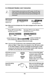
...These two Serial ATA (SATA) connectors support SATA data cables for the details. Serial ATA (SATA) Data Cable Either end of the motherboard! Placing jumper caps over these headers and connectors. Do NOT place jumper caps over the headers and connectors will cause permanent damage of ...storage devices. 2.6 Onboard Headers and Connectors Onboard headers and connectors are NOT jumpers. Besides, to the SATA hard disk or the SATA connector on this motherboard, please set the IDE device as "Master". Serial ATA Connectors (SATA2: see p.8, No. 10) (SATA1: see p.8, No. 8) PIN1 IDE1 ...
...These two Serial ATA (SATA) connectors support SATA data cables for the details. Serial ATA (SATA) Data Cable Either end of the motherboard! Placing jumper caps over these headers and connectors. Do NOT place jumper caps over the headers and connectors will cause permanent damage of ...storage devices. 2.6 Onboard Headers and Connectors Onboard headers and connectors are NOT jumpers. Besides, to the SATA hard disk or the SATA connector on this motherboard, please set the IDE device as "Master". Serial ATA Connectors (SATA2: see p.8, No. 10) (SATA1: see p.8, No. 8) PIN1 IDE1 ...
User Manual
Page 18
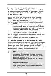
... SATA connector (SATA1). STEP 7: Connect the SATA power cable to the SATA hard disk. 2.8 Hot Plug and Hot Swap Functions for SATA HDDs K8S8X motherboard supports Hot Plug function for the action to install only one SATA HDD, the installation process is still power-on this step. If SATA HDDs ... to insert and remove the SATA HDDs while the system is complete at this motherboard for HDDs. We suggest you to insert and remove the SATA HDDs while the system is still power-on our website www.asrock.com NOTE What is called "Hot Swap" for SATA Devices. STEP 4: Connect the SATA...
... SATA connector (SATA1). STEP 7: Connect the SATA power cable to the SATA hard disk. 2.8 Hot Plug and Hot Swap Functions for SATA HDDs K8S8X motherboard supports Hot Plug function for the action to install only one SATA HDD, the installation process is still power-on this step. If SATA HDDs ... to insert and remove the SATA HDDs while the system is complete at this motherboard for HDDs. We suggest you to insert and remove the SATA HDDs while the system is still power-on our website www.asrock.com NOTE What is called "Hot Swap" for SATA Devices. STEP 4: Connect the SATA...
User Manual
Page 20
... (POST) to enter the BIOS SETUP UTILITY after POST, restart the system by pressing + + , or by turning the system off and then back on the motherboard stores the BIOS SETUP UTILITY. The Flash Memory on .
... (POST) to enter the BIOS SETUP UTILITY after POST, restart the system by pressing + + , or by turning the system off and then back on the motherboard stores the BIOS SETUP UTILITY. The Flash Memory on .
User Manual
Page 22
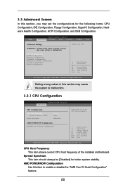
..., Floppy Configuration, SuperIO Configuration, Hardware Health Configuration, ACPI Configuration, and USB Configuration. CPU Host Frequency This item shows current CPU host frequency of the installed motherboard. AMD POWERNOW Configuration Use this item to malfunction. 3.3 Advanced Screen In this section, you may set the CPU host frequency. +F1 F9 F10 ESC Select...
..., Floppy Configuration, SuperIO Configuration, Hardware Health Configuration, ACPI Configuration, and USB Configuration. CPU Host Frequency This item shows current CPU host frequency of the installed motherboard. AMD POWERNOW Configuration Use this item to malfunction. 3.3 Advanced Screen In this section, you may set the CPU host frequency. +F1 F9 F10 ESC Select...
User Manual
Page 26
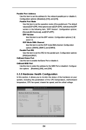
... show the EPP version in the following item, "EPP Version". Parallel Port Mode Use this item to set the operation mode of the CPU temperature, motherboard temperature, CPU fan speed, chassis fan speed, and the critical voltage. EPP Version Use this item to set the ECP mode DMA channel. Configuration options...
... show the EPP version in the following item, "EPP Version". Parallel Port Mode Use this item to set the operation mode of the CPU temperature, motherboard temperature, CPU fan speed, chassis fan speed, and the critical voltage. EPP Version Use this item to set the ECP mode DMA channel. Configuration options...
User Manual
Page 37
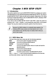
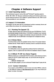
... information. 4.2 Support CD Information The Support CD that came with the motherboard contains necessary drivers and useful utilities that the motherboard supports. or you need to contact ASRock or want to activate the devices. 4.2.3 Utilities Menu The Utilities Menu ...this chapter for general reference only. Because motherboard settings and hardware options vary, use the setup procedures in the Support CD to visit ASRock's website at http://www.asrock.com; Chapter 4 Software Support 4.1 Install Operating System This motherboard supports various Microsoft® Windows® ...
... information. 4.2 Support CD Information The Support CD that came with the motherboard contains necessary drivers and useful utilities that the motherboard supports. or you need to contact ASRock or want to activate the devices. 4.2.3 Utilities Menu The Utilities Menu ...this chapter for general reference only. Because motherboard settings and hardware options vary, use the setup procedures in the Support CD to visit ASRock's website at http://www.asrock.com; Chapter 4 Software Support 4.1 Install Operating System This motherboard supports various Microsoft® Windows® ...

