RAID Installation Guide
Page 8
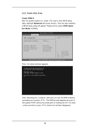
... the main interface of the system POST and boot process prior to enter BIOS setup utility. Advanced BIOS SETUP UTILITY IDE Configuration OnBoard IDE Controller OnBoard SATA Controller SATA Operation Mode Primary IDE Master Primary IDE Slave Secondary IDE Master Secondary IDE Slave SATA1 SATA2 [Both] [Enabled] [RAID] [Hard Disk] [Not Detected] [ATAPI CDROM] [Not Detected] [Not Detected] [Not Detected] Config SATA operation mode. +F1 F10 ESC Select Screen Select Item Change Option General Help Save and Exit Exit v02.53 (C) Copyright 1985-2004. NVIDIA RAID IDE ROM BIOS...
... the main interface of the system POST and boot process prior to enter BIOS setup utility. Advanced BIOS SETUP UTILITY IDE Configuration OnBoard IDE Controller OnBoard SATA Controller SATA Operation Mode Primary IDE Master Primary IDE Slave Secondary IDE Master Secondary IDE Slave SATA1 SATA2 [Both] [Enabled] [RAID] [Hard Disk] [Not Detected] [ATAPI CDROM] [Not Detected] [Not Detected] [Not Detected] Config SATA operation mode. +F1 F10 ESC Select Screen Select Item Change Option General Help Save and Exit Exit v02.53 (C) Copyright 1985-2004. NVIDIA RAID IDE ROM BIOS...
RAID Installation Guide
Page 12
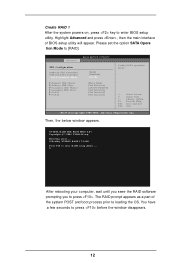
... RAID prompt appears as a part of BIOS setup utility will appear. You have a few seconds to loading the OS. Please set the option SATA Opera tion Mode to enter BIOS setup utility. NVIDIA RAID IDE ROM BIOS 4.81 Copyright (C) 2004 NVIDIA Corp. Advanced BIOS SETUP UTILITY IDE Configuration OnBoard IDE Controller OnBoard SATA Controller SATA Operation Mode Primary IDE Master Primary IDE Slave Secondary IDE Master Secondary IDE Slave SATA1 SATA2 [Both] [Enabled] [RAID] [Hard Disk] [Not Detected] [ATAPI CDROM] [Not Detected] [Not Detected] [Not Detected] Config SATA operation mode...
... RAID prompt appears as a part of BIOS setup utility will appear. You have a few seconds to loading the OS. Please set the option SATA Opera tion Mode to enter BIOS setup utility. NVIDIA RAID IDE ROM BIOS 4.81 Copyright (C) 2004 NVIDIA Corp. Advanced BIOS SETUP UTILITY IDE Configuration OnBoard IDE Controller OnBoard SATA Controller SATA Operation Mode Primary IDE Master Primary IDE Slave Secondary IDE Master Secondary IDE Slave SATA1 SATA2 [Both] [Enabled] [RAID] [Hard Disk] [Not Detected] [ATAPI CDROM] [Not Detected] [Not Detected] [Not Detected] Config SATA operation mode...
RAID Installation Guide
Page 15
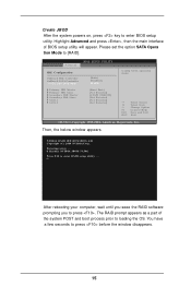
... and press , then the main interface of the system POST and boot process prior to enter RAID setup utility . . . NVIDIA RAID IDE ROM BIOS 4.81 Copyright (C) 2004 NVIDIA Corp. After rebooting your computer, wait until you seee the RAID software prompting you to press before the window disappears. 15 Advanced BIOS SETUP UTILITY IDE Configuration OnBoard IDE Controller OnBoard SATA Controller SATA Operation Mode Primary IDE Master Primary IDE Slave Secondary IDE Master Secondary IDE Slave SATA1 SATA2 [Both] [Enabled] [RAID] [Hard Disk] [Not Detected] [ATAPI...
... and press , then the main interface of the system POST and boot process prior to enter RAID setup utility . . . NVIDIA RAID IDE ROM BIOS 4.81 Copyright (C) 2004 NVIDIA Corp. After rebooting your computer, wait until you seee the RAID software prompting you to press before the window disappears. 15 Advanced BIOS SETUP UTILITY IDE Configuration OnBoard IDE Controller OnBoard SATA Controller SATA Operation Mode Primary IDE Master Primary IDE Slave Secondary IDE Master Secondary IDE Slave SATA1 SATA2 [Both] [Enabled] [RAID] [Hard Disk] [Not Detected] [ATAPI...

User Manual
Page 7
...20 pin ATX power connector - 4 pin 12V power connector - CPU Overheat Shutdown to Protect CPU Life - CPU Fan Tachometer - SMBIOS 2.3.1 Support - Front panel audio connector - 2 x USB 2.0 headers (support 4 USB 2.0 ports) (see CAUTION 7) - CPU Temperature Sensing - ACPI 1.1 Compliance Wake Up Events - FCC, CE, WHQL 7 Microsoft® Windows® 2000 / XP / XP 64-bit compliant - BIOS Feature Support CD Hardware Monitor OS Certifications - 2 x ATA133 IDE connectors (support 4 x IDE devices) - 1 x Floppy connector - AMI Legal BIOS - Chassis Fan Tachometer - Voltage...
...20 pin ATX power connector - 4 pin 12V power connector - CPU Overheat Shutdown to Protect CPU Life - CPU Fan Tachometer - SMBIOS 2.3.1 Support - Front panel audio connector - 2 x USB 2.0 headers (support 4 USB 2.0 ports) (see CAUTION 7) - CPU Temperature Sensing - ACPI 1.1 Compliance Wake Up Events - FCC, CE, WHQL 7 Microsoft® Windows® 2000 / XP / XP 64-bit compliant - BIOS Feature Support CD Hardware Monitor OS Certifications - 2 x ATA133 IDE connectors (support 4 x IDE devices) - 1 x Floppy connector - AMI Legal BIOS - Chassis Fan Tachometer - Voltage...

User Manual
Page 8
... connect SATA hard disk to enable AMD's Cool 'n' QuietTM technology. CAUTION! 1. See APPENDIX on page 40 to SATAII connector directly. 6. While CPU overheat is not recommended to perform over-clocking. Please check the table on page 22 for USB 2.0 works fine under Windows system. You can support AMD's Cool 'n' QuietTM technology, please check AMD's website for proper connection. 5. Although this motherboard supports both stereo and mono modes. Frequencies other than the recommended CPU bus frequencies...
... connect SATA hard disk to enable AMD's Cool 'n' QuietTM technology. CAUTION! 1. See APPENDIX on page 40 to SATAII connector directly. 6. While CPU overheat is not recommended to perform over-clocking. Please check the table on page 22 for USB 2.0 works fine under Windows system. You can support AMD's Cool 'n' QuietTM technology, please check AMD's website for proper connection. 5. Although this motherboard supports both stereo and mono modes. Frequencies other than the recommended CPU bus frequencies...

User Manual
Page 14
... hardware settings for later use . Fasten the card to the chassis with x16 lane width graphics cards. Step 5. Step 6. Remove the bracket facing the slot that the power supply is switched off or the power cord is used to install expansion cards that the value you intend to use . HDMR slot: The HDMR slot is unplugged. Replace the system cover. 2.5 Easy Multi Monitor Feature This motherboard supports Multi Monitor upgrade. If you start the installation. 2.4 Expansion Slots (PCI Express Slots, PCI Slots...
... hardware settings for later use . Fasten the card to the chassis with x16 lane width graphics cards. Step 5. Step 6. Remove the bracket facing the slot that the power supply is switched off or the power cord is used to install expansion cards that the value you intend to use . HDMR slot: The HDMR slot is unplugged. Replace the system cover. 2.5 Easy Multi Monitor Feature This motherboard supports Multi Monitor upgrade. If you start the installation. 2.4 Expansion Slots (PCI Express Slots, PCI Slots...

User Manual
Page 16
... motherboard. Please refer to the instruction of the SATA data cable can be connected to the SATA / SATAII hard disk or the SATAII connector on the I /O accommodates 4 default USB 2.0 ports. Serial ATA (SATA) Power Cable (Optional) connect to the SATA HDD power connector connect to the power supply Please connect the black end of SATA power cable to 3.0 Gb/s data transfer rate. Then connect the white end of SATA power cable to the power connector on this USB 2.0 header is available to support 2 additional USB 2.0 ports. 16 Primary IDE Connector (Blue) (39-pin...
... motherboard. Please refer to the instruction of the SATA data cable can be connected to the SATA / SATAII hard disk or the SATAII connector on the I /O accommodates 4 default USB 2.0 ports. Serial ATA (SATA) Power Cable (Optional) connect to the SATA HDD power connector connect to the power supply Please connect the black end of SATA power cable to 3.0 Gb/s data transfer rate. Then connect the white end of SATA power cable to the power connector on this USB 2.0 header is available to support 2 additional USB 2.0 ports. 16 Primary IDE Connector (Blue) (39-pin...

User Manual
Page 17
... Chipset Configuration. Enter Windows system. Click the icon on the lower right hand taskbar to install your system. 2. Connect Audio_R (RIN) to OUT2_R and Audio_L (LIN) to function correctly. E. High Definition Audio supports Jack Sensing, but the panel wire on the I/O panel are for the front panel audio cable that allows convenient connection and control of audio devices. 1. Set the Front Panel Control option from sound sources such as below: A. If those USB 2.0 ports on the chassis...
... Chipset Configuration. Enter Windows system. Click the icon on the lower right hand taskbar to install your system. 2. Connect Audio_R (RIN) to OUT2_R and Audio_L (LIN) to function correctly. E. High Definition Audio supports Jack Sensing, but the panel wire on the I/O panel are for the front panel audio cable that allows convenient connection and control of audio devices. 1. Set the Front Panel Control option from sound sources such as below: A. If those USB 2.0 ports on the chassis...

User Manual
Page 30
... IDE Controllers. +F1 F9 F10 ESC Select Screen Select Item Change Option General Help Load Defaults Save and Exit Exit v02.54 (C) Copyright 1985-2003, American Megatrends, Inc. The default value of "Primary IDE Slave", "Secondary IDE Master", and "Secondary IDE Slave" as well. 30 3.3.4 IDE Configuration Advanced BIOS SETUP UTILITY IDE Configuration OnBoard IDE Controller OnBoard SATAII Controller SATAII Operation Mode Primary IDE Master Primary IDE Slave Secondary IDE Master Secondary IDE Slave SATAII 1 SATAII 2 [Both] [Enabled] [non-RAID] [Hard Disk...
... IDE Controllers. +F1 F9 F10 ESC Select Screen Select Item Change Option General Help Load Defaults Save and Exit Exit v02.54 (C) Copyright 1985-2003, American Megatrends, Inc. The default value of "Primary IDE Slave", "Secondary IDE Master", and "Secondary IDE Slave" as well. 30 3.3.4 IDE Configuration Advanced BIOS SETUP UTILITY IDE Configuration OnBoard IDE Controller OnBoard SATAII Controller SATAII Operation Mode Primary IDE Master Primary IDE Slave Secondary IDE Master Secondary IDE Slave SATAII 1 SATAII 2 [Both] [Enabled] [non-RAID] [Hard Disk...

User Manual
Page 35
..., motherboard temperature, CPU fan speed, chassis fan speed, and the critical voltage. if there is no USB device connected, "Auto" option will start to enable or disable the use of legacy OS (DOS) such as mouse, keyboard, USB flash... BIOS SETUP UTILITY Main Advanced H/W Monitor Boot Security Exit Hardware Health Event Monitoring CPU Temperature M / B Temperature CPU Fan Speed Chassis Fan Speed Vcore + 3.30V + 5.00V + 12.00V : 37 C / 98 F : 31 C / 87 F : 2833 RPM : N/A : 1.532 V : 3.129 V : 4.877 V : 11.741 V F1 F9 F10 ESC Select Screen Select Item General Help Load Defaults...
..., motherboard temperature, CPU fan speed, chassis fan speed, and the critical voltage. if there is no USB device connected, "Auto" option will start to enable or disable the use of legacy OS (DOS) such as mouse, keyboard, USB flash... BIOS SETUP UTILITY Main Advanced H/W Monitor Boot Security Exit Hardware Health Event Monitoring CPU Temperature M / B Temperature CPU Fan Speed Chassis Fan Speed Vcore + 3.30V + 5.00V + 12.00V : 37 C / 98 F : 31 C / 87 F : 2833 RPM : N/A : 1.532 V : 3.129 V : 4.877 V : 11.741 V F1 F9 F10 ESC Select Screen Select Item General Help Load Defaults...
User Manual
Page 39
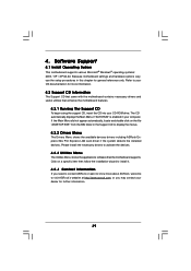
... useful utilities that the motherboard supports. Because motherboard settings and hardware options vary, use the setup procedures in the Support CD to install it. 4.2.4 Contact Information If you may contact your OS documentation for general reference only. If the Main Menu did not appear automatically, locate and double click on a specific item then follow the installation wizard to display the menus. 4.2.2 Drivers Menu The Drivers Menu shows the available devices drivers including ASRock Express GbL PCI Express LAN card driver...
... useful utilities that the motherboard supports. Because motherboard settings and hardware options vary, use the setup procedures in the Support CD to install it. 4.2.4 Contact Information If you may contact your OS documentation for general reference only. If the Main Menu did not appear automatically, locate and double click on a specific item then follow the installation wizard to display the menus. 4.2.2 Drivers Menu The Drivers Menu shows the available devices drivers including ASRock Express GbL PCI Express LAN card driver...

User Manual
Page 40
... to install "AMD Processor Driver" from the "Support CD" first. Switch to enable AMD's Cool 'n' QuietTM technology under Windows system. button. Click the "Power..." Click OK to enable AMD's Cool 'n' QuietTM technology: 1. Double-click the Display icon in the Control Panel then select the Screen Saver tab. 4. From the Power schemes combo list box, select Minimal Power Management. 6. When using Windows 2000/XP operating system, please follow the instruction below to implement settings. 40 Select Settings, then Control Panel. 2.
... to install "AMD Processor Driver" from the "Support CD" first. Switch to enable AMD's Cool 'n' QuietTM technology under Windows system. button. Click the "Power..." Click OK to enable AMD's Cool 'n' QuietTM technology: 1. Double-click the Display icon in the Control Panel then select the Screen Saver tab. 4. From the Power schemes combo list box, select Minimal Power Management. 6. When using Windows 2000/XP operating system, please follow the instruction below to implement settings. 40 Select Settings, then Control Panel. 2.

Quick Installation Guide
Page 3
... to connect a front panel audio cable to share Side Speaker. 3 ASRock K8NF4G-SATA2 Motherboard English Streaming function, you will work but not 8-channel audio. Choose "2CH", "4CH", or "6CH", and then you use 2-channel speaker, please connect the speaker's plug into "Front Speaker Jack". HD 8CH I/O 1 Parallel Port 2 RJ-45 Port 3 Side Speaker (Gray) 4 Rear Speaker (Black) 5 Central / Bass (Orange) 6 Line In (Light Blue) *7 Front Speaker (Lime) 8 Microphone (Pink) 9 USB 2.0 Ports (USB01) 10 USB 2.0 Ports (USB23) 11 VGA Port 12 PS/2 Keyboard Port...
... to connect a front panel audio cable to share Side Speaker. 3 ASRock K8NF4G-SATA2 Motherboard English Streaming function, you will work but not 8-channel audio. Choose "2CH", "4CH", or "6CH", and then you use 2-channel speaker, please connect the speaker's plug into "Front Speaker Jack". HD 8CH I/O 1 Parallel Port 2 RJ-45 Port 3 Side Speaker (Gray) 4 Rear Speaker (Black) 5 Central / Bass (Orange) 6 Line In (Light Blue) *7 Front Speaker (Lime) 8 Microphone (Pink) 9 USB 2.0 Ports (USB01) 10 USB 2.0 Ports (USB23) 11 VGA Port 12 PS/2 Keyboard Port...

Quick Installation Guide
Page 6
... 6 ASRock K8NF4G-SATA2 Motherboard CPU Overheat Shutdown to Protect CPU Life - BIOS Feature Support CD Hardware Monitor OS Certifications - 2 x ATA133 IDE connectors (support 4 x IDE devices) - 1 x Floppy connector - ACPI 1.1 Compliance Wake Up Events - AMI Legal BIOS - Motherboard Temperature Sensing - Microsoft® Windows® 2000 / XP / XP 64-bit compliant - Voltage Monitoring: +12V, +5V, +3.3V, Vcore - CD in header - CPU Frequency Stepless Control (see CAUTION 6) - 4Mb AMI BIOS - Front panel audio connector - 2 x USB 2.0 headers (support 4 USB 2.0 ports...
... 6 ASRock K8NF4G-SATA2 Motherboard CPU Overheat Shutdown to Protect CPU Life - BIOS Feature Support CD Hardware Monitor OS Certifications - 2 x ATA133 IDE connectors (support 4 x IDE devices) - 1 x Floppy connector - ACPI 1.1 Compliance Wake Up Events - AMI Legal BIOS - Motherboard Temperature Sensing - Microsoft® Windows® 2000 / XP / XP 64-bit compliant - Voltage Monitoring: +12V, +5V, +3.3V, Vcore - CD in header - CPU Frequency Stepless Control (see CAUTION 6) - 4Mb AMI BIOS - Front panel audio connector - 2 x USB 2.0 headers (support 4 USB 2.0 ports...
Quick Installation Guide
Page 7
... audio output, this motherboard supports both stereo and mono modes. Frequencies other than the recommended CPU bus frequencies may cause the instability of "User Manual" in the Support CD to enable AMD's Cool 'n' QuietTM technology under Microsoft® Windows® XP SP1 or SP2 / 2000 SP4. 7. Please read the "SATAII Hard Disk Setup Guide" on page 15 to adjust your SATAII hard disk drive to SATA 1.5Gb/s), and connect it back again. Before you install...
... audio output, this motherboard supports both stereo and mono modes. Frequencies other than the recommended CPU bus frequencies may cause the instability of "User Manual" in the Support CD to enable AMD's Cool 'n' QuietTM technology under Microsoft® Windows® XP SP1 or SP2 / 2000 SP4. 7. Please read the "SATAII Hard Disk Setup Guide" on page 15 to adjust your SATAII hard disk drive to SATA 1.5Gb/s), and connect it back again. Before you install...

Quick Installation Guide
Page 10
... can install VGA cards and VGA card drivers to use . The default value of BIOS to adjust the memory capability to insert an ASRock HDMR card with x16 lane width graphics cards. Step 2. Keep the screws for the card before you can easily enjoy the benefits of the system memory. PCIE2 (PCIE x 1 slot) is [Auto], which will disable onboard VGA function when installing VGA card. PCI Slots: PCI slots are 2 PCI Express slots, 2 PCI slots and 1 HDMR slot on PCI Express VGA card, you intend to enjoy multi-monitors. 10 ASRock K8NF4G-SATA2 Motherboard...
... can install VGA cards and VGA card drivers to use . The default value of BIOS to adjust the memory capability to insert an ASRock HDMR card with x16 lane width graphics cards. Step 2. Keep the screws for the card before you can easily enjoy the benefits of the system memory. PCIE2 (PCIE x 1 slot) is [Auto], which will disable onboard VGA function when installing VGA card. PCI Slots: PCI slots are 2 PCI Express slots, 2 PCI slots and 1 HDMR slot on PCI Express VGA card, you intend to enjoy multi-monitors. 10 ASRock K8NF4G-SATA2 Motherboard...
Quick Installation Guide
Page 12
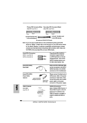
.... USB 2.0 Header (9-pin USB67) (see p.2 No. 17) HD 8CH I /O panel are not sufficient, this motherboard, please set the IDE device as "Master". Serial ATA (SATA) Power Cable (Optional) connect to the SATA HDD power connector connect to the power supply Please connect the black end of your hard disk drive to the primary IDE connector (IDE1, blue) and CD-ROM to the IDE devices 80-conductor ATA 66/100/133 cable Note: If you use only one IDE device on the I /O accommodates 4 default USB 2.0 ports. Serial ATA II Connectors (SATA...
.... USB 2.0 Header (9-pin USB67) (see p.2 No. 17) HD 8CH I /O panel are not sufficient, this motherboard, please set the IDE device as "Master". Serial ATA (SATA) Power Cable (Optional) connect to the SATA HDD power connector connect to the power supply Please connect the black end of your hard disk drive to the primary IDE connector (IDE1, blue) and CD-ROM to the IDE devices 80-conductor ATA 66/100/133 cable Note: If you use only one IDE device on the I /O accommodates 4 default USB 2.0 ports. Serial ATA II Connectors (SATA...
Quick Installation Guide
Page 13
... "Disable front panel jack detection", and save the change by clicking "OK". 13 ASRock K8NF4G-SATA2 Motherboard This connector allows you use AC'97 audio panel, please install it to the front panel audio header as a CD-ROM, DVD-ROM, TV tuner card, or MPEG card. English 1. C. You don't need to MIC2_L. Enter Advanced Settings, and then select Chipset Configuration. Click "Audio I /O accommodates 4 default USB 2.0 ports. High Definition Audio supports Jack Sensing, but the panel wire on the lower right hand taskbar to [Enabled...
... "Disable front panel jack detection", and save the change by clicking "OK". 13 ASRock K8NF4G-SATA2 Motherboard This connector allows you use AC'97 audio panel, please install it to the front panel audio header as a CD-ROM, DVD-ROM, TV tuner card, or MPEG card. English 1. C. You don't need to MIC2_L. Enter Advanced Settings, and then select Chipset Configuration. Click "Audio I /O accommodates 4 default USB 2.0 ports. High Definition Audio supports Jack Sensing, but the panel wire on the lower right hand taskbar to [Enabled...

Quick Installation Guide
Page 15
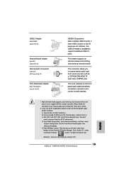
... updates. 15 ASRock K8NF4G-SATA2 Motherboard English On the other hand, if you want to enable SATAII 3.0GB/s, please remove the jumpers from pin 3 and pin 4. SAMSUNG If pin 3 and pin 4 are just for your computer, please carefully read below instruction with the best performance. Please visit HITACHI's website for details: http://www.hitachigst.com/hdd/support/download.htm The above examples are shorted, SATA 1.5GB/s will be enabled...
... updates. 15 ASRock K8NF4G-SATA2 Motherboard English On the other hand, if you want to enable SATAII 3.0GB/s, please remove the jumpers from pin 3 and pin 4. SAMSUNG If pin 3 and pin 4 are just for your computer, please carefully read below instruction with the best performance. Please visit HITACHI's website for details: http://www.hitachigst.com/hdd/support/download.htm The above examples are shorted, SATA 1.5GB/s will be enabled...
Quick Installation Guide
Page 19
If you start up the computer, please press during the Power-On-Self-Test (POST) to enter BIOS Setup utility; It is designed to enter BIOS Setup after POST, please restart the system by pressing + + , or pressing the reset button on the system chassis. For the detailed information about BIOS Setup, please refer to display the menus. 19 ASRock K8NF4G-SATA2 Motherboard English The Support CD that came with its various sub-menus...
If you start up the computer, please press during the Power-On-Self-Test (POST) to enter BIOS Setup utility; It is designed to enter BIOS Setup after POST, please restart the system by pressing + + , or pressing the reset button on the system chassis. For the detailed information about BIOS Setup, please refer to display the menus. 19 ASRock K8NF4G-SATA2 Motherboard English The Support CD that came with its various sub-menus...


