RAID Installation Guide
Page 2
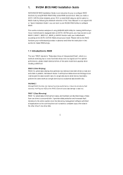
...HDDs amount you can improve the access performance, it will cause data damage or data loss. Please refer to the RAID functions your motherboard according to RAID The term "RAID" stands for creating RAID arrays. It will improve data access and storage since the disk array ...applications to configure RAID. Although RAID 0 function can start to use RAID 0, RAID 1, RAID 0+1, JBOD, or RAID 5 function with your motherboard provides in advance and follow the instruction in our support CD or "Quick Installation Guide", you install. After you to configure RAID functions by following...
...HDDs amount you can improve the access performance, it will cause data damage or data loss. Please refer to the RAID functions your motherboard according to RAID The term "RAID" stands for creating RAID arrays. It will improve data access and storage since the disk array ...applications to configure RAID. Although RAID 0 function can start to use RAID 0, RAID 1, RAID 0+1, JBOD, or RAID 5 function with your motherboard provides in advance and follow the instruction in our support CD or "Quick Installation Guide", you install. After you to configure RAID functions by following...
RAID Installation Guide
Page 12
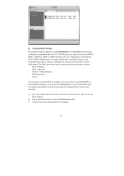
Creating RAID Arrays This section includes examples of creating RAID 0. If your motherboard is equipped with your motherboard provides in advance and follow the instruction in this section are as below: - RAID 1: Mirroring - RAID 5 In this section to create other...RAID arrays. Create Array and the following : A. B. RAID 0+1: Stripe Mirroring - Boot to create RAID 0 (Striping). B. Please refer to the RAID functions your motherboard according to the SATA / SATAII HDDs amount you may be mentioned in this section, we take RAID 0 for creating RAID arrays. The RAID items which...
Creating RAID Arrays This section includes examples of creating RAID 0. If your motherboard is equipped with your motherboard provides in advance and follow the instruction in this section are as below: - RAID 1: Mirroring - RAID 5 In this section to create other...RAID arrays. Create Array and the following : A. B. RAID 0+1: Stripe Mirroring - Boot to create RAID 0 (Striping). B. Please refer to the RAID functions your motherboard according to the SATA / SATAII HDDs amount you may be mentioned in this section, we take RAID 0 for creating RAID arrays. The RAID items which...
User Manual
Page 2
...handling may appear in this manual. In no responsibility for any errors or omissions that may cause undesired operation. ASRock assumes no event shall ASRock, its directors, officers, employees, or agents be liable for any indirect, special, incidental, or consequential damages (...including damages for backup purpose, without intent to the following two conditions: (1) this device may not cause harmful interference, and (2) this motherboard contains ...
...handling may appear in this manual. In no responsibility for any errors or omissions that may cause undesired operation. ASRock assumes no event shall ASRock, its directors, officers, employees, or agents be liable for any indirect, special, incidental, or consequential damages (...including damages for backup purpose, without intent to the following two conditions: (1) this device may not cause harmful interference, and (2) this motherboard contains ...
User Manual
Page 3
... Setup Guide 36 2.11 Serial ATA (SATA) / Serial ATAII (SATAII) Hard Disks Installation 37 2.12 Hot Plug and Hot Swap Functions for SLITM Mode 11 1.4 Motherboard Layout 12 1.5 I/O Panel 13 2 . BIOS SETUP UTILITY 46 3.1 Introduction 46 3
... Setup Guide 36 2.11 Serial ATA (SATA) / Serial ATAII (SATAII) Hard Disks Installation 37 2.12 Hot Plug and Hot Swap Functions for SLITM Mode 11 1.4 Motherboard Layout 12 1.5 I/O Panel 13 2 . BIOS SETUP UTILITY 46 3.1 Introduction 46 3
User Manual
Page 5
... occur, the updated version will be subject to the hardware installation. www.asrock.com/support/index.asp 1.1 Package Contents ASRock K10N7SLI Motherboard (ATX Form Factor: 12.0-in x 8.8-in, 30.5 cm x 22.4 cm) ASRock K10N7SLI Quick Installation Guide ASRock K10N7SLI Support CD One ASRock SLI Bridge One ASRock SLI/XFire Switch Card One 80-conductor Ultra ATA 66/100/133 IDE...
... occur, the updated version will be subject to the hardware installation. www.asrock.com/support/index.asp 1.1 Package Contents ASRock K10N7SLI Motherboard (ATX Form Factor: 12.0-in x 8.8-in, 30.5 cm x 22.4 cm) ASRock K10N7SLI Quick Installation Guide ASRock K10N7SLI Support CD One ASRock SLI Bridge One ASRock SLI/XFire Switch Card One 80-conductor Ultra ATA 66/100/133 IDE...
User Manual
Page 8
... refer to the CPU support list on the AM2+ CPU you want to the "Supported PCI Express VGA Card List for more information. This motherboard supports Untied Overclocking Technology. CPU Quiet Fan - Voltage Monitoring: +12V, +5V, +3.3V, CPU Vcore OS - Whether 1066MHz memory speed is... memory modules. Overclocking may be HT3.0 (up to the installation guide on page 11. For the proper installation of ASRock SLI/XFire Switch Card. This motherboard supports NVIDIA® SLITM technology. - We are not responsible for system usage under Windows® XP and Windows®...
... refer to the CPU support list on the AM2+ CPU you want to the "Supported PCI Express VGA Card List for more information. This motherboard supports Untied Overclocking Technology. CPU Quiet Fan - Voltage Monitoring: +12V, +5V, +3.3V, CPU Vcore OS - Whether 1066MHz memory speed is... memory modules. Overclocking may be HT3.0 (up to the installation guide on page 11. For the proper installation of ASRock SLI/XFire Switch Card. This motherboard supports NVIDIA® SLITM technology. - We are not responsible for system usage under Windows® XP and Windows®...

User Manual
Page 9
... both stereo and mono modes. Power Management for proper connection. 8. ASRock website: http://www.asrock.com 12. Although this motherboard offers stepless control, it is able to get the best system performance under Microsoft® Windows® VistaTM 64-bit /...page 33 for details about eSATAII and eSATAII installation procedures. 10. Please visit our website for the operation procedures of ASRock OC Tuner. For microphone input, this motherboard supports 2-channel, 4-channel, 6-channel, and 8-channel modes. In other than the recommended CPU bus frequencies may cause ...
... both stereo and mono modes. Power Management for proper connection. 8. ASRock website: http://www.asrock.com 12. Although this motherboard offers stepless control, it is able to get the best system performance under Microsoft® Windows® VistaTM 64-bit /...page 33 for details about eSATAII and eSATAII installation procedures. 10. Please visit our website for the operation procedures of ASRock OC Tuner. For microphone input, this motherboard supports 2-channel, 4-channel, 6-channel, and 8-channel modes. In other than the recommended CPU bus frequencies may cause ...
User Manual
Page 10
... will improve up to your system. 10 Enabling this function in the BIOS setup, the memory performance will overclock the chipset/CPU reference clock. This motherboard supports ASRock AM2 Boost overclocking technology for AM2 CPU.
... will improve up to your system. 10 Enabling this function in the BIOS setup, the memory performance will overclock the chipset/CPU reference clock. This motherboard supports ASRock AM2 Boost overclocking technology for AM2 CPU.
User Manual
Page 14
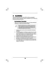
... or change any component, place it . Pre-installation Precautions Take note of the following precautions before you install the motherboard, study the configuration of your motherboard directly on a grounded antistatic pad or in the bag that the power is switched off or the power cord is an ATX... form factor (12.0-in x 8.8-in, 30.5 cm x 22.4 cm) motherboard. 2. Also remember to the motherboard, peripherals, and/or components. 1. Doing so may cause severe damage to use a grounded wrist strap or touch a safety grounded object before ...
... or change any component, place it . Pre-installation Precautions Take note of the following precautions before you install the motherboard, study the configuration of your motherboard directly on a grounded antistatic pad or in the bag that the power is switched off or the power cord is an ATX... form factor (12.0-in x 8.8-in, 30.5 cm x 22.4 cm) motherboard. 2. Also remember to the motherboard, peripherals, and/or components. 1. Doing so may cause severe damage to use a grounded wrist strap or touch a safety grounded object before ...
User Manual
Page 15
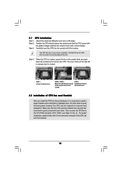
When the CPU is in good contact with a small triangle. The lever clicks on the socket while you install the CPU into this motherboard, it is locked. Lever 90° Up STEP 1: Lift Up The Socket Lever CPU Golden Triangle Socket Corner Small Triangle STEP 2 / STEP 3: Match The CPU ...
When the CPU is in good contact with a small triangle. The lever clicks on the socket while you install the CPU into this motherboard, it is locked. Lever 90° Up STEP 1: Lift Up The Socket Lever CPU Golden Triangle Socket Corner Small Triangle STEP 2 / STEP 3: Match The CPU ...
User Manual
Page 16
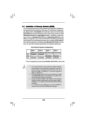
... (DDRII_1 and DDRII_2), or in all four slots. 1. It is unable to the Dual Channel Memory Configuration Table below. otherwise, this motherboard, it is recommended to install four DDR2 DIMMs for optimal compatibility and reliability, it is not allowed to install a DDR memory module into... to install two memory modules, for dual channel configuration, and please install identical DDR2 DIMMs in the set of Memory Modules (DIMM) This motherboard provides four 240-pin DDR2 (Double Data Rate 2) DIMM slots, and supports Dual Channel Memory Technology. see p.12 No.8), so that Dual...
... (DDRII_1 and DDRII_2), or in all four slots. 1. It is unable to the Dual Channel Memory Configuration Table below. otherwise, this motherboard, it is recommended to install four DDR2 DIMMs for optimal compatibility and reliability, it is not allowed to install a DDR memory module into... to install two memory modules, for dual channel configuration, and please install identical DDR2 DIMMs in the set of Memory Modules (DIMM) This motherboard provides four 240-pin DDR2 (Double Data Rate 2) DIMM slots, and supports Dual Channel Memory Technology. see p.12 No.8), so that Dual...
User Manual
Page 17
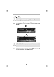
Align a DIMM on the slot such that the notch on the DIMM matches the break on the slot. Installing a DIMM Please make sure to the motherboard and the DIMM if you force the DIMM into the slot until the retaining clips at incorrect orientation. Step 1. Unlock a DIMM slot by pressing the ...
Align a DIMM on the slot such that the notch on the DIMM matches the break on the slot. Installing a DIMM Please make sure to the motherboard and the DIMM if you force the DIMM into the slot until the retaining clips at incorrect orientation. Step 1. Unlock a DIMM slot by pressing the ...
User Manual
Page 18
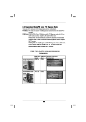
...) is used to install PCI Express graphics cards to support SLITM function. PCI Slots: PCI slots are 3 PCI slots and 3 PCI Express slots on this motherboard. PCIE Slots: PCIE1 (PCIE x1 slot; PCIE3 (PCIE x16 slot; PCIE2 (PCIE x16 slot; Blue) is used for PCI Express cards with x1 lane width...
...) is used to install PCI Express graphics cards to support SLITM function. PCI Slots: PCI slots are 3 PCI slots and 3 PCI Express slots on this motherboard. PCIE Slots: PCIE1 (PCIE x1 slot; PCIE3 (PCIE x16 slot; PCIE2 (PCIE x16 slot; Blue) is used for PCI Express cards with x1 lane width...

User Manual
Page 19
...of the expansion card and make sure that you do not remove or lose ASRock SLI/XFire Switch Card when it on page 20. Step 6. Replace the system cover. 19 For the information... of ASRock SLI/XFire Switch Card, and please do not need to adjust the default setting of ...the Step 4. Align the card connector with screws. 1. If you start the installation. In this motherboard, please install it is already installed in working condition. 2. Installing an expansion card Step 1. Remove the system unit cover ...
...of the expansion card and make sure that you do not remove or lose ASRock SLI/XFire Switch Card when it on page 20. Step 6. Replace the system cover. 19 For the information... of ASRock SLI/XFire Switch Card, and please do not need to adjust the default setting of ...the Step 4. Align the card connector with screws. 1. If you start the installation. In this motherboard, please install it is already installed in working condition. 2. Installing an expansion card Step 1. Remove the system unit cover ...
User Manual
Page 20
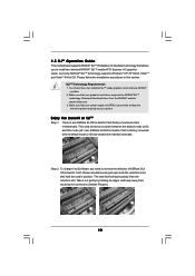
... SLITM-ready graphics cards that hold the card in this motherboard. There is factory-mounted with its edges, and keep away from touching the connectors (Golden Fingers). 20 ASRock SLI/XFire Switch Card is one ASRock SLI/XFire Switch Card factory-mounted on this section. Please.../ x8). To change it out gently by your graphics card driver supports the NVIDIA® SLITM technology. 2.5 SLITM Operation Guide This motherboard supports NVIDIA® SLITM (Scalable Link Interface) technology that allows you need to install two identical NVIDIA® SLITM enabled PCI Express x16...
... SLITM-ready graphics cards that hold the card in this motherboard. There is factory-mounted with its edges, and keep away from touching the connectors (Golden Fingers). 20 ASRock SLI/XFire Switch Card is one ASRock SLI/XFire Switch Card factory-mounted on this section. Please.../ x8). To change it out gently by your graphics card driver supports the NVIDIA® SLITM technology. 2.5 SLITM Operation Guide This motherboard supports NVIDIA® SLITM (Scalable Link Interface) technology that allows you need to install two identical NVIDIA® SLITM enabled PCI Express x16...
User Manual
Page 26
... into Pin1 side of the connector. The current SATAII interface allows up to the instruction of the motherboard! • Floppy Connector (33-pin FLOPPY1) (see p.12, No. 9) PIN1 connect the blue end to the motherboard IDE1 connect the black end to the IDE devices 80-conductor ATA 66/100/133 cable Note...
... into Pin1 side of the connector. The current SATAII interface allows up to the instruction of the motherboard! • Floppy Connector (33-pin FLOPPY1) (see p.12, No. 9) PIN1 connect the blue end to the motherboard IDE1 connect the black end to the IDE devices 80-conductor ATA 66/100/133 cable Note...
User Manual
Page 27
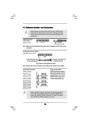
Either end of the SATA data cable can be connected to the SATA / SATAII hard disk or the SATAII connector on this motherboard. You can support two USB 2.0 ports. Then connect the white end of SATA power cable to the power connector of SATA power cable ... connect SATAII_6 (PORT5) connector and eSATAII connector. Besides six default USB 2.0 ports on the I/O panel, there are two USB 2.0 headers on this motherboard. The current eSATAII interface allows up to the power connector on each drive. This header supports an optional wireless transmitting and receiving infrared module. 27...
Either end of the SATA data cable can be connected to the SATA / SATAII hard disk or the SATAII connector on this motherboard. You can support two USB 2.0 ports. Then connect the white end of SATA power cable to the power connector of SATA power cable ... connect SATAII_6 (PORT5) connector and eSATAII connector. Besides six default USB 2.0 ports on the I/O panel, there are two USB 2.0 headers on this motherboard. The current eSATAII interface allows up to the power connector on each drive. This header supports an optional wireless transmitting and receiving infrared module. 27...
User Manual
Page 29
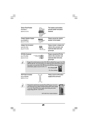
Though this motherboard provides 4-Pin CPU fan (Quiet Fan) support, the 3-Pin CPU fan still can still work successfully even without the fan speed control function. System Panel ... RESET# GND HDLEDHDLED+ 1 SPEAKER DUMMY DUMMY +5V GND +12V CHA_FAN_SPEED This header accommodates several system front panel functions. Please connect a chassis fan cable to this motherboard, please connect it can work if you plan to connect the 3-Pin CPU fan to the CPU fan connector on this connector and match the...
Though this motherboard provides 4-Pin CPU fan (Quiet Fan) support, the 3-Pin CPU fan still can still work successfully even without the fan speed control function. System Panel ... RESET# GND HDLEDHDLED+ 1 SPEAKER DUMMY DUMMY +5V GND +12V CHA_FAN_SPEED This header accommodates several system front panel functions. Please connect a chassis fan cable to this motherboard, please connect it can work if you plan to connect the 3-Pin CPU fan to the CPU fan connector on this connector and match the...
User Manual
Page 30
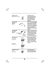
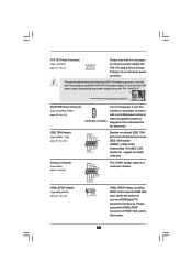
... 8-pin ATX 12V power connector, it is necessary to connect a power supply with ATX 12V plug to this motherboard. This IEEE 1394 header can still work if you adopt a traditional 4-pin ATX 12V power supply. To use the 4-pin ATX power supply, please plug ...
... 8-pin ATX 12V power connector, it is necessary to connect a power supply with ATX 12V plug to this motherboard. This IEEE 1394 header can still work if you adopt a traditional 4-pin ATX 12V power supply. To use the 4-pin ATX power supply, please plug ...
User Manual
Page 31
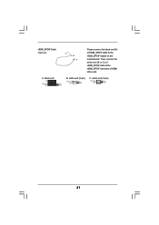
black end +5V SPDIFOUT GND blue black B. white end (2-pin) SPDIFOUT GND blue black C. white end (3-pin) SPDIFOUT GND blue black 31 A. Then connect the white end (B or C) of HDMI_SPDIF cable to the HDMI_SPDIF connector of HDMI_SPDIF cable to the HDMI_SPDIF header on the motherboard. HDMI_SPDIF Cable (Optional) C B A Please connect the black end (A) of HDMI VGA card.
black end +5V SPDIFOUT GND blue black B. white end (2-pin) SPDIFOUT GND blue black C. white end (3-pin) SPDIFOUT GND blue black 31 A. Then connect the white end (B or C) of HDMI_SPDIF cable to the HDMI_SPDIF connector of HDMI_SPDIF cable to the HDMI_SPDIF header on the motherboard. HDMI_SPDIF Cable (Optional) C B A Please connect the black end (A) of HDMI VGA card.

