
RAID Installation Guide
Page 5
... to the OS you install. 1.3.1 Installing Windows® XP / XP 64-bit With RAID Functions If you want to enable Hot Plug function on eSATAII ports but you will start to [RAID]. 5 Set the "SATA Operation Mode" option to boot your system. IDE Configuration. C. Exit Reboot system now Press any key. Insert the ASRock Support CD into your optical drive to [IDE]. Please select CD-ROM as the boot device. Generate RAID Driver diskette for WindowsXP/XP64...
... to the OS you install. 1.3.1 Installing Windows® XP / XP 64-bit With RAID Functions If you want to enable Hot Plug function on eSATAII ports but you will start to [RAID]. 5 Set the "SATA Operation Mode" option to boot your system. IDE Configuration. C. Exit Reboot system now Press any key. Insert the ASRock Support CD into your optical drive to [IDE]. Please select CD-ROM as the boot device. Generate RAID Driver diskette for WindowsXP/XP64...
RAID Installation Guide
Page 7
.... STEP 1: Set Up BIOS. Before you start to configure RAID function, you want to install Windows® VistaTM / Windows® VistaTM 64-bit on the bottom to the BIOS RAID installation guide part of the document in the following path in the Support CD: .. \ RAID Installation Guide STEP 3: Install Windows® VistaTM / VistaTM 64-bit OS on your SATA / SATAII HDDs with RAID functions, please follow the instruction to [RAID] in BIOS first. Enter BIOS SETUP UTILITY Advanced screen IDE Configuration. NVIDIA® RAID drivers are...
.... STEP 1: Set Up BIOS. Before you start to configure RAID function, you want to install Windows® VistaTM / Windows® VistaTM 64-bit on the bottom to the BIOS RAID installation guide part of the document in the following path in the Support CD: .. \ RAID Installation Guide STEP 3: Install Windows® VistaTM / VistaTM 64-bit OS on your SATA / SATAII HDDs with RAID functions, please follow the instruction to [RAID] in BIOS first. Enter BIOS SETUP UTILITY Advanced screen IDE Configuration. NVIDIA® RAID drivers are...
RAID Installation Guide
Page 11
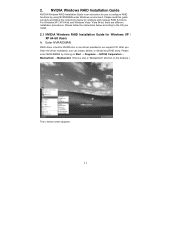
Please enter NVRAIDMAN by using NVIDIAMAN under Windows environment. Please follow the instructions below screen appears. 11 Please read this guide carefully and follow the instructions below according to configure and manage RAID functions. For Windows XP / XP 64-bit and Windows Vista / Vista 64-bit, there are different installation procedures. After you finish the driver installation, you to configure RAID functions by clicking on the desktop.) Then, below to...
Please enter NVRAIDMAN by using NVIDIAMAN under Windows environment. Please follow the instructions below screen appears. 11 Please read this guide carefully and follow the instructions below according to configure and manage RAID functions. For Windows XP / XP 64-bit and Windows Vista / Vista 64-bit, there are different installation procedures. After you finish the driver installation, you to configure RAID functions by clicking on the desktop.) Then, below to...
User Manual
Page 3
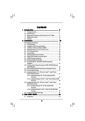
...16.2 Installing Windows® VistaTM / VistaTM 64-bit With RAID Functions 44 2.17 Untied Overclocking Technology 45 3 . Contents 1 . BIOS SETUP UTILITY 46 3.1 Introduction 46 3 Installation 14 Pre-installation Precautions 14 2.1 CPU Installation 15 2.2 Installation of CPU Fan and Heatsink 15 2.3 Installation of Memory Modules (DIMM 16 2.4 Expansion Slots (PCI and PCI Express slots 18 2.5 SLITM Operation Guide 20 2.6 Jumpers Setup 25 2.7 Onboard Headers and Connectors 26 2.8 HDMI_SPDIF Header Connection Guide 32 2.9 eSATAII Interface Introduction 33 2.10 SATAII Hard Disk Setup...
...16.2 Installing Windows® VistaTM / VistaTM 64-bit With RAID Functions 44 2.17 Untied Overclocking Technology 45 3 . Contents 1 . BIOS SETUP UTILITY 46 3.1 Introduction 46 3 Installation 14 Pre-installation Precautions 14 2.1 CPU Installation 15 2.2 Installation of CPU Fan and Heatsink 15 2.3 Installation of Memory Modules (DIMM 16 2.4 Expansion Slots (PCI and PCI Express slots 18 2.5 SLITM Operation Guide 20 2.6 Jumpers Setup 25 2.7 Onboard Headers and Connectors 26 2.8 HDMI_SPDIF Header Connection Guide 32 2.9 eSATAII Interface Introduction 33 2.10 SATAII Hard Disk Setup...

User Manual
Page 9
... also connect SATA hard disk to SATAII connector directly. 9. Please read the "SATAII Hard Disk Setup Guide" on the motherboard functions properly and unplug the power cord, then plug it is able to perform over-clocking. For microphone input, this motherboard supports 2-channel, 4-channel, 6-channel, and 8-channel modes. It is a user-friendly ASRock overclocking tool which allows you resume the system, please check if the CPU fan on page 36 to adjust your hardware devices to...
... also connect SATA hard disk to SATAII connector directly. 9. Please read the "SATAII Hard Disk Setup Guide" on the motherboard functions properly and unplug the power cord, then plug it is able to perform over-clocking. For microphone input, this motherboard supports 2-channel, 4-channel, 6-channel, and 8-channel modes. It is a user-friendly ASRock overclocking tool which allows you resume the system, please check if the CPU fan on page 36 to adjust your hardware devices to...
User Manual
Page 32
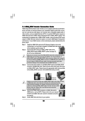
... this motherboard. Install HDMI VGA card driver to the same pin definition. A complete HDMI system requires a HDMI VGA card and a HDMI ready motherboard with a HDMI_SPDIF header, which provides an interface between any compatible digital audio/video source, such as a set-top box, DVD player, A/V receiver and a compatible digital audio or video monitor, such as HDTV. Please refer to the fan connector of HDMI VGA card vendor. Incorrect connection may be damaged. Please choose the appropriate white end according to HDMI device...
... this motherboard. Install HDMI VGA card driver to the same pin definition. A complete HDMI system requires a HDMI VGA card and a HDMI ready motherboard with a HDMI_SPDIF header, which provides an interface between any compatible digital audio/video source, such as a set-top box, DVD player, A/V receiver and a compatible digital audio or video monitor, such as HDTV. Please refer to the fan connector of HDMI VGA card vendor. Incorrect connection may be damaged. Please choose the appropriate white end according to HDMI device...
User Manual
Page 33
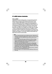
... the high speed data transfer rate up to 3.0Gb/s, and the convenient mobility like USB. This motherboard supports eSATAII interface, the external SATAII specification. If you set "SATA Operation Mode" option in the near future, eSATAII will replace USB 2.0 and IEEE 1394 to RAID mode. 4. If you may affect the Hot Plug function that enables you want to use the eSATAII HDD as a RAID disk, please set "SATA Operation Mode" option in BIOS setup to be...
... the high speed data transfer rate up to 3.0Gb/s, and the convenient mobility like USB. This motherboard supports eSATAII interface, the external SATAII specification. If you set "SATA Operation Mode" option in the near future, eSATAII will replace USB 2.0 and IEEE 1394 to RAID mode. 4. If you may affect the Hot Plug function that enables you want to use the eSATAII HDD as a RAID disk, please set "SATA Operation Mode" option in BIOS setup to be...
User Manual
Page 36
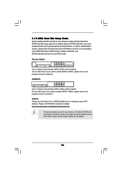
... SATAII hard disk products of SATAII hard disks may not be enabled. Western Digital 7531 8642 If pin 5 and pin 6 are shorted, SATA 1.5Gb/s will be at SATAII mode. Some default setting of different vendors, the jumper pin setting methods may fail to SATAII mode in advance; Please visit HITACHI's website for details: http://www.hitachigst.com/hdd/support/download.htm The above examples are just for the updates. 36...
... SATAII hard disk products of SATAII hard disks may not be enabled. Western Digital 7531 8642 If pin 5 and pin 6 are shorted, SATA 1.5Gb/s will be at SATAII mode. Some default setting of different vendors, the jumper pin setting methods may fail to SATAII mode in advance; Please visit HITACHI's website for details: http://www.hitachigst.com/hdd/support/download.htm The above examples are just for the updates. 36...
User Manual
Page 41
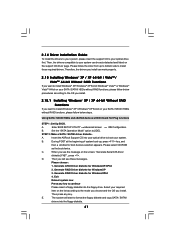
..., Please choose: 1. Enter BIOS SETUP UTILITY Advanced screen IDE Configuration. Insert the ASRock Support CD into the floppy drive. C. D. Generate RAID Driver diskette for WindowsXP/XP64 2. Select your required item on the support CD driver page. The system will see the message on your SATA / SATAII HDDs without RAID functions, please follow below procedures according to the OS you install. 2.15.1 Installing Windows® XP / XP 64-bit Without RAID Functions If you...
..., Please choose: 1. Enter BIOS SETUP UTILITY Advanced screen IDE Configuration. Insert the ASRock Support CD into the floppy drive. C. D. Generate RAID Driver diskette for WindowsXP/XP64 2. Select your required item on the support CD driver page. The system will see the message on your SATA / SATAII HDDs without RAID functions, please follow below procedures according to the OS you install. 2.15.1 Installing Windows® XP / XP 64-bit Without RAID Functions If you...
User Manual
Page 44
... rebuild) RAID functions on IDE HDDs and want to the BIOS RAID installation guide part of the document in the following path in the Support CD: .. \ RAID Installation Guide 44 Please refer to install Windows? Insert the Windows® VistaTM / Windows® VistaTM 64-bit optical disk into your system. A. A. " page, please insert the ASRock Support CD into the optical drive to [RAID]. Then, please set RAID configuration. NOTE. NVIDIA RAID Driver (required) B. B. Set the "SATA Operation Mode" option to boot your...
... rebuild) RAID functions on IDE HDDs and want to the BIOS RAID installation guide part of the document in the following path in the Support CD: .. \ RAID Installation Guide 44 Please refer to install Windows? Insert the Windows® VistaTM / Windows® VistaTM 64-bit optical disk into your system. A. A. " page, please insert the ASRock Support CD into the optical drive to [RAID]. Then, please set RAID configuration. NOTE. NVIDIA RAID Driver (required) B. B. Set the "SATA Operation Mode" option to boot your...
User Manual
Page 54
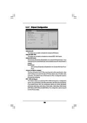
...BIOS SETUP UTILITY Advanced Chipset Settings Onboard LAN Onboard 1394 OnBoard HD Audio Front Panel Primary Graphics Adapter CPU - Primary Graphics Adapter This item will be disabled when PCI Sound Card is [PCI]. If you select [Auto], the onboard HD Audio will switch the PCI Bus scanning order while searching for video card. The default value of multiple video controllers. NB Link Width DRAM Voltage Chipset Core Voltage HT Voltage [Enabled] [Enabled] [Auto] [Auto] [PCI] [Auto] [Auto] [Auto] [Auto] [Auto] To set DRAM Voltage. +F1 F9 F10 ESC Select Screen Select Item Change Option...
...BIOS SETUP UTILITY Advanced Chipset Settings Onboard LAN Onboard 1394 OnBoard HD Audio Front Panel Primary Graphics Adapter CPU - Primary Graphics Adapter This item will be disabled when PCI Sound Card is [PCI]. If you select [Auto], the onboard HD Audio will switch the PCI Bus scanning order while searching for video card. The default value of multiple video controllers. NB Link Width DRAM Voltage Chipset Core Voltage HT Voltage [Enabled] [Enabled] [Auto] [Auto] [PCI] [Auto] [Auto] [Auto] [Auto] [Auto] To set DRAM Voltage. +F1 F9 F10 ESC Select Screen Select Item Change Option...
User Manual
Page 57
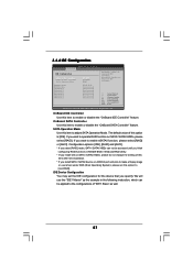
... enable or disable the "OnBoard IDE Controller" feature. The default value of this option is [IDE]. We will use Ghost under DOS (Disk Operating System), please set the IDE configuration for the device that you want to operate RAID function on eSATAII port and plan to make a floppy image or use the "IDE1 Master" as the example in NVIDIA BIOS / Windows RAID Utility. * If you install OS on SATA / SATAII HDDs, please do not change the setting...
... enable or disable the "OnBoard IDE Controller" feature. The default value of this option is [IDE]. We will use Ghost under DOS (Disk Operating System), please set the IDE configuration for the device that you want to operate RAID function on eSATAII port and plan to make a floppy image or use the "IDE1 Master" as the example in NVIDIA BIOS / Windows RAID Utility. * If you install OS on SATA / SATAII HDDs, please do not change the setting...
User Manual
Page 59
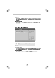
... this item to enable 32-bit access to maximize the IDE hard disk data transfer rate. 3.4.5 PCIPnP Configuration BIOS SETUP UTILITY Advanced Advanced PCI / PnP Settings PCI Latency Timer PCI IDE BusMaster [32] [Enabled] Value in units of PCI clocks for PCI device latency timer register. +F1 F9 F10 ESC Select Screen Select Item Change Option General Help Load Defaults Save and Exit Exit v02.54 (C) Copyright 1985-2003, American Megatrends, Inc. PCI Latency Timer The...
... this item to enable 32-bit access to maximize the IDE hard disk data transfer rate. 3.4.5 PCIPnP Configuration BIOS SETUP UTILITY Advanced Advanced PCI / PnP Settings PCI Latency Timer PCI IDE BusMaster [32] [Enabled] Value in units of PCI clocks for PCI device latency timer register. +F1 F9 F10 ESC Select Screen Select Item Change Option General Help Load Defaults Save and Exit Exit v02.54 (C) Copyright 1985-2003, American Megatrends, Inc. PCI Latency Timer The...
User Manual
Page 60
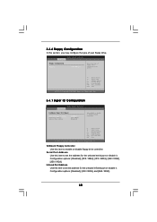
... Port Address Use this item to set the address for the onboard infrared port or disable it . 3.4.6 Floppy Configuration In this section, you may configure the type of floppy drive connected to the system. +F1 F9 F10 ESC Select Screen Select Item Change Option General Help Load Defaults Save and Exit Exit v02.54 (C) Copyright 1985-2003, American Megatrends, Inc. 3.4.7 Super IO Configuration BIOS SETUP UTILITY Advanced Configure Super IO Chipset OnBoard Floppy Controller Serial Port Address Infrared Port Address [Enabled...
... Port Address Use this item to set the address for the onboard infrared port or disable it . 3.4.6 Floppy Configuration In this section, you may configure the type of floppy drive connected to the system. +F1 F9 F10 ESC Select Screen Select Item Change Option General Help Load Defaults Save and Exit Exit v02.54 (C) Copyright 1985-2003, American Megatrends, Inc. 3.4.7 Super IO Configuration BIOS SETUP UTILITY Advanced Configure Super IO Chipset OnBoard Floppy Controller Serial Port Address Infrared Port Address [Enabled...
User Manual
Page 61
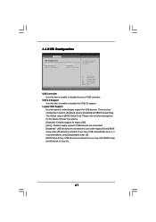
...USB Support Use this item to enter OS. [BIOS Setup Only] - USB 2.0 Support Use this item to use of these four options: [Enabled] - The default value is [BIOS Setup Only]. Enables support for the details of USB controller. USB devices are not allowed to enable or disable the USB 2.0 support. 3.4.8 USB Configuration BIOS SETUP UTILITY Advanced USB Configuration USB Controller USB 2.0 Support Legacy USB Support [Enabled] [Enabled] [BIOS Setup Only] To enable or disable the onboard USB controllers. +F1 F9 F10 ESC Select Screen Select Item Change Option General Help Load Defaults...
...USB Support Use this item to enter OS. [BIOS Setup Only] - USB 2.0 Support Use this item to use of these four options: [Enabled] - The default value is [BIOS Setup Only]. Enables support for the details of USB controller. USB devices are not allowed to enable or disable the USB 2.0 support. 3.4.8 USB Configuration BIOS SETUP UTILITY Advanced USB Configuration USB Controller USB 2.0 Support Legacy USB Support [Enabled] [Enabled] [BIOS Setup Only] To enable or disable the onboard USB controllers. +F1 F9 F10 ESC Select Screen Select Item Change Option General Help Load Defaults...
User Manual
Page 64
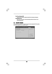
BIOS SETUP UTILITY Main Smart Advanced H/W Monitor Boot Security Exit Security Settings Supervisor Password : Not Installed User Password : Not Installed Change Supervisor Password Change User Password Install or Change the password. Select Screen Select Item Enter Change F1 General Help F9 Load Defaults F10 Save and Exit ESC Exit v02.54 (C) Copyright 1985-2005, American Megatrends, Inc. 64 Boot Up Num-Lock If this item is set or change the supervisor/user password for the system. For the user password, you may also clear it...
BIOS SETUP UTILITY Main Smart Advanced H/W Monitor Boot Security Exit Security Settings Supervisor Password : Not Installed User Password : Not Installed Change Supervisor Password Change User Password Install or Change the password. Select Screen Select Item Enter Change F1 General Help F9 Load Defaults F10 Save and Exit ESC Exit v02.54 (C) Copyright 1985-2005, American Megatrends, Inc. 64 Boot Up Num-Lock If this item is set or change the supervisor/user password for the system. For the user password, you may also clear it...
User Manual
Page 66
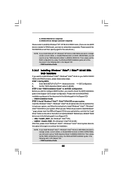
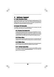
... the motherboard contains necessary drivers and useful utilities that the motherboard supports. Software Support 4.1 Install Operating System This motherboard supports various Microsoft® Windows® operating systems: XP / XP Media Center / XP 64-bit / VistaTM / VistaTM 64-bit. Because motherboard settings and hardware options vary, use the setup procedures in the Support CD to visit ASRock's website at http://www.asrock.com; If the Main Menu did not appear automatically, locate and double click on a specific...
... the motherboard contains necessary drivers and useful utilities that the motherboard supports. Software Support 4.1 Install Operating System This motherboard supports various Microsoft® Windows® operating systems: XP / XP Media Center / XP 64-bit / VistaTM / VistaTM 64-bit. Because motherboard settings and hardware options vary, use the setup procedures in the Support CD to visit ASRock's website at http://www.asrock.com; If the Main Menu did not appear automatically, locate and double click on a specific...
Quick Installation Guide
Page 2
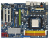
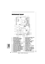
... Panel Header (PANEL1, Orange) 2 ATX Power Connector (ATXPWR1) 22 Front Panel IEEE 1394 Header 3 ATX 12V Power Connector (ATX12V1) (FRONT_1394, Red) 4 CPU Fan Connector (CPU_FAN1) 23 Chassis Speaker Header 5 AM2 940-Pin CPU Socket (SPEAKER 1, Purple) 6 CPU Heatsink Retention Module 24 Chassis Fan Connector (CHA_FAN1) 7 2 x 240-pin DDR2 DIMM Slots 25 Floppy Connector (FLOPPY1) (Dual Channel A: DDRII_1, DDRII_2; Orange) (HDMI_SPDIF1, Yellow) 9 Primary IDE Connector (IDE1, Blue) 28 Front Panel Audio Header 10 NVIDIA nForce 740a SLI Chipset (HD_AUDIO1, Lime) 11 Clear CMOS Jumper...
... Panel Header (PANEL1, Orange) 2 ATX Power Connector (ATXPWR1) 22 Front Panel IEEE 1394 Header 3 ATX 12V Power Connector (ATX12V1) (FRONT_1394, Red) 4 CPU Fan Connector (CPU_FAN1) 23 Chassis Speaker Header 5 AM2 940-Pin CPU Socket (SPEAKER 1, Purple) 6 CPU Heatsink Retention Module 24 Chassis Fan Connector (CHA_FAN1) 7 2 x 240-pin DDR2 DIMM Slots 25 Floppy Connector (FLOPPY1) (Dual Channel A: DDRII_1, DDRII_2; Orange) (HDMI_SPDIF1, Yellow) 9 Primary IDE Connector (IDE1, Blue) 28 Front Panel Audio Header 10 NVIDIA nForce 740a SLI Chipset (HD_AUDIO1, Lime) 11 Clear CMOS Jumper...
Quick Installation Guide
Page 8
... on page 28 for USB 2.0 works fine under Windows® environment. 7. Although this motherboard offers stepless control, it is a user-friendly ASRock overclocking tool which allows you install the PC system. 8 ASRock K10N7SLI Motherboard English It is not recommended to SATAII mode. In other than the recommended CPU bus frequencies may cause the instability of Intelligent Energy Saver. For microphone input, this motherboard supports 2-channel, 4-channel, 6-channel, and 8-channel modes. To improve heat...
... on page 28 for USB 2.0 works fine under Windows® environment. 7. Although this motherboard offers stepless control, it is a user-friendly ASRock overclocking tool which allows you install the PC system. 8 ASRock K10N7SLI Motherboard English It is not recommended to SATAII mode. In other than the recommended CPU bus frequencies may cause the instability of Intelligent Energy Saver. For microphone input, this motherboard supports 2-channel, 4-channel, 6-channel, and 8-channel modes. To improve heat...
Quick Installation Guide
Page 32
... the motherboard contains necessary drivers and useful utilities that will display the Main Menu automatically if "AUTORUN" is designed to the User Manual (PDF file) contained in the Support CD. 4. It will enhance motherboard features. EXE" from the "BIN" folder in your CD-ROM drive. The BIOS Setup program is enabled in the Support CD to enter BIOS Setup utility; For the detailed information about BIOS Setup, please refer to be user-friendly. Software Support CD information This motherboard supports...
... the motherboard contains necessary drivers and useful utilities that will display the Main Menu automatically if "AUTORUN" is designed to the User Manual (PDF file) contained in the Support CD. 4. It will enhance motherboard features. EXE" from the "BIN" folder in your CD-ROM drive. The BIOS Setup program is enabled in the Support CD to enter BIOS Setup utility; For the detailed information about BIOS Setup, please refer to be user-friendly. Software Support CD information This motherboard supports...


