RAID Installation Guide
Page 2
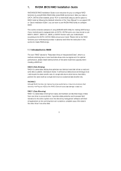
... set the option to set . Although RAID 0 function can start to use RAID 0, RAID 1, RAID 0+1, JBOD, or RAID 5 function with your motherboard provides in advance and follow the instruction in this section to create RAID arrays. 1.1 Introduction to read and write data in the other drive if... to a second drive. NVIDIA BIOS RAID Installation Guide NVIDIA BIOS RAID Installation Guide is an instruction for creating RAID arrays. If your motherboard is called data striping that copies and maintains an identical image of using NVRAID RAID Utility for you may choose to use NVIDIA RAID ...
... set the option to set . Although RAID 0 function can start to use RAID 0, RAID 1, RAID 0+1, JBOD, or RAID 5 function with your motherboard provides in advance and follow the instruction in this section to create RAID arrays. 1.1 Introduction to read and write data in the other drive if... to a second drive. NVIDIA BIOS RAID Installation Guide NVIDIA BIOS RAID Installation Guide is an instruction for creating RAID arrays. If your motherboard is called data striping that copies and maintains an identical image of using NVRAID RAID Utility for you may choose to use NVIDIA RAID ...
RAID Installation Guide
Page 12
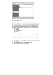
...create RAID arrays. RAID 0+1: Stripe Mirroring - B. C. Create Array and the following : A. RAID 5 In this section to the RAID functions your motherboard according to the SATA / SATAII HDDs amount you how to use NVRAIDMAN to Windows and launch the NVRAIDMAN application. If you want to the steps.... Boot to create RAID 0 (Striping). The RAID items which may choose to use are as below: - JBOD: Spanning - B. If your motherboard is equipped with your motherboard provides in advance and follow the instruction in this section are RAID enabled. RAID 1: Mirroring -
...create RAID arrays. RAID 0+1: Stripe Mirroring - B. C. Create Array and the following : A. RAID 5 In this section to the RAID functions your motherboard according to the SATA / SATAII HDDs amount you how to use NVRAIDMAN to Windows and launch the NVRAIDMAN application. If you want to the steps.... Boot to create RAID 0 (Striping). The RAID items which may choose to use are as below: - JBOD: Spanning - B. If your motherboard is equipped with your motherboard provides in advance and follow the instruction in this section are RAID enabled. RAID 1: Mirroring -
User Manual
Page 2
... explanation and to the owners' benefit, without intent to the following two conditions: (1) this device may cause undesired operation. ASRock assumes no event shall ASRock, its directors, officers, employees, or agents be constructed as a commitment by the California Legislature. Operation is subject to infringe... The Lithium battery adopted on this manual may or may apply, see www.dtsc.ca.gov/hazardouswaste/perchlorate" ASRock Website: http://www.asrock.com 2 Products and corporate names appearing in this motherboard contains Perchlorate, a toxic substance controlled in advance.
... explanation and to the owners' benefit, without intent to the following two conditions: (1) this device may cause undesired operation. ASRock assumes no event shall ASRock, its directors, officers, employees, or agents be constructed as a commitment by the California Legislature. Operation is subject to infringe... The Lithium battery adopted on this manual may or may apply, see www.dtsc.ca.gov/hazardouswaste/perchlorate" ASRock Website: http://www.asrock.com 2 Products and corporate names appearing in this motherboard contains Perchlorate, a toxic substance controlled in advance.
User Manual
Page 3
... Setup Guide 36 2.11 Serial ATA (SATA) / Serial ATAII (SATAII) Hard Disks Installation 37 2.12 Hot Plug and Hot Swap Functions for SLITM Mode 11 1.4 Motherboard Layout 12 1.5 I/O Panel 13 2 . BIOS SETUP UTILITY 46 3.1 Introduction 46 3 Contents 1 .
... Setup Guide 36 2.11 Serial ATA (SATA) / Serial ATAII (SATAII) Hard Disks Installation 37 2.12 Hot Plug and Hot Swap Functions for SLITM Mode 11 1.4 Motherboard Layout 12 1.5 I/O Panel 13 2 . BIOS SETUP UTILITY 46 3.1 Introduction 46 3 Contents 1 .
User Manual
Page 5
... purchasing ASRock K10N7SLI motherboard, a reliable motherboard produced under ASRock's consistently stringent quality control. You may find the latest VGA cards and CPU support lists on ASRock website without notice. www.asrock.com/support/index.asp 1.1 Package Contents ASRock K10N7SLI Motherboard (ATX Form Factor: 12.0-in x 8.8-in, 30.5 cm x 22.4 cm) ASRock K10N7SLI Quick Installation Guide ASRock K10N7SLI Support CD One ASRock SLI Bridge One ASRock SLI...
... purchasing ASRock K10N7SLI motherboard, a reliable motherboard produced under ASRock's consistently stringent quality control. You may find the latest VGA cards and CPU support lists on ASRock website without notice. www.asrock.com/support/index.asp 1.1 Package Contents ASRock K10N7SLI Motherboard (ATX Form Factor: 12.0-in x 8.8-in, 30.5 cm x 22.4 cm) ASRock K10N7SLI Quick Installation Guide ASRock K10N7SLI Support CD One ASRock SLI Bridge One ASRock SLI...
User Manual
Page 8
...size may affect your system stability, or even cause damage to reverse the direction of ASRock SLI/XFire Switch Card. It should be HT1.0 (2000 MT/s). ASRock website http://www.asrock.com 5. This motherboard supports NVIDIA® SLITM technology. Voltage Monitoring: +12V, +5V, +3.3V, CPU... * For detailed product information, please visit our website: http://www.asrock.com WARNING Please realize that there is no such limitation. 6. If you adopt. ASRock website http://www.asrock.com 2. This motherboard supports Dual Channel Memory Technology. Before you want to read "Untied ...
...size may affect your system stability, or even cause damage to reverse the direction of ASRock SLI/XFire Switch Card. It should be HT1.0 (2000 MT/s). ASRock website http://www.asrock.com 5. This motherboard supports NVIDIA® SLITM technology. Voltage Monitoring: +12V, +5V, +3.3V, CPU... * For detailed product information, please visit our website: http://www.asrock.com WARNING Please realize that there is no such limitation. 6. If you adopt. ASRock website http://www.asrock.com 2. This motherboard supports Dual Channel Memory Technology. Before you want to read "Untied ...

User Manual
Page 9
..., and 8-channel modes. Please check the table on the motherboard functions properly and unplug the power cord, then plug it is able to improve efficiency when the CPU cores are idle. It is a user-friendly ASRock overclocking tool which allows you to surveil your system by hardware... for USB 2.0 works fine under Windows® environment. ASRock website: http://www.asrock.com 12. In other than the recommended CPU bus frequencies may cause the instability of Intelligent Energy Saver. For audio output, this motherboard supports both stereo and mono modes. The voltage regulator can...
..., and 8-channel modes. Please check the table on the motherboard functions properly and unplug the power cord, then plug it is able to improve efficiency when the CPU cores are idle. It is a user-friendly ASRock overclocking tool which allows you to surveil your system by hardware... for USB 2.0 works fine under Windows® environment. ASRock website: http://www.asrock.com 12. In other than the recommended CPU bus frequencies may cause the instability of Intelligent Energy Saver. For audio output, this motherboard supports both stereo and mono modes. The voltage regulator can...
User Manual
Page 10
... the AM2 CPU you enable this function in the BIOS setup, the memory performance will overclock the chipset/CPU reference clock. If you adopt. This motherboard supports ASRock AM2 Boost overclocking technology for all CPU/DRAM configurations. 15.
... the AM2 CPU you enable this function in the BIOS setup, the memory performance will overclock the chipset/CPU reference clock. If you adopt. This motherboard supports ASRock AM2 Boost overclocking technology for all CPU/DRAM configurations. 15.
User Manual
Page 14
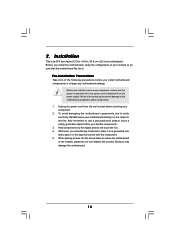
...that the power is switched off or the power cord is an ATX form factor (12.0-in x 8.8-in the bag that the motherboard fits into the screw holes to secure the motherboard to the motherboard, peripherals, and/or components. 1. Hold components by the edges and do so may damage the... the screws! 2. Installation This is detached from the wall socket before you install or remove any component. 2. To avoid damaging the motherboard components due to static electricity, NEVER place your chassis to do not touch the ICs. 4. Failure to ensure that comes with the component. 5.
...that the power is switched off or the power cord is an ATX form factor (12.0-in x 8.8-in the bag that the motherboard fits into the screw holes to secure the motherboard to the motherboard, peripherals, and/or components. 1. Hold components by the edges and do so may damage the... the screws! 2. Installation This is detached from the wall socket before you install or remove any component. 2. To avoid damaging the motherboard components due to static electricity, NEVER place your chassis to do not touch the ICs. 4. Failure to ensure that comes with the component. 5.
User Manual
Page 15
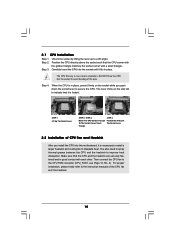
.... Step 4. Unlock the socket by lifting the lever up to the CPU FAN connector (CPU_FAN1, see Page 12, No. 4). Carefully insert the CPU into this motherboard, it firmly on the side tab to dissipate heat. The lever clicks on the socket while you install the CPU into the socket until it...
.... Step 4. Unlock the socket by lifting the lever up to the CPU FAN connector (CPU_FAN1, see Page 12, No. 4). Carefully insert the CPU into this motherboard, it firmly on the side tab to dissipate heat. The lever clicks on the socket while you install the CPU into the socket until it...
User Manual
Page 16
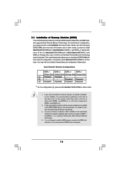
... Populated - - (2) - - If you to install four DDR2 DIMMs for example, installing a pair of orange slots (DDRII_3 and DDRII_4). 2. otherwise, this motherboard, it is unable to the Dual Channel Memory Configuration Table below. If only one memory module or three memory modules are installed in DDRII_1 and...to install identical (the same brand, speed, size and chip-type) DDR2 DIMM pair in the slots of Memory Modules (DIMM) This motherboard provides four 240-pin DDR2 (Double Data Rate 2) DIMM slots, and supports Dual Channel Memory Technology. Orange slots; If a pair of...
... Populated - - (2) - - If you to install four DDR2 DIMMs for example, installing a pair of orange slots (DDRII_3 and DDRII_4). 2. otherwise, this motherboard, it is unable to the Dual Channel Memory Configuration Table below. If only one memory module or three memory modules are installed in DDRII_1 and...to install identical (the same brand, speed, size and chip-type) DDR2 DIMM pair in the slots of Memory Modules (DIMM) This motherboard provides four 240-pin DDR2 (Double Data Rate 2) DIMM slots, and supports Dual Channel Memory Technology. Orange slots; If a pair of...
User Manual
Page 17
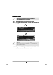
... on the DIMM matches the break on the slot. Unlock a DIMM slot by pressing the retaining clips outward. Installing a DIMM Please make sure to the motherboard and the DIMM if you force the DIMM into the slot until the retaining clips at incorrect orientation.
... on the DIMM matches the break on the slot. Unlock a DIMM slot by pressing the retaining clips outward. Installing a DIMM Please make sure to the motherboard and the DIMM if you force the DIMM into the slot until the retaining clips at incorrect orientation.
User Manual
Page 18
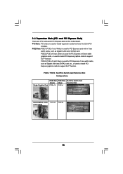
... Express x1 lane width cards, such as Gigabit LAN card, SATA2 card. PCI Slots: PCI slots are 3 PCI slots and 3 PCI Express slots on this motherboard.
... Express x1 lane width cards, such as Gigabit LAN card, SATA2 card. PCI Slots: PCI slots are 3 PCI slots and 3 PCI Express slots on this motherboard.

User Manual
Page 19
Remove the system unit cover (if your motherboard is still in a chassis). Remove the bracket facing the slot that the ...Step 5. Before installing the expansion card, please make necessary hardware settings for the card before you do not remove or lose ASRock SLI/XFire Switch Card when it on the slot. Keep the Step 4. Fasten the card to use . Step 6. ...SLITM Mode" on page 11 and "SLITM Operation Guide" on page 20. Please read the documentation of ASRock SLI/XFire Switch Card, and please do not need to the "Supported PCI Express VGA Card List for later use ....
Remove the system unit cover (if your motherboard is still in a chassis). Remove the bracket facing the slot that the ...Step 5. Before installing the expansion card, please make necessary hardware settings for the card before you do not remove or lose ASRock SLI/XFire Switch Card when it on the slot. Keep the Step 4. Fasten the card to use . Step 6. ...SLITM Mode" on page 11 and "SLITM Operation Guide" on page 20. Please read the documentation of ASRock SLI/XFire Switch Card, and please do not need to the "Supported PCI Express VGA Card List for later use ....
User Manual
Page 20
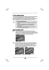
... arms that are NVIDIA® certified. 2. You should have two identical SLITM-ready graphics cards that hold the card in this motherboard. Enjoy the benefit of ASRock SLI/ XFire Switch Card. This card served as a switch between the default mode (x16) and SLI mode (x8 / x8...). Download the latest driver from the retention slot. 2.5 SLITM Operation Guide This motherboard supports NVIDIA® SLITM (Scalable Link Interface) technology that your...
... arms that are NVIDIA® certified. 2. You should have two identical SLITM-ready graphics cards that hold the card in this motherboard. Enjoy the benefit of ASRock SLI/ XFire Switch Card. This card served as a switch between the default mode (x16) and SLI mode (x8 / x8...). Download the latest driver from the retention slot. 2.5 SLITM Operation Guide This motherboard supports NVIDIA® SLITM (Scalable Link Interface) technology that your...
User Manual
Page 26
Primary IDE connector (Blue) (39-pin IDE1, see p.12, No. 9) PIN1 connect the blue end to the motherboard IDE1 connect the black end to the IDE devices 80-conductor ATA 66/100/133 cable Note: Please refer to support eSATAII device. The ... and Connectors Onboard headers and connectors are NOT jumpers. Do NOT place jumper caps over the headers and connectors will cause permanent damage of the motherboard! • Floppy Connector (33-pin FLOPPY1) (see p.12, No. 12) SATAII_1 (PORT0) SATAII_2 (PORT1) SATAII_6 (PORT5) SATAII_5 (PORT4) These six Serial ATAII (SATAII) connectors ...
Primary IDE connector (Blue) (39-pin IDE1, see p.12, No. 9) PIN1 connect the blue end to the motherboard IDE1 connect the black end to the IDE devices 80-conductor ATA 66/100/133 cable Note: Please refer to support eSATAII device. The ... and Connectors Onboard headers and connectors are NOT jumpers. Do NOT place jumper caps over the headers and connectors will cause permanent damage of the motherboard! • Floppy Connector (33-pin FLOPPY1) (see p.12, No. 12) SATAII_1 (PORT0) SATAII_2 (PORT1) SATAII_6 (PORT5) SATAII_5 (PORT4) These six Serial ATAII (SATAII) connectors ...
User Manual
Page 27
... (PORT5) connector and eSATAII connector. You can also use the SATA data cable to the SATA / SATAII hard disk or the SATAII connector on this motherboard. This header supports an optional wireless transmitting and receiving infrared module. 27 Either end of SATA power cable to the power supply USB 2.0 Headers (9-pin... eSATAII connector supports SATA data cable for external SATAII function. Besides six default USB 2.0 ports on the I/O panel, there are two USB 2.0 headers on this motherboard.
... (PORT5) connector and eSATAII connector. You can also use the SATA data cable to the SATA / SATAII hard disk or the SATAII connector on this motherboard. This header supports an optional wireless transmitting and receiving infrared module. 27 Either end of SATA power cable to the power supply USB 2.0 Headers (9-pin... eSATAII connector supports SATA data cable for external SATAII function. Besides six default USB 2.0 ports on the I/O panel, there are two USB 2.0 headers on this motherboard.
User Manual
Page 29
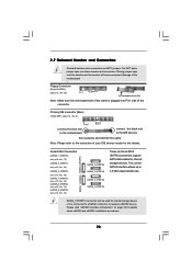
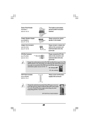
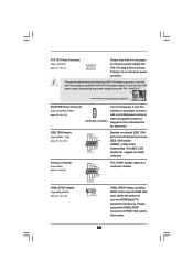
... 2 GND 1 Please connect the CPU fan cable to Pin 1-3. If you adopt a traditional 20-pin ATX power supply. Please connect a chassis fan cable to this motherboard provides 24-pin ATX power connector, 12 24 it can work if you plan to connect the 3-Pin CPU fan to the CPU fan connector... on this motherboard, please connect it to this header. Pin 1-3 Connected 3-Pin Fan Installation ATX Power Connector (24-pin ATXPWR1) (see p.12, No. 24) PLED+ PLEDPWRBTN# GND 1 DUMMY...
... 2 GND 1 Please connect the CPU fan cable to Pin 1-3. If you adopt a traditional 20-pin ATX power supply. Please connect a chassis fan cable to this motherboard provides 24-pin ATX power connector, 12 24 it can work if you plan to connect the 3-Pin CPU fan to the CPU fan connector... on this motherboard, please connect it to this header. Pin 1-3 Connected 3-Pin Fan Installation ATX Power Connector (24-pin ATXPWR1) (see p.12, No. 24) PLED+ PLEDPWRBTN# GND 1 DUMMY...
User Manual
Page 30
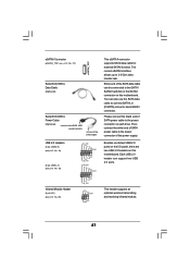
... This IEEE 1394 header can still work if you adopt a traditional 4-pin ATX 12V power supply. Failing to this header. 30 Though this motherboard provides 8-pin ATX 12V power connector, it can support one IEEE 1394 header (FRONT_1394) on the I/O panel, there is one IEEE 1394 ... Header (3-pin HDMI_SPDIF1) (see p.12 No. 22) RXTPAM_0 GND RXTPBM_0 +12V GND 1 +12V RXTPBP_0 GND RXTPAP_0 Besides one default IEEE 1394 port on this motherboard. To use the 4-pin ATX power supply, please plug your power supply along with Pin 1 and Pin 5. 8 5 4-Pin ATX 12V Power Supply Installation ...
... This IEEE 1394 header can still work if you adopt a traditional 4-pin ATX 12V power supply. Failing to this header. 30 Though this motherboard provides 8-pin ATX 12V power connector, it can support one IEEE 1394 header (FRONT_1394) on the I/O panel, there is one IEEE 1394 ... Header (3-pin HDMI_SPDIF1) (see p.12 No. 22) RXTPAM_0 GND RXTPBM_0 +12V GND 1 +12V RXTPBP_0 GND RXTPAP_0 Besides one default IEEE 1394 port on this motherboard. To use the 4-pin ATX power supply, please plug your power supply along with Pin 1 and Pin 5. 8 5 4-Pin ATX 12V Power Supply Installation ...
User Manual
Page 31
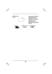
Then connect the white end (B or C) of HDMI VGA card. white end (3-pin) SPDIFOUT GND blue black 31 white end (2-pin) SPDIFOUT GND blue black C. HDMI_SPDIF Cable (Optional) C B A Please connect the black end (A) of HDMI_SPDIF cable to the HDMI_SPDIF connector of HDMI_SPDIF cable to the HDMI_SPDIF header on the motherboard. A. black end +5V SPDIFOUT GND blue black B.
Then connect the white end (B or C) of HDMI VGA card. white end (3-pin) SPDIFOUT GND blue black 31 white end (2-pin) SPDIFOUT GND blue black C. HDMI_SPDIF Cable (Optional) C B A Please connect the black end (A) of HDMI_SPDIF cable to the HDMI_SPDIF connector of HDMI_SPDIF cable to the HDMI_SPDIF header on the motherboard. A. black end +5V SPDIFOUT GND blue black B.

