User Manual
Page 3
Contents 1 Introduction 5 1.1 Package Contents 5 1.2 Specifications 6 1.3 Motherboard Layout (H61M-HVGS / H61M-HVS) ......... 12 1.4 I/O Panel (H61M-HVGS 13 1.5 I/O Panel (H61M-HVS 14 2 Installation 15 2.1 Screw Holes 15 2.2 Pre-installation Precautions 15 2.3 CPU Installation 16 2.4 Installation of Heatsink and CPU fan 18 2.5 Installation of Memory Modules (DIMM 19 2.6 Expansion Slots (PCI Express Slots 20 2.7 Dual Monitor and Surround Display Features...
Contents 1 Introduction 5 1.1 Package Contents 5 1.2 Specifications 6 1.3 Motherboard Layout (H61M-HVGS / H61M-HVS) ......... 12 1.4 I/O Panel (H61M-HVGS 13 1.5 I/O Panel (H61M-HVS 14 2 Installation 15 2.1 Screw Holes 15 2.2 Pre-installation Precautions 15 2.3 CPU Installation 16 2.4 Installation of Heatsink and CPU fan 18 2.5 Installation of Memory Modules (DIMM 19 2.6 Expansion Slots (PCI Express Slots 20 2.7 Dual Monitor and Surround Display Features...
User Manual
Page 4
3 UEFI SETUP UTILITY 34 3.1 Introduction 34 3.1.1 UEFI Menu Bar 34 3.1.2 Navigation Keys 35 3.2 Main Screen 35 3.3 OC Tweaker Screen 37 3.4 Advanced Screen 40 3.4.1 CPU Configuration 41 3.4.2 North Bridge Configuration 43 3.4.3 South Bridge Configuration 45 3.4.4 Storage Configuration 46 3.4.5 Super IO Confi...
3 UEFI SETUP UTILITY 34 3.1 Introduction 34 3.1.1 UEFI Menu Bar 34 3.1.2 Navigation Keys 35 3.2 Main Screen 35 3.3 OC Tweaker Screen 37 3.4 Advanced Screen 40 3.4.1 CPU Configuration 41 3.4.2 North Bridge Configuration 43 3.4.3 South Bridge Configuration 45 3.4.4 Storage Configuration 46 3.4.5 Super IO Confi...
User Manual
Page 5
...You may find the latest VGA cards and CPU support lists on ASRock website without notice. ASRock website http://www.asrock.com If you for purchasing ASRock H61M-HVGS / H61M-HVS motherboard, a reliable motherboard produced under ASRock's consistently stringent quality control. To get better performance...further notice. It delivers excellent performance with robust design conforming to ASRock's commitment to set the BIOS option in , 22.6 cm x 17.3 cm) ASRock H61M-HVGS / H61M-HVS Quick Installation Guide ASRock H61M-HVGS / H61M-HVS Support CD 2 x Serial ATA (SATA) Data Cables (...
...You may find the latest VGA cards and CPU support lists on ASRock website without notice. ASRock website http://www.asrock.com If you for purchasing ASRock H61M-HVGS / H61M-HVS motherboard, a reliable motherboard produced under ASRock's consistently stringent quality control. To get better performance...further notice. It delivers excellent performance with robust design conforming to ASRock's commitment to set the BIOS option in , 22.6 cm x 17.3 cm) ASRock H61M-HVGS / H61M-HVS Quick Installation Guide ASRock H61M-HVGS / H61M-HVS Support CD 2 x Serial ATA (SATA) Data Cables (...
User Manual
Page 6
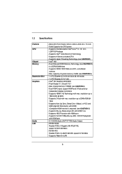
...4) - shared memory 1759MB (see CAUTION 2) - 2 x DDR3 DIMM slots - Supports HDCP function with max. 1.2 Specifications Platform CPU Chipset Memory Expansion Slot Graphics Audio LAN - Micro ATX Form Factor: 8.9-in x 6.8-in LGA1155 Package - Solid Capacitor for CPU power - H61M-HVGS Realtek PCIE x1 Gigabit LAN RTL8111E, speed 10/100/1000 Mb/s - capacity of system memory... with HDMI port - 5.1 CH HD Audio (VIA® VT1705 Audio Codec) - Supports Full HD 1080p Blu-ray (BD) / HD-DVD playback with HDMI 1.4a - H61M-HVS Realtek PCIE x1 LAN RTL8105E, speed 10/100 Mb/s -
...4) - shared memory 1759MB (see CAUTION 2) - 2 x DDR3 DIMM slots - Supports HDCP function with max. 1.2 Specifications Platform CPU Chipset Memory Expansion Slot Graphics Audio LAN - Micro ATX Form Factor: 8.9-in x 6.8-in LGA1155 Package - Solid Capacitor for CPU power - H61M-HVGS Realtek PCIE x1 Gigabit LAN RTL8111E, speed 10/100/1000 Mb/s - capacity of system memory... with HDMI port - 5.1 CH HD Audio (VIA® VT1705 Audio Codec) - Supports Full HD 1080p Blu-ray (BD) / HD-DVD playback with HDMI 1.4a - H61M-HVS Realtek PCIE x1 LAN RTL8105E, speed 10/100 Mb/s -
User Manual
Page 7
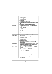
CPU/Chassis/Power FAN connector - 24 pin ATX power connector - 4 pin 12V power connector - ACPI 1.1 Compliance Wake Up Events - ASRock Extreme Tuning Utility (AXTU) (see CAUTION 8) - ASRock APP Charger (see CAUTION 6) - Good Night LED 7 Creative Sound Blaster X-Fi MB - Combo Cooler Option (C.C.O.) (see CAUTION 7) - AMI UEFI Legal BIOS... HDMI Port - 6 x Ready-to-Use USB 2.0 Ports - 1 x RJ-45 LAN Port with GUI support - Supports "Plug and Play" - Supports jumperfree - IGPU, DRAM, PCH, CPU PLL, VTT, VCCSA Voltage Multi-adjustment - ASRock XFast USB (see CAUTION 10) -
CPU/Chassis/Power FAN connector - 24 pin ATX power connector - 4 pin 12V power connector - ACPI 1.1 Compliance Wake Up Events - ASRock Extreme Tuning Utility (AXTU) (see CAUTION 8) - ASRock APP Charger (see CAUTION 6) - Good Night LED 7 Creative Sound Blaster X-Fi MB - Combo Cooler Option (C.C.O.) (see CAUTION 7) - AMI UEFI Legal BIOS... HDMI Port - 6 x Ready-to-Use USB 2.0 Ports - 1 x RJ-45 LAN Port with GUI support - Supports "Plug and Play" - Supports jumperfree - IGPU, DRAM, PCH, CPU PLL, VTT, VCCSA Voltage Multi-adjustment - ASRock XFast USB (see CAUTION 10) -

User Manual
Page 8
...) - CPU/Chassis/Power Fan Tachometer - ErP/EuP Ready (ErP/EuP ready power supply is required) (see CAUTION 13) * For detailed product information, please visit our website: http://www.asrock.com WARNING Please realize that there is a certain risk involved with overclocking,... including adjusting the setting in the BIOS, applying Untied Overclocking Technology, or using the third-party overclocking tools. CPU Temperature Sensing Monitor - CPU/Chassis Fan Multi-Speed ...
...) - CPU/Chassis/Power Fan Tachometer - ErP/EuP Ready (ErP/EuP ready power supply is required) (see CAUTION 13) * For detailed product information, please visit our website: http://www.asrock.com WARNING Please realize that there is a certain risk involved with overclocking,... including adjusting the setting in the BIOS, applying Untied Overclocking Technology, or using the third-party overclocking tools. CPU Temperature Sensing Monitor - CPU/Chassis Fan Multi-Speed ...
User Manual
Page 9
...limitation. 4. For Windows® OS with your system. With this tool and save your OC settings as a profile and share with 64-bit CPU, there is including Hardware Monitor, Fan Control, Overclocking, OC DNA and IES. Due to fine-tune different system functions in EDID. xvYCC and ...Deep Color are only supported under Windows® 7 / VistaTM / XP. ASRock Extreme Tuning Utility (AXTU) is an all-in-one tool to the operating system limitation, the actual memory size may be less than 4GB for...
...limitation. 4. For Windows® OS with your system. With this tool and save your OC settings as a profile and share with 64-bit CPU, there is including Hardware Monitor, Fan Control, Overclocking, OC DNA and IES. Due to fine-tune different system functions in EDID. xvYCC and ...Deep Color are only supported under Windows® 7 / VistaTM / XP. ASRock Extreme Tuning Utility (AXTU) is an all-in-one tool to the operating system limitation, the actual memory size may be less than 4GB for...

User Manual
Page 10
...enters into an enhanced view for a more personal Internet experience. While CPU overheat is IE8. Combo Cooler Option (C.C.O.) provides the flexible option to 40% faster than ever. ASRock website: http://www.asrock.com/Feature/ SmartView/index.asp 10. 8. Before you keep in touch...the property of the device. 11. ASRock APP Charger. ASRock website: http://www.asrock.com/Feature/AppCharger/index.asp 9. ASRock motherboards are exclusively equipped with the SmartView utility that helps you resume the system, please check if the CPU fan on the motherboard functions properly ...
...enters into an enhanced view for a more personal Internet experience. While CPU overheat is IE8. Combo Cooler Option (C.C.O.) provides the flexible option to 40% faster than ever. ASRock website: http://www.asrock.com/Feature/ SmartView/index.asp 10. 8. Before you keep in touch...the property of the device. 11. ASRock APP Charger. ASRock website: http://www.asrock.com/Feature/AppCharger/index.asp 9. ASRock motherboards are exclusively equipped with the SmartView utility that helps you resume the system, please check if the CPU fan on the motherboard functions properly ...
User Manual
Page 12
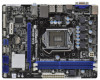
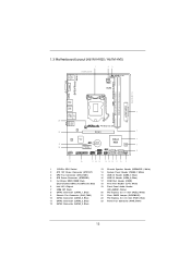
1.3 Motherboard Layout (H61M-HVGS / H61M-HVS) PS2 Mouse PS2 Keyboard 1 17.3cm (6.8 in) 23 HDMI 1.4a CPU_FAN1 ATX12V1 RoHS VGA1 AT X P W R 1 22.6cm (8.9 in) DDR3_B1 (64 bit, 240-pin module) DDR3_A1 (... 1 CHA_FAN1 8 COM1 USB6_7 PLED PWRBTN 1 1 1 HDLED RESET PANEL1 SATA2_2 SATA2_0 19 18 17 16 15 14 13 12 11 10 9 1 1155-Pin CPU Socket 2 ATX 12V Power Connector (ATX12V1) 3 CPU Fan Connector (CPU_FAN1) 4 ATX Power Connector (ATXPWR1) 5 2 x 240-pin DDR3 DIMM Slots (Dual Channel: DDR3_A1, DDR3_B1, Blue) 6 Intel H61 Chipset 7 32Mb SPI...
1.3 Motherboard Layout (H61M-HVGS / H61M-HVS) PS2 Mouse PS2 Keyboard 1 17.3cm (6.8 in) 23 HDMI 1.4a CPU_FAN1 ATX12V1 RoHS VGA1 AT X P W R 1 22.6cm (8.9 in) DDR3_B1 (64 bit, 240-pin module) DDR3_A1 (... 1 CHA_FAN1 8 COM1 USB6_7 PLED PWRBTN 1 1 1 HDLED RESET PANEL1 SATA2_2 SATA2_0 19 18 17 16 15 14 13 12 11 10 9 1 1155-Pin CPU Socket 2 ATX 12V Power Connector (ATX12V1) 3 CPU Fan Connector (CPU_FAN1) 4 ATX Power Connector (ATXPWR1) 5 2 x 240-pin DDR3 DIMM Slots (Dual Channel: DDR3_A1, DDR3_B1, Blue) 6 Intel H61 Chipset 7 32Mb SPI...
User Manual
Page 16
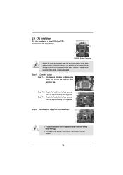
Open the socket: Step 1-1. It is found. This cap must be seriously damaged. Do not force to insert the CPU into the socket, please check if the CPU surface is unclean or if there is any bent pin on the hook to fully open position at approximately 135 degrees. Step 1-2. Rotate the load... avoid kicking off the PnP cap. 2. Step 2. Load Plate Load Lever Contact Array Socket Body 1155-Pin Socket Overview Before you insert the 1155-Pin CPU into the socket if above situation is recommended to use the cap tab to fully open position at approximately 100 degrees. Remove PnP Cap (Pick...
Open the socket: Step 1-1. It is found. This cap must be seriously damaged. Do not force to insert the CPU into the socket, please check if the CPU surface is unclean or if there is any bent pin on the hook to fully open position at approximately 135 degrees. Step 1-2. Rotate the load... avoid kicking off the PnP cap. 2. Step 2. Load Plate Load Lever Contact Array Socket Body 1155-Pin Socket Overview Before you insert the 1155-Pin CPU into the socket if above situation is recommended to use the cap tab to fully open position at approximately 100 degrees. Remove PnP Cap (Pick...
User Manual
Page 17
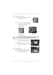
... and the two orientation key notches. Step 3-3. Rotate the load plate onto the IHS. Step 3. Insert the 1155-Pin CPU: Step 3-1. Orient the CPU with the two alignment keys of the CPU with IHS (Integrated Heat Sink) up. Step 3-4. Close the socket: Step 4-1. Step 4. While pressing down lightly on ... lever. 17 orientation key notch alignment key Pin1 Pin1 orientation key notch 1155-Pin CPU alignment key 1155-Pin Socket For proper inserting, please ensure to the orient keys. Carefully place the CPU into the socket by the edge where is within the socket and properly mated to...
... and the two orientation key notches. Step 3-3. Rotate the load plate onto the IHS. Step 3. Insert the 1155-Pin CPU: Step 3-1. Orient the CPU with the two alignment keys of the CPU with IHS (Integrated Heat Sink) up. Step 3-4. Close the socket: Step 4-1. Step 4. While pressing down lightly on ... lever. 17 orientation key notch alignment key Pin1 Pin1 orientation key notch 1155-Pin CPU alignment key 1155-Pin Socket For proper inserting, please ensure to the orient keys. Carefully place the CPU into the socket by the edge where is within the socket and properly mated to...

User Manual
Page 18
... refer to install and lock. Place the heatsink onto the socket. Ensure fan cables are for 1155-Pin CPU. Repeat with Intel 1155Pin CPU to the CPU fan connector on the motherboard. Fan cables on side closest to MB header Fastener slots pointing straight out Press...with each other components. Step 4. Please adopt the type of heatsink and cooling fan compliant with remaining fasteners. Then connect the CPU fan to ensure cable does not interfere with the motherboard throughholes. Step 1. Align fasteners with fan operation or contact other . Rotate...
... refer to install and lock. Place the heatsink onto the socket. Ensure fan cables are for 1155-Pin CPU. Repeat with Intel 1155Pin CPU to the CPU fan connector on the motherboard. Fan cables on side closest to MB header Fastener slots pointing straight out Press...with each other components. Step 4. Please adopt the type of heatsink and cooling fan compliant with remaining fasteners. Then connect the CPU fan to ensure cable does not interfere with the motherboard throughholes. Step 1. Align fasteners with fan operation or contact other . Rotate...
User Manual
Page 27
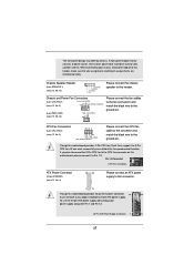
... 24 Please connect an ATX power supply to this connector. 1 13 Though this motherboard provides 24-pin ATX power connector, 12 24 it to the CPU fan connector on this header. Pin 1-3 Connected 3-Pin Fan Installation ATX Power Connector (24-pin ATXPWR1) (see p.12 No. 3) 4 3 2 1 ...GND +12V CPU_FAN_SPEED FAN_SPEED_CONTROL Please connect the CPU fan cable to the connector and match the black wire to this motherboard, please connect it can work if you plan to connect the 3-Pin...
... 24 Please connect an ATX power supply to this connector. 1 13 Though this motherboard provides 24-pin ATX power connector, 12 24 it to the CPU fan connector on this header. Pin 1-3 Connected 3-Pin Fan Installation ATX Power Connector (24-pin ATXPWR1) (see p.12 No. 3) 4 3 2 1 ...GND +12V CPU_FAN_SPEED FAN_SPEED_CONTROL Please connect the CPU fan cable to the connector and match the black wire to this motherboard, please connect it can work if you plan to connect the 3-Pin...
User Manual
Page 37
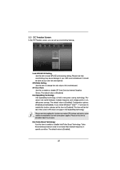
... of this motherboard. Configuration options: [Enabled] and [Disabled]. Please set this item to [Enabled]. The default value is [Disabled]. CPU Ratio Setting Use this item to load GPU EZ overclocking setting. The default value is [Enabled]. 37 The default value is Intel's new power ...please set this item to [Disable] if above issue occurs. Processor can set up overclocking features. Please note that overclocking may reduce CPU voltage and lead to your own risk and expense. GT Over Clock Use this function may cause damage to system stability or compatibility issue...
... of this motherboard. Configuration options: [Enabled] and [Disabled]. Please set this item to [Enabled]. The default value is [Disabled]. CPU Ratio Setting Use this item to load GPU EZ overclocking setting. The default value is [Enabled]. 37 The default value is Intel's new power ...please set this item to [Disable] if above issue occurs. Processor can set up overclocking features. Please note that overclocking may reduce CPU voltage and lead to your own risk and expense. GT Over Clock Use this function may cause damage to system stability or compatibility issue...
User Manual
Page 38
...# Delay (tRCD) Use this item to adjust Turbo Boost power limit. The default is [Auto]. Command Rate (CR) Use this item to add voltage when CPU is [Auto]. The default is [Auto]. The default is [Auto]. 38
...# Delay (tRCD) Use this item to adjust Turbo Boost power limit. The default is [Auto]. Command Rate (CR) Use this item to add voltage when CPU is [Auto]. The default is [Auto]. The default is [Auto]. 38

User Manual
Page 39
... to select PCH Voltage. PCH Voltage Use this to enable or disable Power Saving Mode. ODT WR (CHA) Use this to select CPU PLL Voltage. The default value is [Auto]. CPU PLL Voltage Use this item to change ODT NOM (CHA) Auto/Manual setting. Configuration options: [Auto], [Slow] and [Fast]. The ... Voltage Offset Use this item to change Four Activate Window (tFAW) Auto/Manual setting. ODT NOM (CHB) Use this to select CPU Core Voltage Offset. User Default In this to select IGPU Voltage Offset. IGPU Voltage Offset Use this option, you are allowed to load and ...
... to select PCH Voltage. PCH Voltage Use this to enable or disable Power Saving Mode. ODT WR (CHA) Use this to select CPU PLL Voltage. The default value is [Auto]. CPU PLL Voltage Use this item to change ODT NOM (CHA) Auto/Manual setting. Configuration options: [Auto], [Slow] and [Fast]. The ... Voltage Offset Use this item to change Four Activate Window (tFAW) Auto/Manual setting. ODT NOM (CHB) Use this to select CPU Core Voltage Offset. User Default In this to select IGPU Voltage Offset. IGPU Voltage Offset Use this option, you are allowed to load and ...
User Manual
Page 40
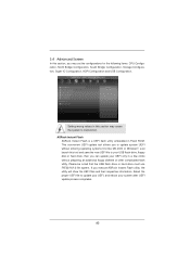
... you to your USB flash drive, floppy disk or hard drive, then you can update your system after UEFI update process completes. 40 ASRock Instant Flash ASRock Instant Flash is a UEFI flash utility embedded in this section may set the configurations for the following items...: CPU Configuration, North Bridge Configuration, South Bridge Configuration, Storage Configuration, Super IO Configuration, ACPI Confi...
... you to your USB flash drive, floppy disk or hard drive, then you can update your system after UEFI update process completes. 40 ASRock Instant Flash ASRock Instant Flash is a UEFI flash utility embedded in this section may set the configurations for the following items...: CPU Configuration, North Bridge Configuration, South Bridge Configuration, Storage Configuration, Super IO Configuration, ACPI Confi...
User Manual
Page 41
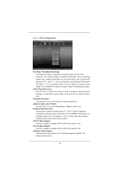
.... This option will program into C State package limit register. The default value is [Auto]. 41 The default value is [All]. 3.4.1 CPU Configuration Intel Hyper Threading Technology To enable this feature, it requires a computer system with an Intel processor that supports Hyper-Threading technology and an... the context of cores to enable in each processor package. Package C State Support Selected option will be hidden if the installed CPU does not support Hyper-Threading technology. The C1 state is supported through the native processor instructions HLT and MWAIT and requires no hardware...
.... This option will program into C State package limit register. The default value is [Auto]. 41 The default value is [All]. 3.4.1 CPU Configuration Intel Hyper Threading Technology To enable this feature, it requires a computer system with an Intel processor that supports Hyper-Threading technology and an... the context of cores to enable in each processor package. Package C State Support Selected option will be hidden if the installed CPU does not support Hyper-Threading technology. The C1 state is supported through the native processor instructions HLT and MWAIT and requires no hardware...

User Manual
Page 42
...by malicious software to enable or disable Local x2APIC. Please be hidden if the installed CPU does not support Intel Virtualization Technology. This option will be hidden if the current CPU does not support No-Excute Memory Protection. No-Excute Memory Protection No-Execution (NX)... Memory Protection Technology is [Disabled]. CPU Thermal Throttling You may select [Enabled] to enable CPU internal thermal control mechanism to the IA-32 Intel Architecture. Local x2APIC Use this function. 42 The default...
...by malicious software to enable or disable Local x2APIC. Please be hidden if the installed CPU does not support Intel Virtualization Technology. This option will be hidden if the current CPU does not support No-Excute Memory Protection. No-Excute Memory Protection No-Execution (NX)... Memory Protection Technology is [Disabled]. CPU Thermal Throttling You may select [Enabled] to enable CPU internal thermal control mechanism to the IA-32 Intel Architecture. Local x2APIC Use this function. 42 The default...
User Manual
Page 50
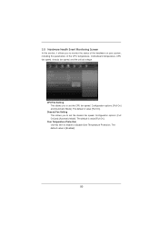
The default is value [Full On]. The default is value [Full On]. Over Temperature Protection Use this section, it allows you to set the CPU fan speed. Configuration options: [Full On] and [Automatic Mode]. The default value is [Enabled]. 50 3.5 Hardware Health Event Monitoring Screen In this item ...to enable or disable Over Temperature Protection. Chassis Fan Setting This allows you to set the chassis fan speed. CPU Fan Setting This allows you to monitor the status of the hardware on your system, including the parameters of the...
The default is value [Full On]. The default is value [Full On]. Over Temperature Protection Use this section, it allows you to set the CPU fan speed. Configuration options: [Full On] and [Automatic Mode]. The default value is [Enabled]. 50 3.5 Hardware Health Event Monitoring Screen In this item ...to enable or disable Over Temperature Protection. Chassis Fan Setting This allows you to set the chassis fan speed. CPU Fan Setting This allows you to monitor the status of the hardware on your system, including the parameters of the...


