User Manual
Page 3
... Motherboard Layout 12 1.4 I/O Panel 13 2 Installation 15 2.1 Screw Holes 15 2.2 Pre-installation Precautions 15 2.3 CPU Installation 16 2.4 Installation of Heatsink and CPU fan 18 2.5 Installation of Memory Modules (DIMM 19 2.6 Expansion Slots (PCI and PCI Express Slots 21 2.7 Dual Monitor and Surround Display Features 22 2.8 ASRock Smart Remote Installation Guide 25 2.9 Jumpers Setup 26 2.10 Onboard Headers and Connectors 27 2.11 Serial ATA (SATA) / Serial ATAII (SATAII) Hard Disks Installation 31 2.12 Hot Plug Function for SATA / SATAII HDDs 31 2.13 SATA / SATAII HDD Hot Plug...
... Motherboard Layout 12 1.4 I/O Panel 13 2 Installation 15 2.1 Screw Holes 15 2.2 Pre-installation Precautions 15 2.3 CPU Installation 16 2.4 Installation of Heatsink and CPU fan 18 2.5 Installation of Memory Modules (DIMM 19 2.6 Expansion Slots (PCI and PCI Express Slots 21 2.7 Dual Monitor and Surround Display Features 22 2.8 ASRock Smart Remote Installation Guide 25 2.9 Jumpers Setup 26 2.10 Onboard Headers and Connectors 27 2.11 Serial ATA (SATA) / Serial ATAII (SATAII) Hard Disks Installation 31 2.12 Hot Plug Function for SATA / SATAII HDDs 31 2.13 SATA / SATAII HDD Hot Plug...
User Manual
Page 9
The maximum shared memory size is de ned by the chipset vendor and is subject to -HDMI adapter, the DVI-D port can support the same features as a pro le and share with your friends. Besides, with 64-bit CPU, there is including Hardware Monitor, Fan Control, Overclocking, OC DNA and IES. For audio output, this motherboard supports both stereo and mono modes. Your friends then can save your...
The maximum shared memory size is de ned by the chipset vendor and is subject to -HDMI adapter, the DVI-D port can support the same features as a pro le and share with your friends. Besides, with 64-bit CPU, there is including Hardware Monitor, Fan Control, Overclocking, OC DNA and IES. For audio output, this motherboard supports both stereo and mono modes. Your friends then can save your...
User Manual
Page 10
... SmartView utility that the USB ash drive or hard drive must use SmartView feature, please make sure your OS version is Windows® 7 / 7 64 bit / VistaTM / VistaTM 64 bit, and your browser version is the smart start experiencing the exciting motion controlled games. Please be noted that helps you to access ASRock Instant Flash. ASRock AIWI is just to install the ASRock AIWI utility either from ASRock of charging your PC enters into...
... SmartView utility that the USB ash drive or hard drive must use SmartView feature, please make sure your OS version is Windows® 7 / 7 64 bit / VistaTM / VistaTM 64 bit, and your browser version is the smart start experiencing the exciting motion controlled games. Please be noted that helps you to access ASRock Instant Flash. ASRock AIWI is just to install the ASRock AIWI utility either from ASRock of charging your PC enters into...
User Manual
Page 12
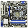
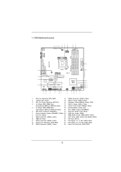
...-pin DDR3 DIMM Slots 19 Infrared Module Header (IR1) (Dual Channel: DDR3_A2, DDR3_B2, White) 20 Clear CMOS Jumper (CLRCMOS1) 6 ATX Power Connector (ATXPWR1) 21 Print Port Header (LPT1, White) 7 Chassis Speaker Header (SPEAKER 1, White) 22 COM Port Header (COM1) 8 Intel H61 Chipset 23 HDMI_SPDIF Header (HDMI_SPDIF1, White) 9 SATA2 Connector (SATA2_2, Blue) 24 Front Panel Audio Header (HD_AUDIO1, White) 10 32Mb SPI Flash 25 PCI Slots (PCI1-2) 11 SATA2 Connector (SATA2_0, Blue) 26 PCI Express 2.0 x1 Slot (PCIE2, White) 12 Chassis Fan Connector (CHA_FAN1) 27 PCI Express 2.0 x16 Slot...
...-pin DDR3 DIMM Slots 19 Infrared Module Header (IR1) (Dual Channel: DDR3_A2, DDR3_B2, White) 20 Clear CMOS Jumper (CLRCMOS1) 6 ATX Power Connector (ATXPWR1) 21 Print Port Header (LPT1, White) 7 Chassis Speaker Header (SPEAKER 1, White) 22 COM Port Header (COM1) 8 Intel H61 Chipset 23 HDMI_SPDIF Header (HDMI_SPDIF1, White) 9 SATA2 Connector (SATA2_2, Blue) 24 Front Panel Audio Header (HD_AUDIO1, White) 10 32Mb SPI Flash 25 PCI Slots (PCI1-2) 11 SATA2 Connector (SATA2_0, Blue) 26 PCI Express 2.0 x1 Slot (PCIE2, White) 12 Chassis Fan Connector (CHA_FAN1) 27 PCI Express 2.0 x16 Slot...
User Manual
Page 22
... HDMI to this motherboard. If you have installed onboard VGA driver from our support CD to your system already, you haven't installed onboard VGA driver yet, please install onboard VGA driver from our support CD to VGA/D-Sub port on the I /O panel. To enable dual monitor feature, please follow the below steps: 1. Connect DVI-D monitor cable to VGA/DVI-D port on the I/O panel, connect D-Sub monitor cable to your system and restart your system boots. VGA/D-Sub port VGA/DVI-D port HDMI port 2. You can drive same or different display...
... HDMI to this motherboard. If you have installed onboard VGA driver from our support CD to your system already, you haven't installed onboard VGA driver yet, please install onboard VGA driver from our support CD to VGA/D-Sub port on the I /O panel. To enable dual monitor feature, please follow the below steps: 1. Connect DVI-D monitor cable to VGA/DVI-D port on the I/O panel, connect D-Sub monitor cable to your system and restart your system boots. VGA/D-Sub port VGA/DVI-D port HDMI port 2. You can drive same or different display...

User Manual
Page 23
... connect HDMI monitor cable to install them again. 5. G. Connect DVI-D monitor cable to VGA/DVI-D port on the I/O panel, connect D-Sub monitor cable to your card, one , two, three and four. 23 Boot your primary monitor, and then select "Primary". Enter "Onboard VGA Share Memory" option to adjust the memory capability to [32MB], [64MB], [128MB], [256MB] or [512MB] to set up a multi-monitor display. If you use multiple monitors with your system. When you do not adjust the UEFI setup...
... connect HDMI monitor cable to install them again. 5. G. Connect DVI-D monitor cable to VGA/DVI-D port on the I/O panel, connect D-Sub monitor cable to your card, one , two, three and four. 23 Boot your primary monitor, and then select "Primary". Enter "Onboard VGA Share Memory" option to adjust the memory capability to [32MB], [64MB], [128MB], [256MB] or [512MB] to set up a multi-monitor display. If you use multiple monitors with your system. When you do not adjust the UEFI setup...

User Manual
Page 34
... drivers. Enter UEFI SETUP UTILITY Advanced screen SATA Configuration. Using SATA / SATAII HDDs with NCQ function STEP 1: Set Up UEFI. B. Set the option "SATA Mode" to format the floppy diskette and copy SATA / SATAII drivers into the floppy drive. WARNING! E. D. Then you want to install Windows® XP / XP 64-bit OS on the support CD driver page. A. STEP 2: Make a SATA / SATAII driver diskette. (Please use USB floppy or floppy disk.) A. 2.14 Driver Installation Guide To install...
... drivers. Enter UEFI SETUP UTILITY Advanced screen SATA Configuration. Using SATA / SATAII HDDs with NCQ function STEP 1: Set Up UEFI. B. Set the option "SATA Mode" to format the floppy diskette and copy SATA / SATAII drivers into the floppy drive. WARNING! E. D. Then you want to install Windows® XP / XP 64-bit OS on the support CD driver page. A. STEP 2: Make a SATA / SATAII driver diskette. (Please use USB floppy or floppy disk.) A. 2.14 Driver Installation Guide To install...
User Manual
Page 42
... using Microsoft® Windows® XP, VistaTM, 7, or Linux kernel version 2.4.18 or higher. The C1 state is [Auto]. 42 3.4.1 CPU Configuration Intel Hyper Threading Technology To enable this feature, it requires a computer system with an Intel processor that supports Hyper-Threading technology and an operating system that includes optimization for this item to turn on /off the MLC streamer prefetcher. The default...
... using Microsoft® Windows® XP, VistaTM, 7, or Linux kernel version 2.4.18 or higher. The C1 state is [Auto]. 42 3.4.1 CPU Configuration Intel Hyper Threading Technology To enable this feature, it requires a computer system with an Intel processor that supports Hyper-Threading technology and an operating system that includes optimization for this item to turn on /off the MLC streamer prefetcher. The default...
User Manual
Page 44
... by Internal Graphics Device. Con guration options: [Auto], [32MB], [64MB], [128MB], [256MB] and [512MB]. IGD Multi-Monitor Use this memory with other system components. In DVMT mode, the graphics driver allocates memory as needed for the motherboard through ef cient memory utilization. 3.4.2 North Bridge Configuration Low MMIO Align Low MMIO resources align at 64MB/1024MB. VT-d Use this option to enable or disable IGD Multi-Monitor by Internal Graphics Device. The default value is [PCI Express]. The default...
... by Internal Graphics Device. Con guration options: [Auto], [32MB], [64MB], [128MB], [256MB] and [512MB]. IGD Multi-Monitor Use this memory with other system components. In DVMT mode, the graphics driver allocates memory as needed for the motherboard through ef cient memory utilization. 3.4.2 North Bridge Configuration Low MMIO Align Low MMIO resources align at 64MB/1024MB. VT-d Use this option to enable or disable IGD Multi-Monitor by Internal Graphics Device. The default value is [PCI Express]. The default...
User Manual
Page 50
...USB 2.0 controller. 3.4.7 USB Configuration USB 2.0 Controller Use this option to select legacy support for USB devices. Please refer to below descriptions for legacy USB. [Auto] - There are connected. [Disabled] - The default value is recommended to select [Disabled] to enable or disable the use of these four options: [Enabled] - Legacy USB Support Use this item to enter OS. [UEFI Setup Only] - If you have USB compatibility issue, it is [Enabled]. Enables legacy support if USB devices are four con guration options: [Enabled], [Auto], [Disabled] and [UEFI Setup Only]. USB...
...USB 2.0 controller. 3.4.7 USB Configuration USB 2.0 Controller Use this option to select legacy support for USB devices. Please refer to below descriptions for legacy USB. [Auto] - There are connected. [Disabled] - The default value is recommended to select [Disabled] to enable or disable the use of these four options: [Enabled] - Legacy USB Support Use this item to enter OS. [UEFI Setup Only] - If you have USB compatibility issue, it is [Enabled]. Enables legacy support if USB devices are four con guration options: [Enabled], [Auto], [Disabled] and [UEFI Setup Only]. USB...
User Manual
Page 55
... to install it. 4.2.4 Contact Information If you may contact your dealer for general reference only. Because motherboard settings and hardware options vary, use the setup procedures in the Support CD to visit ASRock's website at http://www.asrock.com; Refer to your OS documentation for more about ASRock, welcome to display the menus. 4.2.2 Drivers Menu The Drivers Menu shows the available devices drivers if the system detects installed devices.
... to install it. 4.2.4 Contact Information If you may contact your dealer for general reference only. Because motherboard settings and hardware options vary, use the setup procedures in the Support CD to visit ASRock's website at http://www.asrock.com; Refer to your OS documentation for more about ASRock, welcome to display the menus. 4.2.2 Drivers Menu The Drivers Menu shows the available devices drivers if the system detects installed devices.
Quick Installation Guide
Page 2
...-pin DDR3 DIMM Slots 19 Infrared Module Header (IR1) (Dual Channel: DDR3_A2, DDR3_B2, White) 20 Clear CMOS Jumper (CLRCMOS1) 6 ATX Power Connector (ATXPWR1) 21 Print Port Header (LPT1, White) 7 Chassis Speaker Header (SPEAKER 1, White) 22 COM Port Header (COM1) 8 Intel H61 Chipset 23 HDMI_SPDIF Header (HDMI_SPDIF1, White) 9 SATA2 Connector (SATA2_2, Blue) 24 Front Panel Audio Header (HD_AUDIO1, White) 10 32Mb SPI Flash 25 PCI Slots (PCI1-2) 11 SATA2 Connector (SATA2_0, Blue) 26 PCI Express 2.0 x1 Slot (PCIE2, White) 12 Chassis Fan Connector (CHA_FAN1) 27 PCI Express 2.0 x16 Slot...
...-pin DDR3 DIMM Slots 19 Infrared Module Header (IR1) (Dual Channel: DDR3_A2, DDR3_B2, White) 20 Clear CMOS Jumper (CLRCMOS1) 6 ATX Power Connector (ATXPWR1) 21 Print Port Header (LPT1, White) 7 Chassis Speaker Header (SPEAKER 1, White) 22 COM Port Header (COM1) 8 Intel H61 Chipset 23 HDMI_SPDIF Header (HDMI_SPDIF1, White) 9 SATA2 Connector (SATA2_2, Blue) 24 Front Panel Audio Header (HD_AUDIO1, White) 10 32Mb SPI Flash 25 PCI Slots (PCI1-2) 11 SATA2 Connector (SATA2_0, Blue) 26 PCI Express 2.0 x1 Slot (PCIE2, White) 12 Chassis Fan Connector (CHA_FAN1) 27 PCI Express 2.0 x16 Slot...
Quick Installation Guide
Page 3
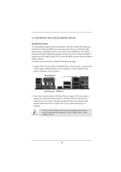
... Port 4 Central / Bass (Orange) 5 Rear Speaker (Black) 6 Optical SPDIF Out Port 7 Line In (Light Blue) 12 11 10 ** 8 9 10 11 12 13 14 Front Speaker (Lime) Microphone (Pink) USB 2.0 Ports (USB45) USB 2.0 Ports (USB23) VGA/HDMI Port VGA/DVI-D Port PS/2 Keyboard Port (Purple) * There are allowed to select "Realtek HDA Primary output" to use Rear Speaker, Central/Bass, and Front Speaker, or select "Realtek HDA Audio 2nd output" to use front panel audio. 3 ASRock H61M-GE Motherboard...
... Port 4 Central / Bass (Orange) 5 Rear Speaker (Black) 6 Optical SPDIF Out Port 7 Line In (Light Blue) 12 11 10 ** 8 9 10 11 12 13 14 Front Speaker (Lime) Microphone (Pink) USB 2.0 Ports (USB45) USB 2.0 Ports (USB23) VGA/HDMI Port VGA/DVI-D Port PS/2 Keyboard Port (Purple) * There are allowed to select "Realtek HDA Primary output" to use Rear Speaker, Central/Bass, and Front Speaker, or select "Realtek HDA Audio 2nd output" to use front panel audio. 3 ASRock H61M-GE Motherboard...
Quick Installation Guide
Page 4
... latest VGA cards and CPU support lists on ASRock website without notice. Introduction Thank you require technical support related to this manual occur, the updated version will be found in the user manual presented in , 24.4 cm x 24.4 cm) ASRock H61M-GE Quick Installation Guide ASRock H61M-GE Support CD 2 x Serial ATA (SATA) Data Cables (Optional) 1 x I/O Panel Shield ASRock Reminds You... For the BIOS setup, please refer to change without further notice. More detailed information of the motherboard and step-bystep installation guide. ASRock...
... latest VGA cards and CPU support lists on ASRock website without notice. Introduction Thank you require technical support related to this manual occur, the updated version will be found in the user manual presented in , 24.4 cm x 24.4 cm) ASRock H61M-GE Quick Installation Guide ASRock H61M-GE Support CD 2 x Serial ATA (SATA) Data Cables (Optional) 1 x I/O Panel Shield ASRock Reminds You... For the BIOS setup, please refer to change without further notice. More detailed information of the motherboard and step-bystep installation guide. ASRock...
Quick Installation Guide
Page 8
... change. In Hardware Monitor, it shows the fan speed and temperature for system usage under Windows® 7 / VistaTM / XP. In Fan Control, it shows the major readings of memory modules on page 3 for the latest information. 5. In Overclocking, you to overclock CPU frequency for proper installation. 3. In OC DNA, you implement Dual Channel Memory Technology, make sure to get the same OC settings. ASRock website: http://www.asrock.com 8 ASRock H61M-GE Motherboard English For Windows...
... change. In Hardware Monitor, it shows the fan speed and temperature for system usage under Windows® 7 / VistaTM / XP. In Fan Control, it shows the major readings of memory modules on page 3 for the latest information. 5. In Overclocking, you to overclock CPU frequency for proper installation. 3. In OC DNA, you implement Dual Channel Memory Technology, make sure to get the same OC settings. ASRock website: http://www.asrock.com 8 ASRock H61M-GE Motherboard English For Windows...
Quick Installation Guide
Page 9
.... ASRock XFast USB can press key during the POST or press key to BIOS setup menu to turn your iPhone/iPod touch as iPhone/iPod/iPad Touch, ASRock has prepared a wonderful solution for a more personal Internet experience. To experience intuitive motion controlled games is the smart start experiencing the exciting motion controlled games. Connecting your PC enters into an enhanced view for you can boost USB storage device performance. ASRock...
.... ASRock XFast USB can press key during the POST or press key to BIOS setup menu to turn your iPhone/iPod touch as iPhone/iPod/iPad Touch, ASRock has prepared a wonderful solution for a more personal Internet experience. To experience intuitive motion controlled games is the smart start experiencing the exciting motion controlled games. Connecting your PC enters into an enhanced view for you can boost USB storage device performance. ASRock...
Quick Installation Guide
Page 17
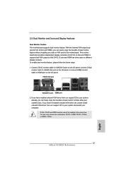
... VGA/DVI-D port on the I/O panel, connect D-Sub monitor cable to VGA/D-Sub port on the I/O panel, or connect HDMI monitor cable to HDMI port on VGA card to your system and restart your system boots. D-Sub, DVI-D and HDMI monitors cannot be enabled at the same time. You can drive same or different display contents. VGA/D-Sub port VGA/DVI-D port HDMI port 2. 2.5 Dual Monitor and Surround Display Features Dual Monitor Feature This motherboard supports dual monitor feature. If you have installed onboard VGA driver from our support CD to this motherboard. To enable dual monitor...
... VGA/DVI-D port on the I/O panel, connect D-Sub monitor cable to VGA/D-Sub port on the I/O panel, or connect HDMI monitor cable to HDMI port on VGA card to your system and restart your system boots. D-Sub, DVI-D and HDMI monitors cannot be enabled at the same time. You can drive same or different display contents. VGA/D-Sub port VGA/DVI-D port HDMI port 2. 2.5 Dual Monitor and Surround Display Features Dual Monitor Feature This motherboard supports dual monitor feature. If you have installed onboard VGA driver from our support CD to this motherboard. To enable dual monitor...
Quick Installation Guide
Page 18
... 2. Install the PCI Express VGA card on the I/O panel. Then connect other monitor cables to the corresponding connectors of surround display feature. Install the onboard VGA driver and the add-on PCIE1 slot. 3. Set up a surround display environment: 1. Surround Display Feature This motherboard supports surround display upgrade. Click the "Identify" button to display a large number on VGA card is no need to your system. G. Please refer to the following steps to enter UEFI setup. Press or to set up a multi-monitor display. E. Click...
... 2. Install the PCI Express VGA card on the I/O panel. Then connect other monitor cables to the corresponding connectors of surround display feature. Install the onboard VGA driver and the add-on PCIE1 slot. 3. Set up a surround display environment: 1. Surround Display Feature This motherboard supports surround display upgrade. Click the "Identify" button to display a large number on VGA card is no need to your system. G. Please refer to the following steps to enter UEFI setup. Press or to set up a multi-monitor display. E. Click...
Quick Installation Guide
Page 27
Set the option "SATA Mode" to install those required drivers. 2.9 Driver Installation Guide To install the drivers to your system, please insert the support CD to your system can work properly. 2.10 Installing Windows® 7 / 7 64-bit / VistaTM / VistaTM 64-bit / XP / XP 64-bit Without RAID Functions If you want to install Windows® XP / XP 64-bit OS on your system. 27 ASRock H61M-GE Motherboard English Then, the drivers compatible to your optical drive first. STEP...
Set the option "SATA Mode" to install those required drivers. 2.9 Driver Installation Guide To install the drivers to your system, please insert the support CD to your system can work properly. 2.10 Installing Windows® 7 / 7 64-bit / VistaTM / VistaTM 64-bit / XP / XP 64-bit Without RAID Functions If you want to install Windows® XP / XP 64-bit OS on your system. 27 ASRock H61M-GE Motherboard English Then, the drivers compatible to your optical drive first. STEP...
Quick Installation Guide
Page 29
3. otherwise, POST continues with the motherboard contains necessary drivers and useful utilities that will display the Main Menu automatically if "AUTORUN" is enabled in your CD-ROM drive. The BIOS Setup program is a menu-driven program, which allows you wish to the User Manual (PDF file) contained in the Support CD to select among the predetermined choices. Software Support CD information This motherboard supports various Microsoft® Windows® operating systems: 7 / 7 64-bit / VistaTM...
3. otherwise, POST continues with the motherboard contains necessary drivers and useful utilities that will display the Main Menu automatically if "AUTORUN" is enabled in your CD-ROM drive. The BIOS Setup program is a menu-driven program, which allows you wish to the User Manual (PDF file) contained in the Support CD to select among the predetermined choices. Software Support CD information This motherboard supports various Microsoft® Windows® operating systems: 7 / 7 64-bit / VistaTM...


