User Manual
Page 11
... recommend you checking with the power supply manufacturer for Energy Using Product, was a provision regulated by European Union to adopt three different CPU cooler types, Socket LGA 775, LGA 1155 and LGA 1156.
... recommend you checking with the power supply manufacturer for Energy Using Product, was a provision regulated by European Union to adopt three different CPU cooler types, Socket LGA 775, LGA 1155 and LGA 1156.
User Manual
Page 12
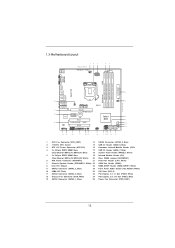
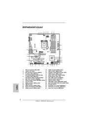
...7 SPEAKER1 24.4cm (9.6 in) Top: PWR_FAN1 CTR BASS LINE IN Center: REAR SPK FRONT Bottom: Optical SPDIF DX10.1 Top: Center: Bottom: MIC IN H61M-GE LAN PHY 27 PCIE1 PCI Express 2.0 26 CMOS PCIE2 Battery Super I/O PCI1 Intel 8 H61 9 25 ErP/EuP Ready RoHS AUDIO CODEC HD_AUDIO1 HDMI_SPDIF_1 1 1... 24 23 22 21 20 19 18 17 16 15 14 13 1 CPU Fan Connector (CPU_FAN1) 14 SATA2 Connector (SATA2_3, Blue) 2 1155-Pin CPU Socket 15 USB 2.0 Header (USB8_9, Blue) 3 ATX 12V Power Connector (ATX12V1) 16 Consumer Infrared Module Header (CIR1) 4 2 x 240-pin DDR3 DIMM ...
...7 SPEAKER1 24.4cm (9.6 in) Top: PWR_FAN1 CTR BASS LINE IN Center: REAR SPK FRONT Bottom: Optical SPDIF DX10.1 Top: Center: Bottom: MIC IN H61M-GE LAN PHY 27 PCIE1 PCI Express 2.0 26 CMOS PCIE2 Battery Super I/O PCI1 Intel 8 H61 9 25 ErP/EuP Ready RoHS AUDIO CODEC HD_AUDIO1 HDMI_SPDIF_1 1 1... 24 23 22 21 20 19 18 17 16 15 14 13 1 CPU Fan Connector (CPU_FAN1) 14 SATA2 Connector (SATA2_3, Blue) 2 1155-Pin CPU Socket 15 USB 2.0 Header (USB8_9, Blue) 3 ATX 12V Power Connector (ATX12V1) 16 Consumer Infrared Module Header (CIR1) 4 2 x 240-pin DDR3 DIMM ...

User Manual
Page 15
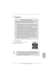
... power is switched off or the power cord is a Micro ATX form factor (9.6" x 9.6", 24.4 x 24.4 cm) motherboard. Chapter 2: Installation This is detached from the wall socket before you install motherboard components or change any motherboard settings. 1. To avoid damaging the motherboard components due to static electricity, NEVER place your chassis to...
... power is switched off or the power cord is a Micro ATX form factor (9.6" x 9.6", 24.4 x 24.4 cm) motherboard. Chapter 2: Installation This is detached from the wall socket before you install motherboard components or change any motherboard settings. 1. To avoid damaging the motherboard components due to static electricity, NEVER place your chassis to...

User Manual
Page 16
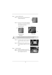
... any bent pin on the hook to fully open position at approximately 100 degrees. Disengaging the lever by depressing down and out on the socket. It is found. This cap must be seriously damaged. Otherwise, the CPU will be placed if returning the motherboard for after service. ...16 Rotate the load plate to clear retention tab. Step 2. Step 1. Open the socket: Step 1-1. Step 1-3. Rotate the load lever to handle and avoid kicking off the PnP cap. 2. 2.3 CPU Installation For the installation of Intel 1155...
... any bent pin on the hook to fully open position at approximately 100 degrees. Disengaging the lever by depressing down and out on the socket. It is found. This cap must be seriously damaged. Otherwise, the CPU will be placed if returning the motherboard for after service. ...16 Rotate the load plate to clear retention tab. Step 2. Step 1. Open the socket: Step 1-1. Step 1-3. Rotate the load lever to handle and avoid kicking off the PnP cap. 2. 2.3 CPU Installation For the installation of Intel 1155...
User Manual
Page 17
...proper inserting, please ensure to the orient keys. Carefully place the CPU into the socket by the edge where is within the socket and properly mated to match the two orientation key notches of the socket. Orient the CPU with the two alignment keys of the CPU with IHS (Integrated... Heat Sink) up. Step 3-4. Locate Pin1 and the two orientation key notches. Close the socket: Step 4-1. Step 4-2. black line Step 3-2. Insert the 1155-Pin CPU: Step 3-1. Verify that the CPU is marked with black line. Rotate the...
...proper inserting, please ensure to the orient keys. Carefully place the CPU into the socket by the edge where is within the socket and properly mated to match the two orientation key notches of the socket. Orient the CPU with the two alignment keys of the CPU with IHS (Integrated... Heat Sink) up. Step 3-4. Locate Pin1 and the two orientation key notches. Close the socket: Step 4-1. Step 4-2. black line Step 3-2. Insert the 1155-Pin CPU: Step 3-1. Verify that the CPU is marked with black line. Rotate the...
User Manual
Page 18
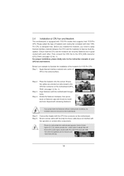
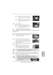
... for 1155-Pin CPU. Align fasteners with remaining fasteners. Connect fan header with each other components. Below is equipped with 1155-Pin socket that the CPU and the heatsink are securely fastened and in good contact with the CPU fan connector on the... CPU to improve heat dissipation. 2.4 Installation of CPU Fan and Heatsink This motherboard is an example to illustrate the installation of the heatsink for Socket LGA 1155/1156 CPU fan. 18 Before you installed the heatsink, you press down on the motherboard. Step 4. Repeat with the motherboard throughholes....
... for 1155-Pin CPU. Align fasteners with remaining fasteners. Connect fan header with each other components. Below is equipped with 1155-Pin socket that the CPU and the heatsink are securely fastened and in good contact with the CPU fan connector on the... CPU to improve heat dissipation. 2.4 Installation of CPU Fan and Heatsink This motherboard is an example to illustrate the installation of the heatsink for Socket LGA 1155/1156 CPU fan. 18 Before you installed the heatsink, you press down on the motherboard. Step 4. Repeat with the motherboard throughholes....
Quick Installation Guide
Page 2
... Top: PWR_FAN1 CTR BASS LINE IN Center: REAR SPK FRONT Bottom: Optical SPDIF DX10.1 Top: Center: Bottom: MIC IN H61M-GE LAN PHY 27 PCIE1 PCI Express 2.0 26 PCIE2 CMOS Battery Super I/O PCI1 Intel 8 H61 9 25 ErP/EuP Ready RoHS...19 18 17 16 15 14 13 1 CPU Fan Connector (CPU_FAN1) 14 SATA2 Connector (SATA2_3, Blue) 2 1155-Pin CPU Socket 15 USB 2.0 Header (USB8_9, Blue) 3 ATX 12V Power Connector (ATX12V1) 16 Consumer Infrared Module Header (CIR1) 4 ...Blue) 13 SATA2 Connector (SATA2_1, Blue) 28 Power Fan Connector (PWR_FAN1) English 2 ASRock H61M-GE Motherboard
... Top: PWR_FAN1 CTR BASS LINE IN Center: REAR SPK FRONT Bottom: Optical SPDIF DX10.1 Top: Center: Bottom: MIC IN H61M-GE LAN PHY 27 PCIE1 PCI Express 2.0 26 PCIE2 CMOS Battery Super I/O PCI1 Intel 8 H61 9 25 ErP/EuP Ready RoHS...19 18 17 16 15 14 13 1 CPU Fan Connector (CPU_FAN1) 14 SATA2 Connector (SATA2_3, Blue) 2 1155-Pin CPU Socket 15 USB 2.0 Header (USB8_9, Blue) 3 ATX 12V Power Connector (ATX12V1) 16 Consumer Infrared Module Header (CIR1) 4 ...Blue) 13 SATA2 Connector (SATA2_1, Blue) 28 Power Fan Connector (PWR_FAN1) English 2 ASRock H61M-GE Motherboard

Quick Installation Guide
Page 10
... you install the PC system. 15. Before you checking with the power supply manufacturer for more details. 10 ASRock H61M-GE Motherboard English To improve heat dissipation, remember to adopt three different CPU cooler types, Socket LGA 775, LGA 1155 and LGA 1156. To meet the standard of the completed system shall be used...
... you install the PC system. 15. Before you checking with the power supply manufacturer for more details. 10 ASRock H61M-GE Motherboard English To improve heat dissipation, remember to adopt three different CPU cooler types, Socket LGA 775, LGA 1155 and LGA 1156. To meet the standard of the completed system shall be used...
Quick Installation Guide
Page 11
...handle components. 3. When placing screws into the screw holes to insert the CPU into the socket, please check if the CPU surface is unclean or if there is found. English 11 ASRock H61M-GE Motherboard 2. Do not force to secure the moth- Failure to do so may damage the ... chassis, please do not touch the ICs. 4. Otherwise, the CPU will be seriously damaged. Load Plate Contact Array Load Lever Socket Body 1155-Pin Socket Overview Before you install motherboard components or change any component. erboard to the motherboard, peripherals, and/or components. 2. Hold components...
...handle components. 3. When placing screws into the screw holes to insert the CPU into the socket, please check if the CPU surface is unclean or if there is found. English 11 ASRock H61M-GE Motherboard 2. Do not force to secure the moth- Failure to do so may damage the ... chassis, please do not touch the ICs. 4. Otherwise, the CPU will be seriously damaged. Load Plate Contact Array Load Lever Socket Body 1155-Pin Socket Overview Before you install motherboard components or change any component. erboard to the motherboard, peripherals, and/or components. 2. Hold components...

Quick Installation Guide
Page 12
Open the socket: Step 1-1. This cap must be placed if returning the motherboard for after service. Remove PnP Cap (Pick and Place Cap). Step 3-2. Step 1. It is recommended ... with black lines. Step 2. Rotate the load plate to match the two orientation key notches of the CPU with the two alignment keys of the socket. 12 ASRock H61M-GE Motherboard orientation key notch alignment key Pin1 Pin1 orientation key notch 1155-Pin CPU alignment key 1155-Pin...
Open the socket: Step 1-1. This cap must be placed if returning the motherboard for after service. Remove PnP Cap (Pick and Place Cap). Step 3-2. Step 1. It is recommended ... with black lines. Step 2. Rotate the load plate to match the two orientation key notches of the CPU with the two alignment keys of the socket. 12 ASRock H61M-GE Motherboard orientation key notch alignment key Pin1 Pin1 orientation key notch 1155-Pin CPU alignment key 1155-Pin...
Quick Installation Guide
Page 13
...cable does not interfere with the CPU fan connector on the motherboard. Step 3-4. Below is within the socket and properly mated to adopt three different CPU cooler types, Socket LGA 775, LGA 1155 and LGA 1156. Apply thermal interface material onto center of IHS on load plate..., the heatsink cannot be noticed that the CPU is an example to the instruction manuals of the heatsink for Socket LGA 1155/1156 CPU fan. 13 ASRock H61M-GE Motherboard English Step 6. Place the heatsink onto the socket. Carefully place the CPU into the socket by using a purely vertical motion.
...cable does not interfere with the CPU fan connector on the motherboard. Step 3-4. Below is within the socket and properly mated to adopt three different CPU cooler types, Socket LGA 775, LGA 1155 and LGA 1156. Apply thermal interface material onto center of IHS on load plate..., the heatsink cannot be noticed that the CPU is an example to the instruction manuals of the heatsink for Socket LGA 1155/1156 CPU fan. 13 ASRock H61M-GE Motherboard English Step 6. Place the heatsink onto the socket. Carefully place the CPU into the socket by using a purely vertical motion.