
User Manual
Page 5
... Contents 1 1.2 Specifications 2 1.3 Motherboard Layout 7 1.4 I/O Panel 9 Chapter 2 Installation 10 2.1 Installing the CPU 11 2.2 Installing the CPU Fan and Heatsink 14 2.3 Installing Memory Modules (DIMM) 15 2.4 Expansion Slots (PCI Express Slots) 17 2.5 Jumpers Setup 19 2.6 Onboard Headers and Connectors 20 2.7 CrossFireXTM and Quad CrossFireXTM Operation Guide 26 2.7.1 Installing Two CrossFireXTM-Ready Graphics Cards 26 2.7.2 Driver Installation and Setup 28 2.8 M.2 WiFi/BT Module and Intel® CNVi (Integrated WiFi/BT) Installation Guide 29 2.9 M.2_SSD...
... Contents 1 1.2 Specifications 2 1.3 Motherboard Layout 7 1.4 I/O Panel 9 Chapter 2 Installation 10 2.1 Installing the CPU 11 2.2 Installing the CPU Fan and Heatsink 14 2.3 Installing Memory Modules (DIMM) 15 2.4 Expansion Slots (PCI Express Slots) 17 2.5 Jumpers Setup 19 2.6 Onboard Headers and Connectors 20 2.7 CrossFireXTM and Quad CrossFireXTM Operation Guide 26 2.7.1 Installing Two CrossFireXTM-Ready Graphics Cards 26 2.7.2 Driver Installation and Setup 28 2.8 M.2 WiFi/BT Module and Intel® CNVi (Integrated WiFi/BT) Installation Guide 29 2.9 M.2_SSD...
User Manual
Page 9
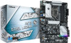
... ASRock's consistently stringent quality control. In case any modifications of the software and utilities. Chapter 4 contains the configuration guide of the motherboard and step-by-step installation guides. You may find the latest VGA cards and CPU support list on ASRock's website without notice. H570 Steel Legend Chapter 1 Introduction Thank you are using. Chapter 3 contains the operation guide of this motherboard, please visit our website for specific information about the model you for M.2 Socket (Optional) • 1 x I/O Panel...
... ASRock's consistently stringent quality control. In case any modifications of the software and utilities. Chapter 4 contains the configuration guide of the motherboard and step-by-step installation guides. You may find the latest VGA cards and CPU support list on ASRock's website without notice. H570 Steel Legend Chapter 1 Introduction Thank you are using. Chapter 3 contains the operation guide of this motherboard, please visit our website for specific information about the model you for M.2 Socket (Optional) • 1 x I/O Panel...

User Manual
Page 12
...-45 LAN Port with LED (ACT/LINK LED and SPEED LED) • HD Audio Jacks: Line in / Front Speaker / Microphone Storage • 6 x SATA3 6.0 Gb/s Connectors, support RAID (RAID 0, RAID 1, RAID 5, RAID 10, Intel Rapid Storage Technology 18), NCQ, AHCI and Hot Plug* * If M2_2 is occupied by a SATA-type M.2 device, SATA3_1 will be disabled. * If M2_2 is occupied by a PCIe-type M.2 device, SATA3_0 will be disabled. * If M2_3 is occupied by a SATA-type M.2 device, SATA3_2 will be disabled. English 4 Visual Network Usage Statistics - LAN...
...-45 LAN Port with LED (ACT/LINK LED and SPEED LED) • HD Audio Jacks: Line in / Front Speaker / Microphone Storage • 6 x SATA3 6.0 Gb/s Connectors, support RAID (RAID 0, RAID 1, RAID 5, RAID 10, Intel Rapid Storage Technology 18), NCQ, AHCI and Hot Plug* * If M2_2 is occupied by a SATA-type M.2 device, SATA3_1 will be disabled. * If M2_2 is occupied by a PCIe-type M.2 device, SATA3_0 will be disabled. * If M2_3 is occupied by a SATA-type M.2 device, SATA3_2 will be disabled. English 4 Visual Network Usage Statistics - LAN...

User Manual
Page 13
... M.2 PCI Express module up to Gen3 x4 (32 Gb/s)** ** Supports Intel® OptaneTM Technology ** Supports NVMe SSD as boot disks ** Supports ASRock U.2 Kit Connector • 1 x SPI TPM Header • 1 x Power LED and Speaker Header • 2 x RGB LED Headers * Support in total up to 12V/3A, 36W LED Strip • 2 x Addressable LED Headers * Support in total up to 5V/3A, 15W LED Strip • 1 x CPU Fan Connector (4-pin) * The CPU Fan Connector supports the CPU fan of maximum 1A (12W) fan power. • 1 x CPU/Water Pump Fan Connector (4-pin) (Smart Fan Speed Control) * The CPU...
... M.2 PCI Express module up to Gen3 x4 (32 Gb/s)** ** Supports Intel® OptaneTM Technology ** Supports NVMe SSD as boot disks ** Supports ASRock U.2 Kit Connector • 1 x SPI TPM Header • 1 x Power LED and Speaker Header • 2 x RGB LED Headers * Support in total up to 12V/3A, 36W LED Strip • 2 x Addressable LED Headers * Support in total up to 5V/3A, 15W LED Strip • 1 x CPU Fan Connector (4-pin) * The CPU Fan Connector supports the CPU fan of maximum 1A (12W) fan power. • 1 x CPU/Water Pump Fan Connector (4-pin) (Smart Fan Speed Control) * The CPU...
User Manual
Page 14
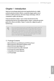
...; 2 x USB 3.2 Gen1 Headers (Support 4 USB 3.2 Gen1 ports) (ASMedia ASM1074 hub) (Supports ESD Protection) • 1 x Front Panel Type C USB 3.2 Gen2x2 Header (20 Gb/s) (Supports ESD Protection) BIOS Feature • AMI UEFI Legal BIOS with multilingual GUI support • ACPI 6.0 Compliant wake up events • SMBIOS 2.7 Support • CPU Core/Cache, CPU GT, DRAM, VCCIO, VCCSA, VCCST, VCCIN AUX, VPPM Voltage Multi-adjustment Hardware Monitor • Fan Tachometer: CPU, CPU/Water Pump, Chassis/Water Pump Fans • Quiet Fan (Auto adjust chassis fan speed by overclocking. We...
...; 2 x USB 3.2 Gen1 Headers (Support 4 USB 3.2 Gen1 ports) (ASMedia ASM1074 hub) (Supports ESD Protection) • 1 x Front Panel Type C USB 3.2 Gen2x2 Header (20 Gb/s) (Supports ESD Protection) BIOS Feature • AMI UEFI Legal BIOS with multilingual GUI support • ACPI 6.0 Compliant wake up events • SMBIOS 2.7 Support • CPU Core/Cache, CPU GT, DRAM, VCCIO, VCCSA, VCCST, VCCIN AUX, VPPM Voltage Multi-adjustment Hardware Monitor • Fan Tachometer: CPU, CPU/Water Pump, Chassis/Water Pump Fans • Quiet Fan (Auto adjust chassis fan speed by overclocking. We...

User Manual
Page 32
... p.7, No. 2) Front Panel Type C USB 3.2 Gen2x2 Header (20-pin F_USB31_TC_1) (see p.7, No. 13) 8 5 This motherboard provides an 8-pin ATX 12V power 4 1 connector. Do not plug the PCIe power cable to ATX12V2 is one Front Panel Type C USB 3.2 Gen2x2 Header on this motherboard. English 24 This header is for additional USB 3.2 Gen2x2 ports. To use a 4-pin ATX power supply, please plug it along Pin 1 and Pin 5. *Warning: Please make sure that the power cable connected is used for connecting a USB 3.2 Gen2x2 module for the CPU and not the graphics card.
... p.7, No. 2) Front Panel Type C USB 3.2 Gen2x2 Header (20-pin F_USB31_TC_1) (see p.7, No. 13) 8 5 This motherboard provides an 8-pin ATX 12V power 4 1 connector. Do not plug the PCIe power cable to ATX12V2 is one Front Panel Type C USB 3.2 Gen2x2 Header on this motherboard. English 24 This header is for additional USB 3.2 Gen2x2 ports. To use a 4-pin ATX power supply, please plug it along Pin 1 and Pin 5. *Warning: Please make sure that the power cable connected is used for connecting a USB 3.2 Gen2x2 module for the CPU and not the graphics card.

User Manual
Page 34
... power supply unit (PSU) can provide at least the minimum power your graphics card driver supports AMD CrossFireXTM technology. Please refer to PCIE3 slot. CrossFire Bridge Step 2 Connect two graphics cards by installing a CrossFire Bridge on the CrossFire Bridge Interconnects on the slots. Different CrossFireXTM cards may require different methods to three identical PCI Express x16 graphics cards. 1. Make sure that your system requires. 2.7 CrossFireXTM and Quad CrossFireXTM Operation Guide This motherboard supports...
... power supply unit (PSU) can provide at least the minimum power your graphics card driver supports AMD CrossFireXTM technology. Please refer to PCIE3 slot. CrossFire Bridge Step 2 Connect two graphics cards by installing a CrossFire Bridge on the CrossFire Bridge Interconnects on the slots. Different CrossFireXTM cards may require different methods to three identical PCI Express x16 graphics cards. 1. Make sure that your system requires. 2.7 CrossFireXTM and Quad CrossFireXTM Operation Guide This motherboard supports...
User Manual
Page 36
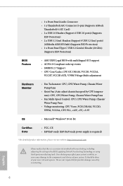
... AMD driver updates. The Catalyst Uninstaller is an optional download. Step 3 Install the required drivers and CATALYST Control Center then restart your graphics card and click Apply. Then select Enable AMD CrossFireX and click Apply. Step 5 In the left pane, click Performance and then AMD CrossFireXTM. English 28 Select the GPU number according to uninstall any VGA drivers installed in the Windows® system tray. 2.7.2 Driver Installation and Setup Step 1 Power...
... AMD driver updates. The Catalyst Uninstaller is an optional download. Step 3 Install the required drivers and CATALYST Control Center then restart your graphics card and click Apply. Then select Enable AMD CrossFireX and click Apply. Step 5 In the left pane, click Performance and then AMD CrossFireXTM. English 28 Select the GPU number according to uninstall any VGA drivers installed in the Windows® system tray. 2.7.2 Driver Installation and Setup Step 1 Power...
User Manual
Page 50
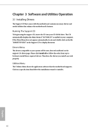
... display the menu. Drivers Menu The drivers compatible to your system will be auto-detected and listed on the file "ASRSETUP.EXE" in your CD-ROM drive. Running The Support CD To begin using the support CD, insert the CD into your computer. Chapter 3 Software and Utilities Operation 3.1 Installing Drivers The Support CD that comes with the motherboard contains necessary drivers and useful utilities that the motherboard supports. Therefore, the drivers you install can work properly. If the Main Menu...
... display the menu. Drivers Menu The drivers compatible to your system will be auto-detected and listed on the file "ASRSETUP.EXE" in your CD-ROM drive. Running The Support CD To begin using the support CD, insert the CD into your computer. Chapter 3 Software and Utilities Operation 3.1 Installing Drivers The Support CD that comes with the motherboard contains necessary drivers and useful utilities that the motherboard supports. Therefore, the drivers you install can work properly. If the Main Menu...
User Manual
Page 69
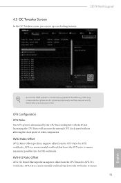
... 61 English H570 Steel Legend Because the UEFI software is determined by the CPU Ratio multiplied with the BCLK. AVX-512 Ratio Offset AVX-512 Ratio Offset specifies a negative offset from the CPU Ratio for AVX-512 workloads. Increasing the CPU Ratio will increase the internal CPU clock speed without affecting the clock speed of other components. 4.5 OC Tweaker Screen In the OC Tweaker screen, you...
... 61 English H570 Steel Legend Because the UEFI software is determined by the CPU Ratio multiplied with the BCLK. AVX-512 Ratio Offset AVX-512 Ratio Offset specifies a negative offset from the CPU Ratio for AVX-512 workloads. Increasing the CPU Ratio will increase the internal CPU clock speed without affecting the clock speed of other components. 4.5 OC Tweaker Screen In the OC Tweaker screen, you...

User Manual
Page 83
... SR-IOV capable PCIe Devices, this option Enables or Disables Single Root IO Virtualization Support. VT-d Intel® Virtualization Technology for Directed I/O helps your virtual machine monitor better utilize hardware by improving application compatibility and reliability, and providing additional levels of manageability, security, isolation, and I/O performance. 4.6.2 Chipset Configuration H570 Steel Legend Primary Graphics Adapter Select a primary VGA. DMI Link Speed Configure DMI Slot Link Speed. Above 4G Decoding Enable or disable 64bit capable Devices to be decoded...
... SR-IOV capable PCIe Devices, this option Enables or Disables Single Root IO Virtualization Support. VT-d Intel® Virtualization Technology for Directed I/O helps your virtual machine monitor better utilize hardware by improving application compatibility and reliability, and providing additional levels of manageability, security, isolation, and I/O performance. 4.6.2 Chipset Configuration H570 Steel Legend Primary Graphics Adapter Select a primary VGA. DMI Link Speed Configure DMI Slot Link Speed. Above 4G Decoding Enable or disable 64bit capable Devices to be decoded...

User Manual
Page 84
... PCH PCIE devices. PCH PCIE ASPM Support This option enables/disables the ASPM support for PCIE2. IGPU Multi-Monitor Select disable to enable onboard HD audio and 76 English Set to Auto to disable the integrated graphics when an external graphics card is allocated to keep the integrated graphics enabled at all times. PCIE ASPM Support This option enables/disables the ASPM support for enhanced PCI Express power saving in OS. Share Memory Configure the size of the DMI Link. PCI Express Native Control Select Enable for...
... PCH PCIE devices. PCH PCIE ASPM Support This option enables/disables the ASPM support for PCIE2. IGPU Multi-Monitor Select disable to enable onboard HD audio and 76 English Set to Auto to disable the integrated graphics when an external graphics card is allocated to keep the integrated graphics enabled at all times. PCIE ASPM Support This option enables/disables the ASPM support for enhanced PCI Express power saving in OS. Share Memory Configure the size of the DMI Link. PCI Express Native Control Select Enable for...

User Manual
Page 85
... to boot up when the power recovers. If [Power On] is selected, the power will start to enable or disable the onboard WAN device. Front Panel Enable/disable front panel HD audio. Restore on Onboard LED in the ACPI S5 state. Bluetooth Enable/disable the Bluetooth connectivity. Restore Onboard LED Default Restore Onboard LED default value. Onboard HDMI HD Audio Enable audio for power saving when the computer is installed. Deep Sleep Configure deep sleep mode for the onboard digital outputs. RGB LED This option enables/disables the RGB LED. 77 English H570 Steel Legend...
... to boot up when the power recovers. If [Power On] is selected, the power will start to enable or disable the onboard WAN device. Front Panel Enable/disable front panel HD audio. Restore on Onboard LED in the ACPI S5 state. Bluetooth Enable/disable the Bluetooth connectivity. Restore Onboard LED Default Restore Onboard LED default value. Onboard HDMI HD Audio Enable audio for power saving when the computer is installed. Deep Sleep Configure deep sleep mode for the onboard digital outputs. RGB LED This option enables/disables the RGB LED. 77 English H570 Steel Legend...

User Manual
Page 87
... Ridge Workaround for OSUP Enable or disable Titan Ridge Workaround for OSUP. Windows 10 Thunderbolt support Specify Windows 10 Thunderbolt support level. 4.6.4 Intel(R) Thunderbolt H570 Steel Legend Discrete Thunderbolt(TM) Support Enable or disable the Discrete Thunderbolt(TM) Support. Disabled: No OS native support. Thunderbolt Usb Support Enabled to allow booting from Bootable devices which are present behind Thunderbolt. Enabled: OS Native support only. Thunderbolt Boot Support Enabled to allow booting from Usb devices which are present behind...
... Ridge Workaround for OSUP Enable or disable Titan Ridge Workaround for OSUP. Windows 10 Thunderbolt support Specify Windows 10 Thunderbolt support level. 4.6.4 Intel(R) Thunderbolt H570 Steel Legend Discrete Thunderbolt(TM) Support Enable or disable the Discrete Thunderbolt(TM) Support. Disabled: No OS native support. Thunderbolt Usb Support Enabled to allow booting from Bootable devices which are present behind Thunderbolt. Enabled: OS Native support only. Thunderbolt Boot Support Enabled to allow booting from Usb devices which are present behind...
User Manual
Page 92
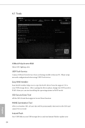
... Tool After you are having trouble with your PC. Please setup network configuration before using UEFI Tech Service. Instant Flash Save UEFI files in RAID mode. Easy RAID Installer Easy RAID Installer helps you to copy the RAID driver from the support CD to RAID, then you can start installing the operating system in your USB storage device and run Instant Flash to update your USB storage device. UEFI Tech Service Contact ASRock Tech Service if you Sanitize SSD, all user data will be permanently...
... Tool After you are having trouble with your PC. Please setup network configuration before using UEFI Tech Service. Instant Flash Save UEFI files in RAID mode. Easy RAID Installer Easy RAID Installer helps you to copy the RAID driver from the support CD to RAID, then you can start installing the operating system in your USB storage device and run Instant Flash to update your USB storage device. UEFI Tech Service Contact ASRock Tech Service if you Sanitize SSD, all user data will be permanently...
User Manual
Page 93
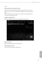
DHCP (Auto IP), Auto ASRock Internet Flash downloads and updates the latest UEFI firmware version from our servers for Internet Flash. UEFI Download Server Select a server to configure internet connection settings for you. H570 Steel Legend UEFI. Network Configuration Use this function. Internet Setting Enable or disable sound effects in your USB pen drive before using Internet Flash. *For BIOS backup and recovery purpose, it is recommended to plug in the setup utility. Internet Flash - Please setup network configuration before using this to download the UEFI firmware. 85...
DHCP (Auto IP), Auto ASRock Internet Flash downloads and updates the latest UEFI firmware version from our servers for Internet Flash. UEFI Download Server Select a server to configure internet connection settings for you. H570 Steel Legend UEFI. Network Configuration Use this function. Internet Setting Enable or disable sound effects in your USB pen drive before using Internet Flash. *For BIOS backup and recovery purpose, it is recommended to plug in the setup utility. Internet Flash - Please setup network configuration before using this to download the UEFI firmware. 85...
User Manual
Page 98
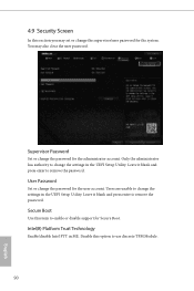
... may set or change the supervisor/user password for Secure Boot. Only the administrator has authority to remove the password. Leave it blank and press enter to enable or disable support for the system. Supervisor Password Set or change the password for the user account. Intel(R) Platform Trust Technology Enable/disable Intel PTT in the UEFI Setup Utility. Users are unable to use discrete TPM Module. 90 English Disable this option to change the settings in ME. 4.9 Security Screen...
... may set or change the supervisor/user password for Secure Boot. Only the administrator has authority to remove the password. Leave it blank and press enter to enable or disable support for the system. Supervisor Password Set or change the password for the user account. Intel(R) Platform Trust Technology Enable/disable Intel PTT in the UEFI Setup Utility. Users are unable to use discrete TPM Module. 90 English Disable this option to change the settings in ME. 4.9 Security Screen...
RAID Installation Guide
Page 7
... SATA Mode Selection to complete the process. STEP 2: Use ASRock Easy RAID Installer Easy RAID Installer can copy the RAID driver from a support CD to save the configuration changes and exit setup. Enter UEFI SETUP UTILITY Tool and highlight "Easy RAID Installer". STEP 1: Setting the BIOS RAID Items After installing the hard disk drives, please set RAID configuration. Press to your USB storage device with RAID functions, please follow the procedures below. STEP 3: Set RAID configuration Please refer to confirm the selection C. STEP 4: Install Windows® 10 64-bit...
... SATA Mode Selection to complete the process. STEP 2: Use ASRock Easy RAID Installer Easy RAID Installer can copy the RAID driver from a support CD to save the configuration changes and exit setup. Enter UEFI SETUP UTILITY Tool and highlight "Easy RAID Installer". STEP 1: Setting the BIOS RAID Items After installing the hard disk drives, please set RAID configuration. Press to your USB storage device with RAID functions, please follow the procedures below. STEP 3: Set RAID configuration Please refer to confirm the selection C. STEP 4: Install Windows® 10 64-bit...

RAID Installation Guide
Page 23
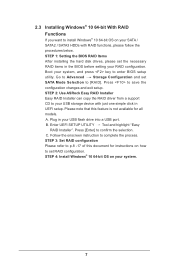
.... STEP 2: Install Windows® 10 64-bit OS Press to launch boot menu at system POST and choose the item "UEFI:" to use Windows® 10 64-bit. Installing Windows® on a HDD larger than 2TB in RAID mode Windows® 10 does not support HDD's larger than 2TB. STEP 1: Copy Intel® RAID drivers into a USB flash disk You can download the drivers from ASRock's website and unzip the files into a USB flash disk or copy the files from ASRock's motherboard support CD...
.... STEP 2: Install Windows® 10 64-bit OS Press to launch boot menu at system POST and choose the item "UEFI:" to use Windows® 10 64-bit. Installing Windows® on a HDD larger than 2TB in RAID mode Windows® 10 does not support HDD's larger than 2TB. STEP 1: Copy Intel® RAID drivers into a USB flash disk You can download the drivers from ASRock's website and unzip the files into a USB flash disk or copy the files from ASRock's motherboard support CD...
Intel Rapid Storage Guide
Page 13
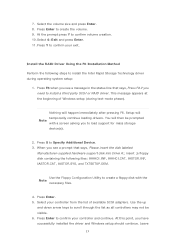
Select 4: Exit and press Enter. 11. Use the Floppy Configuration Utility to scroll through the list as all controllers may not be prompted Note with the Note necessary files. 4. Use the up and down arrow keys to create a floppy disk with a screen asking you have successfully installed the driver and Windows setup should continue. Press Enter to confirm volume creation. 10. Press F6 when you see a message in the...
Select 4: Exit and press Enter. 11. Use the Floppy Configuration Utility to scroll through the list as all controllers may not be prompted Note with the Note necessary files. 4. Use the up and down arrow keys to create a floppy disk with a screen asking you have successfully installed the driver and Windows setup should continue. Press Enter to confirm volume creation. 10. Press F6 when you see a message in the...


