
Quick Installation Guide
Page 2
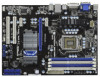
Motherboard Layout English 1 ATX 12V Power Connector (ATX12V1) 17 Dr. Debug (LED) 2 PS2_USB_PW1 Jumper 18 Clear CMOS Jumper (CLRCMOS1) 3 CPU Fan Connector (CPU_FAN1) 19 USB 2.0 Header (USB8_9, Blue) 4 1156-Pin CPU Socket 20 USB_PWR8_9 Jumper 5 2 x 240-pin DDR3 DIMM Slots 21 USB 2.0 Header (USB6_7, Blue) (Dual Channel: DDR3_A2, DDR3_B2, Blue) 22 USB_PWR6_7 Jumper 6 2 x 240-pin DDR3 DIMM Slots 23 System Panel Header (PANEL1, White) (Dual Channel: DDR3_A1, DDR3_B1, White) 24 Power LED Header (PLED1) 7 ATX Power Connector (ATXPWR1) 25 Chassis Speaker Header 8 16Mb SPI Flash (...
Motherboard Layout English 1 ATX 12V Power Connector (ATX12V1) 17 Dr. Debug (LED) 2 PS2_USB_PW1 Jumper 18 Clear CMOS Jumper (CLRCMOS1) 3 CPU Fan Connector (CPU_FAN1) 19 USB 2.0 Header (USB8_9, Blue) 4 1156-Pin CPU Socket 20 USB_PWR8_9 Jumper 5 2 x 240-pin DDR3 DIMM Slots 21 USB 2.0 Header (USB6_7, Blue) (Dual Channel: DDR3_A2, DDR3_B2, Blue) 22 USB_PWR6_7 Jumper 6 2 x 240-pin DDR3 DIMM Slots 23 System Panel Header (PANEL1, White) (Dual Channel: DDR3_A1, DDR3_B1, White) 24 Power LED Header (PLED1) 7 ATX Power Connector (ATXPWR1) 25 Chassis Speaker Header 8 16Mb SPI Flash (...
Quick Installation Guide
Page 3
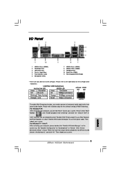
.... I/O Panel 1 USB 2.0 Ports (USB45) 2 VGA/D-Sub Port 3 LAN RJ-45 Port 4 Line In (Light Blue) 5 Front Speaker (Lime) 6 Microphone (Pink) 7 USB 2.0 Ports (USB01) 8 USB 2.0 Ports (USB23) 9 VGA/DVI-D Port 10 Serial Port (COM1) 11 PS/2 Keyboard Port (Purple) * There are allowed to select "Realtek HDA Primary output" to use front panel audio. Please select "Mixer ToolBox" , click "Enable playback multi-streaming", and click "ok". Then reboot your system. 3 ASRock H55iCafe Motherboard English LAN Port LED Indications Activity/Link LED SPEED LED Status...
.... I/O Panel 1 USB 2.0 Ports (USB45) 2 VGA/D-Sub Port 3 LAN RJ-45 Port 4 Line In (Light Blue) 5 Front Speaker (Lime) 6 Microphone (Pink) 7 USB 2.0 Ports (USB01) 8 USB 2.0 Ports (USB23) 9 VGA/DVI-D Port 10 Serial Port (COM1) 11 PS/2 Keyboard Port (Purple) * There are allowed to select "Realtek HDA Primary output" to use front panel audio. Please select "Mixer ToolBox" , click "Enable playback multi-streaming", and click "ok". Then reboot your system. 3 ASRock H55iCafe Motherboard English LAN Port LED Indications Activity/Link LED SPEED LED Status...
Quick Installation Guide
Page 4
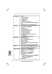
... user manual presented in , 30.5 cm x 22.4 cm) ASRock H55iCafe Quick Installation Guide ASRock H55iCafe Support CD 2 x Serial ATA (SATA) Data Cables (Optional) 1 x I/O Panel Shield 4 ASRock H55iCafe Motherboard English In case any modifications of the motherboard can be available on ASRock website as well. Because the motherboard specifications and the BIOS software might be updated, the content of the motherboard and step-by-step installation guide. This Quick Installation Guide contains introduction of this manual occur, the updated version will be subject to change...
... user manual presented in , 30.5 cm x 22.4 cm) ASRock H55iCafe Quick Installation Guide ASRock H55iCafe Support CD 2 x Serial ATA (SATA) Data Cables (Optional) 1 x I/O Panel Shield 4 ASRock H55iCafe Motherboard English In case any modifications of the motherboard can be available on ASRock website as well. Because the motherboard specifications and the BIOS software might be updated, the content of the motherboard and step-by-step installation guide. This Quick Installation Guide contains introduction of this manual occur, the updated version will be subject to change...

Quick Installation Guide
Page 5
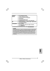
... Japan-made high-quality Conductive Polymer Capacitors) - V4 + 1 Power Phase Design - Intel® H55 - Dual Channel DDR3 Memory Technology (see CAUTION 3) - capacity of system memory: 16GB (see CAUTION 6) - 1 x PCI Express 2.0 x16 slot (blue @ x16 mode) - 2 x PCI Express 2.0 x1 slots (2.5GT/s) - 2 x PCI slots * Requires a Processor with Intel® Graphics Technology - Supports Intel® Extreme Memory Profile (XMP) (see CAUTION 5) - Pixel Shader 4.0, DirectX 10 - shared memory 1759MB (see CAUTION 7) - Supports Wake-On-LAN English 5 ASRock H55iCafe Motherboard
... Japan-made high-quality Conductive Polymer Capacitors) - V4 + 1 Power Phase Design - Intel® H55 - Dual Channel DDR3 Memory Technology (see CAUTION 3) - capacity of system memory: 16GB (see CAUTION 6) - 1 x PCI Express 2.0 x16 slot (blue @ x16 mode) - 2 x PCI Express 2.0 x1 slots (2.5GT/s) - 2 x PCI slots * Requires a Processor with Intel® Graphics Technology - Supports Intel® Extreme Memory Profile (XMP) (see CAUTION 5) - Pixel Shader 4.0, DirectX 10 - shared memory 1759MB (see CAUTION 7) - Supports Wake-On-LAN English 5 ASRock H55iCafe Motherboard
Quick Installation Guide
Page 6
... panel audio connector - 2 x USB 2.0 headers (support 4 USB 2.0 ports) (see CAUTION 14) - SMBIOS 2.3.1 Support - Drivers, Utilities, AntiVirus Software (Trial Version), ASRock Software Suite (CyberLink DVD Suite and Creative Sound Blaster X-Fi MB) (OEM and Trial Version) - Intelligent Energy Saver (see CAUTION 15) - ASRock U-COP (see CAUTION 11) - Supports jumperfree - T. (Intelligent Overclocking Technology) - Instant Boot - Good Night LED English 6 ASRock H55iCafe Motherboard Supports I /O Panel - 1 x PS/2 Keyboard Port - 1 x Serial Port: COM1 - 1 x VGA/D-Sub Port - 1 x VGA...
... panel audio connector - 2 x USB 2.0 headers (support 4 USB 2.0 ports) (see CAUTION 14) - SMBIOS 2.3.1 Support - Drivers, Utilities, AntiVirus Software (Trial Version), ASRock Software Suite (CyberLink DVD Suite and Creative Sound Blaster X-Fi MB) (OEM and Trial Version) - Intelligent Energy Saver (see CAUTION 15) - ASRock U-COP (see CAUTION 11) - Supports jumperfree - T. (Intelligent Overclocking Technology) - Instant Boot - Good Night LED English 6 ASRock H55iCafe Motherboard Supports I /O Panel - 1 x PS/2 Keyboard Port - 1 x Serial Port: COM1 - 1 x VGA/D-Sub Port - 1 x VGA...
Quick Installation Guide
Page 7
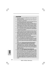
... and devices of your own risk and expense. English 7 ASRock H55iCafe Motherboard EuP Ready (EuP ready power supply is required) (see CAUTION 16) * For detailed product information, please visit our website: http://www.asrock.com WARNING Please realize that there is a certain risk involved with overclocking, including adjusting the setting in the BIOS, applying Untied Overclocking Technology, or using the thirdparty overclocking tools. CPU Fan Multi-Speed Control - Voltage Monitoring...
... and devices of your own risk and expense. English 7 ASRock H55iCafe Motherboard EuP Ready (EuP ready power supply is required) (see CAUTION 16) * For detailed product information, please visit our website: http://www.asrock.com WARNING Please realize that there is a certain risk involved with overclocking, including adjusting the setting in the BIOS, applying Untied Overclocking Technology, or using the thirdparty overclocking tools. CPU Fan Multi-Speed Control - Voltage Monitoring...
Quick Installation Guide
Page 8
... update your USB flash drive, floppy disk or hard drive, then you to access ASRock Instant Flash. You can press key during the POST or press key to BIOS setup menu to update system BIOS without entering operating systems first like MS-DOS or Windows®. Just launch this utility, you implement Dual Channel Memory Technology, make sure to SATAII mode. Intel® CoreTM i3 and Pentium® G6950 processors do not support Intel® Turbo Boost Technology. 2. About the setting...
... update your USB flash drive, floppy disk or hard drive, then you to access ASRock Instant Flash. You can press key during the POST or press key to BIOS setup menu to update system BIOS without entering operating systems first like MS-DOS or Windows®. Just launch this utility, you implement Dual Channel Memory Technology, make sure to SATAII mode. Intel® CoreTM i3 and Pentium® G6950 processors do not support Intel® Turbo Boost Technology. 2. About the setting...
Quick Installation Guide
Page 9
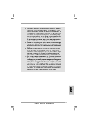
... details. 9 ASRock H55iCafe Motherboard English For EuP ready power supply selection, we recommend you can only be shared and worked on the motherboard functions properly and unplug the power cord, then plug it is higher than the recommended CPU bus frequencies may cause the instability of overclocking settings. 13. OC DNA literally tells you install the PC system. 16. Your friends then can load the OC...
... details. 9 ASRock H55iCafe Motherboard English For EuP ready power supply selection, we recommend you can only be shared and worked on the motherboard functions properly and unplug the power cord, then plug it is higher than the recommended CPU bus frequencies may cause the instability of overclocking settings. 13. OC DNA literally tells you install the PC system. 16. Your friends then can load the OC...
Quick Installation Guide
Page 12
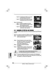
... CPU Fan and Heatsink For proper installation, please kindly refer to install and lock. Carefully place the CPU into the socket by using a purely vertical motion. Close the socket: Step 4-1. Step 4-3. Align fasteners with remaining fasteners. Secure excess cable with tie-wrap to ensure cable does not interfere with thumb to the instruction manuals of IHS on load plate, engage the load lever. English 12 ASRock H55iCafe Motherboard...
... CPU Fan and Heatsink For proper installation, please kindly refer to install and lock. Carefully place the CPU into the socket by using a purely vertical motion. Close the socket: Step 4-1. Step 4-3. Align fasteners with remaining fasteners. Secure excess cable with tie-wrap to ensure cable does not interfere with thumb to the instruction manuals of IHS on load plate, engage the load lever. English 12 ASRock H55iCafe Motherboard...
Quick Installation Guide
Page 15
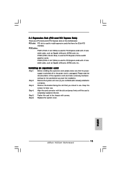
... motherboard is used for PCI Express x16 lane width graphics cards. Align the card connector with x1 lane width cards, such as Gigabit LAN card, SATA2 card, etc. PCIE slots: PCIE1 (PCIE x1 slot; Before installing the expansion card, please make necessary hardware settings for PCI Express cards with the slot and press firmly until the card is unplugged. White) is used to install expansion cards that have the 32-bit PCI interface. Remove the bracket facing the slot that the power supply...
... motherboard is used for PCI Express x16 lane width graphics cards. Align the card connector with x1 lane width cards, such as Gigabit LAN card, SATA2 card, etc. PCIE slots: PCIE1 (PCIE x1 slot; Before installing the expansion card, please make necessary hardware settings for PCI Express cards with the slot and press firmly until the card is unplugged. White) is used to install expansion cards that have the 32-bit PCI interface. Remove the bracket facing the slot that the power supply...
Quick Installation Guide
Page 16
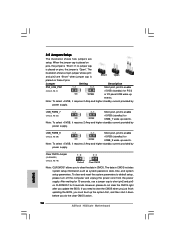
... on pins, the jumper is placed on CLRCMOS1 for 15 seconds, use a jumper cap to default setup, please turn off the computer and unplug the power cord from the power supply. Jumper Setting Description PS2_USB_PW1 Short pin2, pin3 to enable (see p.2, No. 2) +5VSB (standby) for PS/2 or I/O panel USB wake up events. If no jumper cap is "Open". USB_PWR6_7 Short pin2, pin3 to clear the CMOS when you just finish updating the BIOS...
... on pins, the jumper is placed on CLRCMOS1 for 15 seconds, use a jumper cap to default setup, please turn off the computer and unplug the power cord from the power supply. Jumper Setting Description PS2_USB_PW1 Short pin2, pin3 to enable (see p.2, No. 2) +5VSB (standby) for PS/2 or I/O panel USB wake up events. If no jumper cap is "Open". USB_PWR6_7 Short pin2, pin3 to clear the CMOS when you just finish updating the BIOS...

Quick Installation Guide
Page 17
... allows up to the SATA / SATAII hard disk or the SATAII connector on this motherboard. Infrared Module Header (5-pin IR1) (see p.2, No. 15) These six Serial ATAII (SATAII) connectors support SATA data cables for internal storage devices. English 17 ASRock H55iCafe Motherboard SATAII_6 SATAII_4 SATAII_2 SATAII_5 SATAII_3 SATAII_1 Serial ATA (SATA) Data Cable (Optional) USB 2.0 Headers (9-pin USB8_9) (see p.2 No. 19) (9-pin USB6_7) (see p.2 No. 21) Either end of the motherboard! Each USB 2.0 header can be connected to 3.0 Gb/s data...
... allows up to the SATA / SATAII hard disk or the SATAII connector on this motherboard. Infrared Module Header (5-pin IR1) (see p.2, No. 15) These six Serial ATAII (SATAII) connectors support SATA data cables for internal storage devices. English 17 ASRock H55iCafe Motherboard SATAII_6 SATAII_4 SATAII_2 SATAII_5 SATAII_3 SATAII_1 Serial ATA (SATA) Data Cable (Optional) USB 2.0 Headers (9-pin USB8_9) (see p.2 No. 19) (9-pin USB6_7) (see p.2 No. 21) Either end of the motherboard! Each USB 2.0 header can be connected to 3.0 Gb/s data...
Quick Installation Guide
Page 18
... front panel functions. C. Enter Advanced Settings, and then select Chipset Configuration. For Windows® XP / XP 64-bit OS: Please select "Front Mic" as below: A. English 18 ASRock H55iCafe Motherboard For Windows® 7 / 7 64-bit / VistaTM / VistaTM 64-bit OS: Go to the front panel audio header as default record device. Enter BIOS Setup Utility. Please follow the instruction in our manual and chassis manual to OUT2_L. Connect Audio_R (RIN) to OUT2_R and Audio_L (LIN) to install your...
... front panel functions. C. Enter Advanced Settings, and then select Chipset Configuration. For Windows® XP / XP 64-bit OS: Please select "Front Mic" as below: A. English 18 ASRock H55iCafe Motherboard For Windows® 7 / 7 64-bit / VistaTM / VistaTM 64-bit OS: Go to the front panel audio header as default record device. Enter BIOS Setup Utility. Please follow the instruction in our manual and chassis manual to OUT2_L. Connect Audio_R (RIN) to OUT2_R and Audio_L (LIN) to install your...

Quick Installation Guide
Page 19
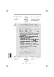
... the black wire to the ground pin. The LED is operating. CPU Fan Connector (4-pin CPU_FAN1) (see p.2 No. 3) 1 2 3 4 Please connect a CPU fan cable to this header to indicate system power status. To use the 20-pin ATX power supply, please plug your power supply along with Pin 1 and Pin 13. 20-Pin ATX Power Supply Installation 1 ASRock H55iCafe Motherboard 13 19 English The LED is on this motherboard provides 4-Pin CPU fan (Quiet Fan) support, the 3-Pin CPU fan still can still work successfully even without the fan speed control function. Chassis Speaker Header (4-pin SPEAKER...
... the black wire to the ground pin. The LED is operating. CPU Fan Connector (4-pin CPU_FAN1) (see p.2 No. 3) 1 2 3 4 Please connect a CPU fan cable to this header to indicate system power status. To use the 20-pin ATX power supply, please plug your power supply along with Pin 1 and Pin 13. 20-Pin ATX Power Supply Installation 1 ASRock H55iCafe Motherboard 13 19 English The LED is on this motherboard provides 4-Pin CPU fan (Quiet Fan) support, the 3-Pin CPU fan still can still work successfully even without the fan speed control function. Chassis Speaker Header (4-pin SPEAKER...
Quick Installation Guide
Page 21
... initialization code sets up from ROM to lower system memory and control is given to checkpoint E0. The following table describes the type of RAM. Early super I/O initialization is tested. Verify that flat mode is disabled. English 21 ASRock H55iCafe Motherboard 2.7 Dr. Debug Dr. Debug is used to flat mode with 4GB limit and GA20 enabled. Check if waking up the chipset, memory and other components before memory detection...
... initialization code sets up from ROM to lower system memory and control is given to checkpoint E0. The following table describes the type of RAM. Early super I/O initialization is tested. Verify that flat mode is disabled. English 21 ASRock H55iCafe Motherboard 2.7 Dr. Debug Dr. Debug is used to flat mode with 4GB limit and GA20 enabled. Check if waking up the chipset, memory and other components before memory detection...
Quick Installation Guide
Page 22
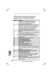
Also initialize BIOS modules on KBC. Verify CMOS checksum manually by reading storage area. Early CPU Init Start - Detects the presence of chipset registers. Early POST initialization of Keyboard in KBC port. Initialize language and font modules for system timer interrupt. ASRock H55iCafe Motherboard English Initialize BIOS, POST, Runtime data area. Enable IRQ-0 in the Kernel Variable "wCMOSFlags." Disable Cache - See DIM Code Checkpoints section of the BIOS: Checkpoint 03...
Also initialize BIOS modules on KBC. Verify CMOS checksum manually by reading storage area. Early CPU Init Start - Detects the presence of chipset registers. Early POST initialization of Keyboard in KBC port. Initialize language and font modules for system timer interrupt. ASRock H55iCafe Motherboard English Initialize BIOS, POST, Runtime data area. Enable IRQ-0 in the Kernel Variable "wCMOSFlags." Disable Cache - See DIM Code Checkpoints section of the BIOS: Checkpoint 03...
Quick Installation Guide
Page 23
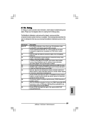
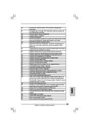
... errors encountered during POST. 85 Display errors to limit memory test. Allocates memory for error. 87 Execute BIOS setup if needed before boot, which includes the programming of chipset registers. Prepares the runtime language module. A2 Takes care of system management interrupt. A0 Check boot password if installed. Disables the system configuration display if needed . AC End of POST initialization of the MTRR's. English 23 ASRock H55iCafe Motherboard A7 Displays the system configuration screen...
... errors encountered during POST. 85 Display errors to limit memory test. Allocates memory for error. 87 Execute BIOS setup if needed before boot, which includes the programming of chipset registers. Prepares the runtime language module. A2 Takes care of system management interrupt. A0 Check boot password if installed. Disables the system configuration display if needed . AC End of POST initialization of the MTRR's. English 23 ASRock H55iCafe Motherboard A7 Displays the system configuration screen...
Quick Installation Guide
Page 24
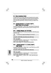
...your optical drive first. A. STEP 2: Install Windows® 7 / 7 64-bit / VistaTM / VistaTM 64-bit OS on your system. 24 ASRock H55iCafe Motherboard English Then, the drivers compatible to [IDE]. Using SATA / SATAII HDDs without NCQ function (IDE mode) STEP 1: Set up BIOS. A. Using SATA / SATAII HDDs without NCQ function (IDE mode) STEP 1: Set up BIOS. Enter BIOS SETUP UTILITY Advanced screen Storage Configuration. B. B. Enter BIOS SETUP UTILITY Advanced screen Storage Configuration. Set the option "SATA Operation Mode" to install those required drivers. AHCI mode is...
...your optical drive first. A. STEP 2: Install Windows® 7 / 7 64-bit / VistaTM / VistaTM 64-bit OS on your system. 24 ASRock H55iCafe Motherboard English Then, the drivers compatible to [IDE]. Using SATA / SATAII HDDs without NCQ function (IDE mode) STEP 1: Set up BIOS. A. Using SATA / SATAII HDDs without NCQ function (IDE mode) STEP 1: Set up BIOS. Enter BIOS SETUP UTILITY Advanced screen Storage Configuration. B. B. Enter BIOS SETUP UTILITY Advanced screen Storage Configuration. Set the option "SATA Operation Mode" to install those required drivers. AHCI mode is...
Quick Installation Guide
Page 25
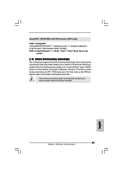
...10 Untied Overclocking Technology This motherboard supports Untied Overclocking Technology, which means during overclocking, but PCI / PCIE buses are in the fixed mode so that FSB can operate under a more stable overclocking environment. B. Before you apply Untied Overclocking Technology. 25 ASRock H55iCafe Motherboard English Therefore, CPU FSB is untied during overclocking, FSB enjoys better margin due to [AHCI]. Set the option "SATA Operation Mode" to fixed PCI / PCIE buses. A. Enter BIOS SETUP UTILITY Advanced screen Storage Configuration. Using SATA / SATAII HDDs with NCQ...
...10 Untied Overclocking Technology This motherboard supports Untied Overclocking Technology, which means during overclocking, but PCI / PCIE buses are in the fixed mode so that FSB can operate under a more stable overclocking environment. B. Before you apply Untied Overclocking Technology. 25 ASRock H55iCafe Motherboard English Therefore, CPU FSB is untied during overclocking, FSB enjoys better margin due to [AHCI]. Set the option "SATA Operation Mode" to fixed PCI / PCIE buses. A. Enter BIOS SETUP UTILITY Advanced screen Storage Configuration. Using SATA / SATAII HDDs with NCQ...
Quick Installation Guide
Page 26
... the User Manual (PDF file) contained in your CDROM drive. If you start up the computer, please press during the Power-On-Self-Test (POST) to select among the predetermined choices. Software Support CD information This motherboard supports various Microsoft® Windows® operating systems: 7 / 7 64-bit / VistaTM / VistaTM 64-bit / XP / XP 64-bit. If the Main Menu does not appear automatically, locate and doubleclick on the motherboard stores BIOS Setup Utility. BIOS...
... the User Manual (PDF file) contained in your CDROM drive. If you start up the computer, please press during the Power-On-Self-Test (POST) to select among the predetermined choices. Software Support CD information This motherboard supports various Microsoft® Windows® operating systems: 7 / 7 64-bit / VistaTM / VistaTM 64-bit / XP / XP 64-bit. If the Main Menu does not appear automatically, locate and doubleclick on the motherboard stores BIOS Setup Utility. BIOS...


