
User Manual
Page 5
... Contents 1 1.2 Specifications 2 1.3 Motherboard Layout 6 1.4 I/O Panel 9 Chapter 2 Installation 11 2.1 Installing the CPU 12 2.2 Installing the CPU Fan and Heatsink 15 2.3 Installing Memory Modules (DIMM) 16 2.4 Expansion Slots (PCI Express Slots) 18 2.5 Jumpers Setup 19 2.6 Onboard Headers and Connectors 20 Chapter 3 Software and Utilities Operation 24 3.1 Installing Drivers 24 3.2 ASRock Motherboard Utility (A-Tuning) 25 3.2.1 Installing ASRock Motherboard Utility (A-Tuning) 25 3.2.2 Using ASRock Motherboard Utility (A-Tuning) 25 3.3 ASRock Live Update & APP...
... Contents 1 1.2 Specifications 2 1.3 Motherboard Layout 6 1.4 I/O Panel 9 Chapter 2 Installation 11 2.1 Installing the CPU 12 2.2 Installing the CPU Fan and Heatsink 15 2.3 Installing Memory Modules (DIMM) 16 2.4 Expansion Slots (PCI Express Slots) 18 2.5 Jumpers Setup 19 2.6 Onboard Headers and Connectors 20 Chapter 3 Software and Utilities Operation 24 3.1 Installing Drivers 24 3.2 ASRock Motherboard Utility (A-Tuning) 25 3.2.1 Installing ASRock Motherboard Utility (A-Tuning) 25 3.2.2 Using ASRock Motherboard Utility (A-Tuning) 25 3.3 ASRock Live Update & APP...

User Manual
Page 7
... change without further notice. Chapter 4 contains the configuration guide of the software and utilities. H510M-HDV R2.0 H510M-HVS R2.0 Chapter 1 Introduction Thank you are using. In this documentation will be subject to quality and endurance. In case any modifications of the motherboard and step-by-step installation guides. You may find the latest VGA cards and CPU support list on ASRock's website without notice. Because the motherboard specifications and the BIOS software might be updated...
... change without further notice. Chapter 4 contains the configuration guide of the software and utilities. H510M-HDV R2.0 H510M-HVS R2.0 Chapter 1 Introduction Thank you are using. In this documentation will be subject to quality and endurance. In case any modifications of the motherboard and step-by-step installation guides. You may find the latest VGA cards and CPU support list on ASRock's website without notice. Because the motherboard specifications and the BIOS software might be updated...

User Manual
Page 9
..., Deep Color (12bpc), xvYCC and HBR (High Bit Rate Audio) with HDMI 2.0 Port (Compliant HDMI monitor is required) • Supports HDCP 2.3 with DVI-D and HDMI 2.0 Ports H510M-HVS R2.0: • Dual graphics output: support HDMI and D-Sub ports by independent display controllers • Supports HDMI 2.0 with max. Audio LAN H510M-HDV R2.0 H510M-HVS R2.0 • Graphics, Media & Compute: Microsoft DirectX 12, OpenGL 4.5, Intel® Built In Visuals, Intel® Quick Sync Video, Hybrid / Switchable Graphics, OpenCL 2.1 • Display & Content Security: Rec. 2020 (Wide...
..., Deep Color (12bpc), xvYCC and HBR (High Bit Rate Audio) with HDMI 2.0 Port (Compliant HDMI monitor is required) • Supports HDCP 2.3 with DVI-D and HDMI 2.0 Ports H510M-HVS R2.0: • Dual graphics output: support HDMI and D-Sub ports by independent display controllers • Supports HDMI 2.0 with max. Audio LAN H510M-HDV R2.0 H510M-HVS R2.0 • Graphics, Media & Compute: Microsoft DirectX 12, OpenGL 4.5, Intel® Built In Visuals, Intel® Quick Sync Video, Hybrid / Switchable Graphics, OpenCL 2.1 • Display & Content Security: Rec. 2020 (Wide...

User Manual
Page 10
... USB 2.0 Ports (Supports ESD Protection) • 1 x RJ-45 LAN Port with LED (ACT/LINK LED and SPEED LED) • HD Audio Jacks: Line in / Front Speaker / Microphone H510M-HDV R2.0: • 1 x D-Sub Port • 1 x DVI-D Port • 1 x HDMI Port H510M-HVS R2.0: • 1 x D-Sub Port • 1 x HDMI Port Storage • 4 x SATA3 6.0 Gb/s Connectors, support Intel Rapid Storage Technology 18, NCQ, AHCI and Hot Plug Connector • 1 x SPI TPM Header • 1 x Chassis Intrusion and Speaker Header • 1 x CPU Fan Connector (4-pin) * The CPU Fan Connector supports the CPU fan of...
... USB 2.0 Ports (Supports ESD Protection) • 1 x RJ-45 LAN Port with LED (ACT/LINK LED and SPEED LED) • HD Audio Jacks: Line in / Front Speaker / Microphone H510M-HDV R2.0: • 1 x D-Sub Port • 1 x DVI-D Port • 1 x HDMI Port H510M-HVS R2.0: • 1 x D-Sub Port • 1 x HDMI Port Storage • 4 x SATA3 6.0 Gb/s Connectors, support Intel Rapid Storage Technology 18, NCQ, AHCI and Hot Plug Connector • 1 x SPI TPM Header • 1 x Chassis Intrusion and Speaker Header • 1 x CPU Fan Connector (4-pin) * The CPU Fan Connector supports the CPU fan of...
User Manual
Page 11
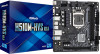
... support • ACPI 6.0 Compliant wake up events • SMBIOS 2.7 Support • CPU Core/Cache, CPU GT, VCCSA, DRAM, VCCIO, CPU Standby, VCCIN AUX Voltage Multi-adjustment • Fan Tachometer: CPU, Chassis/Water Pump Fans • Quiet Fan (Auto adjust chassis fan speed by overclocking. It should be done at your system. H510M-HDV R2.0 H510M-HVS R2.0 BIOS Feature Hardware Monitor OS Certifications • AMI UEFI Legal BIOS with overclocking, including adjusting the setting in the BIOS, applying Untied Overclocking Technology, or using third-party overclocking...
... support • ACPI 6.0 Compliant wake up events • SMBIOS 2.7 Support • CPU Core/Cache, CPU GT, VCCSA, DRAM, VCCIO, CPU Standby, VCCIN AUX Voltage Multi-adjustment • Fan Tachometer: CPU, Chassis/Water Pump Fans • Quiet Fan (Auto adjust chassis fan speed by overclocking. It should be done at your system. H510M-HDV R2.0 H510M-HVS R2.0 BIOS Feature Hardware Monitor OS Certifications • AMI UEFI Legal BIOS with overclocking, including adjusting the setting in the BIOS, applying Untied Overclocking Technology, or using third-party overclocking...

User Manual
Page 14
No. Description 1 ATX 12V Power Connector (ATX12V1) 2 CPU Fan Connector (CPU_FAN1) 3 2 x 288-pin DDR4 DIMM Slots (DDR4_A1, DDR4_B1) 4 Chassis/Waterpump Fan Connector (CHA_FAN1/WP) 5 ATX Power Connector (ATXPWR1) 6 USB 3.2 Gen1 Header (USB3_3_4) 7 USB 2.0 Header (USB_5_6) 8 SATA3 Connector (SATA3_3) (Upper), SATA3 Connector (SATA3_2) (Lower) 9 SATA3 Connector (SATA3_1) 10 SATA3 Connector (SATA3_0) 11 System Panel Header (PANEL1) 12 SPI TPM Header (SPI_TPM_J1) 13 Chassis Intrusion and Speaker Header (SPK_CI1) 14 Clear CMOS Jumper (CLRMOS1) 15 Front Panel Audio Header (HD_AUDIO1) 8 English
No. Description 1 ATX 12V Power Connector (ATX12V1) 2 CPU Fan Connector (CPU_FAN1) 3 2 x 288-pin DDR4 DIMM Slots (DDR4_A1, DDR4_B1) 4 Chassis/Waterpump Fan Connector (CHA_FAN1/WP) 5 ATX Power Connector (ATXPWR1) 6 USB 3.2 Gen1 Header (USB3_3_4) 7 USB 2.0 Header (USB_5_6) 8 SATA3 Connector (SATA3_3) (Upper), SATA3 Connector (SATA3_2) (Lower) 9 SATA3 Connector (SATA3_1) 10 SATA3 Connector (SATA3_0) 11 System Panel Header (PANEL1) 12 SPI TPM Header (SPI_TPM_J1) 13 Chassis Intrusion and Speaker Header (SPK_CI1) 14 Clear CMOS Jumper (CLRMOS1) 15 Front Panel Audio Header (HD_AUDIO1) 8 English

User Manual
Page 17
Failure to do so may damage the motherboard. 11 English H510M-HDV R2.0 H510M-HVS R2.0 Chapter 2 Installation This is a Micro ATX form factor motherboard. Also remember to the chassis, please do not touch the ICs. • Whenever you install motherboard components or change any components, place them on a carpet. Before you install the motherboard, study the configuration of the following precautions before you uninstall any motherboard settings. • Make...
Failure to do so may damage the motherboard. 11 English H510M-HDV R2.0 H510M-HVS R2.0 Chapter 2 Installation This is a Micro ATX form factor motherboard. Also remember to the chassis, please do not touch the ICs. • Whenever you install motherboard components or change any components, place them on a carpet. Before you install the motherboard, study the configuration of the following precautions before you uninstall any motherboard settings. • Make...

User Manual
Page 24
... settings for PCI Express x1 lane width cards. PCIE2 (PCIe 4.0 x16 slot) is used for the card before you start the installation. 2.4 Expansion Slots (PCI Express Slots) There are 2 PCI Express slots slot on the motherboard. Please read the documentation of the expansion card and make sure that the power supply is switched off or the power cord is used for PCI Express x16 lane width graphics cards. 10th Gen Intel® CoreTM Processors: PCIE1 (PCIe 3.0 x1 slot) is unplugged. PCIE2 (PCIe 3.0 x16 slot...
... settings for PCI Express x1 lane width cards. PCIE2 (PCIe 4.0 x16 slot) is used for the card before you start the installation. 2.4 Expansion Slots (PCI Express Slots) There are 2 PCI Express slots slot on the motherboard. Please read the documentation of the expansion card and make sure that the power supply is switched off or the power cord is used for PCI Express x16 lane width graphics cards. 10th Gen Intel® CoreTM Processors: PCIE1 (PCIe 3.0 x1 slot) is unplugged. PCIE2 (PCIe 3.0 x16 slot...

User Manual
Page 25
... 15 seconds, use a jumper cap to short the pins on the pins, the jumper is placed on CLRMOS1 for 5 seconds. However, please do the clear-CMOS action. Please adjust the BIOS option "Clear Status" to default setup, please turn off the computer and unplug the power cord from the power supply. English 19 If you to clear the CMOS when you just finish updating the BIOS, you must boot up the system...
... 15 seconds, use a jumper cap to short the pins on the pins, the jumper is placed on CLRMOS1 for 5 seconds. However, please do the clear-CMOS action. Please adjust the BIOS option "Clear Status" to default setup, please turn off the computer and unplug the power cord from the power supply. English 19 If you to clear the CMOS when you just finish updating the BIOS, you must boot up the system...

User Manual
Page 27
... ports. MIC2_L 1 English 21 USB 2.0 Header (9-pin USB_5_6) (see p.6, 7, No. 6) Vbus IntA_PA_SSRXIntA_PA_SSRX+ GND IntA_PA_SSTXIntA_PA_SSTX+ GND IntA_PA_DIntA_PA_D+ Vbus IntA_PB_SSRXIntA_PB_SSRX+ GND IntA_PB_SSTXIntA_PB_SSTX+ GND IntA_PB_DIntA_PB_D+ Dummy 1 There is one USB2.0 header on this motherboard. Front Panel Audio Header GN D (9-pin HD_AUDIO1) (see p.6, 7, No. 9) SATA3_0 SATA3_3 SATA3_1 SATA3_2 These four SATA3 connectors support SATA data cables for J_SENSE connecting audio devices OUT2_R MIC2_R to 6.0 Gb/s data transfer rate. H510M-HDV R2.0 H510M-HVS R2.0 Serial...
... ports. MIC2_L 1 English 21 USB 2.0 Header (9-pin USB_5_6) (see p.6, 7, No. 6) Vbus IntA_PA_SSRXIntA_PA_SSRX+ GND IntA_PA_SSTXIntA_PA_SSTX+ GND IntA_PA_DIntA_PA_D+ Vbus IntA_PB_SSRXIntA_PB_SSRX+ GND IntA_PB_SSTXIntA_PB_SSTX+ GND IntA_PB_DIntA_PB_D+ Dummy 1 There is one USB2.0 header on this motherboard. Front Panel Audio Header GN D (9-pin HD_AUDIO1) (see p.6, 7, No. 9) SATA3_0 SATA3_3 SATA3_1 SATA3_2 These four SATA3 connectors support SATA data cables for J_SENSE connecting audio devices OUT2_R MIC2_R to 6.0 Gb/s data transfer rate. H510M-HDV R2.0 H510M-HVS R2.0 Serial...
User Manual
Page 29
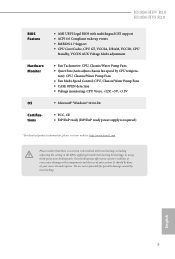
... PCIe power cable to this connector. H510M-HDV R2.0 H510M-HVS R2.0 ATX 12V Power Connector (8-pin ATX12V1) (see p.6, 7, No. 1) SPI TPM Header (13-pin SPI_TPM_J1) (see p.6, 7, No. 12) 8 5 This motherboard provides a 8-pin ATX 12V power connector. SPI_DQ3 +3.3V Dummy CLK SPI_MOSI RST# TPM_PIRQ 1 SPI_TPM_CS# GND RSMRST# SPI_MISO SPI_CS0 SPI_DQ2 This connector supports SPI Trusted Platform Module (TPM) system, which can securely store keys, digital certificates, passwords, and data. To use a 4 1 4-pin ATX power supply, please plug it along Pin 1 and Pin...
... PCIe power cable to this connector. H510M-HDV R2.0 H510M-HVS R2.0 ATX 12V Power Connector (8-pin ATX12V1) (see p.6, 7, No. 1) SPI TPM Header (13-pin SPI_TPM_J1) (see p.6, 7, No. 12) 8 5 This motherboard provides a 8-pin ATX 12V power connector. SPI_DQ3 +3.3V Dummy CLK SPI_MOSI RST# TPM_PIRQ 1 SPI_TPM_CS# GND RSMRST# SPI_MISO SPI_CS0 SPI_DQ2 This connector supports SPI Trusted Platform Module (TPM) system, which can securely store keys, digital certificates, passwords, and data. To use a 4 1 4-pin ATX power supply, please plug it along Pin 1 and Pin...
User Manual
Page 30
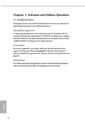
..., locate and double click on a specific item then follow the order from top to bottom to your computer. Therefore, the drivers you install can work properly. Click on the file "ASRSETUP.EXE" in your system will be auto-detected and listed on the support CD driver page. Utilities Menu The Utilities Menu shows the application software that enhance the motherboard's features. The CD automatically displays the Main Menu if...
..., locate and double click on a specific item then follow the order from top to bottom to your computer. Therefore, the drivers you install can work properly. Click on the file "ASRSETUP.EXE" in your system will be auto-detected and listed on the support CD driver page. Utilities Menu The Utilities Menu shows the application software that enhance the motherboard's features. The CD automatically displays the Main Menu if...
User Manual
Page 43
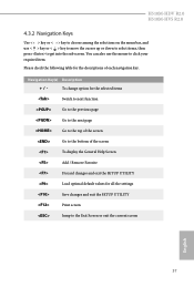
... the settings Save changes and exit the SETUP UTILITY Print screen Jump to the Exit Screen or exit the current screen English 37 You can also use < > key or < > key to move the cursor up or down to select items, then press to get into the sub screen. H510M-HDV R2.0 H510M-HVS R2.0 4.3.2 Navigation Keys Use < > key or < > key to choose among the selections on the menu bar, and use the...
... the settings Save changes and exit the SETUP UTILITY Print screen Jump to the Exit Screen or exit the current screen English 37 You can also use < > key or < > key to move the cursor up or down to select items, then press to get into the sub screen. H510M-HDV R2.0 H510M-HVS R2.0 4.3.2 Navigation Keys Use < > key or < > key to choose among the selections on the menu bar, and use the...
User Manual
Page 45
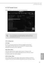
... UEFI setup screens and descriptions are for AVX workloads. Increasing the CPU Ratio will increase the internal CPU clock speed without affecting the clock speed of other components. AVX-512 Ratio Offset AVX-512 Ratio Offset specifies a negative offset from the CPU Ratio for reference purpose only, and they may not exactly match what you can set up overclocking features. H510M-HDV R2.0 H510M-HVS R2.0 Because the UEFI software...
... UEFI setup screens and descriptions are for AVX workloads. Increasing the CPU Ratio will increase the internal CPU clock speed without affecting the clock speed of other components. AVX-512 Ratio Offset AVX-512 Ratio Offset specifies a negative offset from the CPU Ratio for reference purpose only, and they may not exactly match what you can set up overclocking features. H510M-HDV R2.0 H510M-HVS R2.0 Because the UEFI software...

User Manual
Page 58
..., isolation, and I/O performance. Above 4G Decoding Enable or disable 64bit capable Devices to be decoded in Above 4G Address Space (only if the system supports 64 bit PCI decoding). VT-d Intel® Virtualization Technology for PCIE1. 52 English DMI Link Speed Configure DMI Slot Link Speed. Auto mode is optimizing for overclocking. SR-IOV Support If system has SR-IOV capable PCIe Devices, this option Enables or Disables Single Root IO Virtualization Support.
..., isolation, and I/O performance. Above 4G Decoding Enable or disable 64bit capable Devices to be decoded in Above 4G Address Space (only if the system supports 64 bit PCI decoding). VT-d Intel® Virtualization Technology for PCIE1. 52 English DMI Link Speed Configure DMI Slot Link Speed. Auto mode is optimizing for overclocking. SR-IOV Support If system has SR-IOV capable PCIe Devices, this option Enables or Disables Single Root IO Virtualization Support.

User Manual
Page 59
... boots up. Front Panel Enable/disable front panel HD audio. PCH PCIE ASPM Support This option enables/disables the ASPM support for PCIE2. Set to Auto to disable the integrated graphics when an external graphics card is installed. Onboard HDMI HD Audio Enable audio for enhanced PCI Express power saving in OS. Onboard HD Audio Enable/disable onboard HD audio. Deep Sleep 53 English IGPU Multi-Monitor Select disable to enable onboard HD audio and automatically disable it when a sound card is installed. Share Memory Configure the size of the DMI Link. H510M-HDV R2.0 H510M-HVS R2...
... boots up. Front Panel Enable/disable front panel HD audio. PCH PCIE ASPM Support This option enables/disables the ASPM support for PCIE2. Set to Auto to disable the integrated graphics when an external graphics card is installed. Onboard HDMI HD Audio Enable audio for enhanced PCI Express power saving in OS. Onboard HD Audio Enable/disable onboard HD audio. Deep Sleep 53 English IGPU Multi-Monitor Select disable to enable onboard HD audio and automatically disable it when a sound card is installed. Share Memory Configure the size of the DMI Link. H510M-HDV R2.0 H510M-HVS R2...

User Manual
Page 63
XHCI Hand-off support. The XHCI ownership change should be claimed by XHCI driver. 57 English 4.6.5 USB Configuration H510M-HDV R2.0 H510M-HVS R2.0 Legacy USB Support Enable or disable Legacy OS Support for OSes without XHCI hand-off This is recommended to support USB devices under the UEFI setup and Windows/Linux operating systems only. Select UEFI Setup Only to disable legacy USB support. If you encounter USB compatibility issues it is a workaround for USB 2.0 devices.
XHCI Hand-off support. The XHCI ownership change should be claimed by XHCI driver. 57 English 4.6.5 USB Configuration H510M-HDV R2.0 H510M-HVS R2.0 Legacy USB Support Enable or disable Legacy OS Support for OSes without XHCI hand-off This is recommended to support USB devices under the UEFI setup and Windows/Linux operating systems only. Select UEFI Setup Only to disable legacy USB support. If you encounter USB compatibility issues it is a workaround for USB 2.0 devices.
User Manual
Page 65
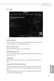
... . DHCP (Auto IP), Auto ASRock Internet Flash downloads and updates the latest UEFI firmware version from our servers for you Sanitize SSD, all user data will be permanently destroyed on the SSD and cannot be recovered. Please setup network configuration before using Internet Flash. *For BIOS backup and recovery purpose, it is recommended to plug in your USB storage device and run Instant Flash to update your UEFI. 4.7 Tools H510M-HDV R2.0 H510M-HVS R2.0 UEFI Tech Service Contact ASRock Tech Service if...
... . DHCP (Auto IP), Auto ASRock Internet Flash downloads and updates the latest UEFI firmware version from our servers for you Sanitize SSD, all user data will be permanently destroyed on the SSD and cannot be recovered. Please setup network configuration before using Internet Flash. *For BIOS backup and recovery purpose, it is recommended to plug in your USB storage device and run Instant Flash to update your UEFI. 4.7 Tools H510M-HDV R2.0 H510M-HVS R2.0 UEFI Tech Service Contact ASRock Tech Service if...

User Manual
Page 66
UEFI Download Server Select a server to configure internet connection settings for Internet Flash. Network Configuration Use this to download the UEFI firmware. 60 English Internet Setting Enable or disable sound effects in the setup utility.
UEFI Download Server Select a server to configure internet connection settings for Internet Flash. Network Configuration Use this to download the UEFI firmware. 60 English Internet Setting Enable or disable sound effects in the setup utility.

User Manual
Page 69
H510M-HDV R2.0 H510M-HVS R2.0 4.9 Security Screen In this section you may also clear the user password. You may set or change the settings in the UEFI Setup Utility. Disable this item to remove the password. Users are unable to remove the password. Intel(R) Platform Trust Technology Enable/disable Intel PTT in the UEFI Setup Utility. Leave it blank and press enter to change the settings in ME. Secure Boot Use this option to change the supervisor/user password for the user account. Leave it blank and...
H510M-HDV R2.0 H510M-HVS R2.0 4.9 Security Screen In this section you may also clear the user password. You may set or change the settings in the UEFI Setup Utility. Disable this item to remove the password. Users are unable to remove the password. Intel(R) Platform Trust Technology Enable/disable Intel PTT in the UEFI Setup Utility. Leave it blank and press enter to change the settings in ME. Secure Boot Use this option to change the supervisor/user password for the user account. Leave it blank and...


