
Intel Rapid Storage Guide
Page 12
... to RAID. 5. Select 1: Create RAID Volume and press Enter. 3. When finished press Enter. 12 Switch the SATA Operation Mode option to create a RAID volume. 1. Enable RAID in System BIOS Use the instructions included with your motherboard to enable RAID in the system BIOS, a RAID volume must be created, and the F6 installation method must be used to load the Intel® Rapid Storage Technology driver during POST, press Ctrl and i at the same time to enter the option ROM user...
... to RAID. 5. Select 1: Create RAID Volume and press Enter. 3. When finished press Enter. 12 Switch the SATA Operation Mode option to create a RAID volume. 1. Enable RAID in System BIOS Use the instructions included with your motherboard to enable RAID in the system BIOS, a RAID volume must be created, and the F6 installation method must be used to load the Intel® Rapid Storage Technology driver during POST, press Ctrl and i at the same time to enter the option ROM user...
Intel Rapid Storage Guide
Page 13
... a floppy disk with a screen asking you need to scroll through the list as all controllers may not be visible. 6. Press F6 when you see a prompt that says, Press F6 if you to create the volume. 9. Leave 13 When you have successfully installed the driver and Windows setup should continue. Select 4: Exit and press Enter. 11. Use the up and down arrow keys...
... a floppy disk with a screen asking you need to scroll through the list as all controllers may not be visible. 6. Press F6 when you see a prompt that says, Press F6 if you to create the volume. 9. Leave 13 When you have successfully installed the driver and Windows setup should continue. Select 4: Exit and press Enter. 11. Use the up and down arrow keys...

Intel Rapid Storage Guide
Page 16
... Windows setup (during operating system installation. Note If you do not need to Specify Additional Device. 3. You can use the Floppy Configuration Utility to install the Intel® Rapid Storage Technology driver using F6 when in AHCI/RAID mode In order to install an operating system onto a single Serial ATA hard drive when the system is in the status line that says, Please insert the disk labeled Manufacturer-supplied hardware support disk into Drive A:, insert a floppy disk...
... Windows setup (during operating system installation. Note If you do not need to Specify Additional Device. 3. You can use the Floppy Configuration Utility to install the Intel® Rapid Storage Technology driver using F6 when in AHCI/RAID mode In order to install an operating system onto a single Serial ATA hard drive when the system is in the status line that says, Please insert the disk labeled Manufacturer-supplied hardware support disk into Drive A:, insert a floppy disk...

RAID Installation Guide
Page 7
... UEFI SETUP UTILITY Tool and highlight "Easy RAID Installer". STEP 2: Use ASRock Easy RAID Installer Easy RAID Installer can copy the RAID driver from a support CD to your USB storage device with RAID functions, please follow the procedures below. Please note that this document for all models A. Press [Enter] to save the configuration changes and exit setup. STEP 4: Install Windows® 10 64-bit OS on your system, and press key to enter BIOS setup utility. Go to Advanced Storage Configuration and set RAID configuration. STEP 3: Set RAID configuration...
... UEFI SETUP UTILITY Tool and highlight "Easy RAID Installer". STEP 2: Use ASRock Easy RAID Installer Easy RAID Installer can copy the RAID driver from a support CD to your USB storage device with RAID functions, please follow the procedures below. Please note that this document for all models A. Press [Enter] to save the configuration changes and exit setup. STEP 4: Install Windows® 10 64-bit OS on your system, and press key to enter BIOS setup utility. Go to Advanced Storage Configuration and set RAID configuration. STEP 3: Set RAID configuration...

RAID Installation Guide
Page 23
... Intel® RAID drivers into a USB flash disk You can download the drivers from ASRock's website and unzip the files into a USB flash disk or copy the files from ASRock's motherboard support CD. (Please copy the files under the following directory: 32 bit: ..\i386\Win7_Intel.. 64-bit: ..\AMD64\Win7-64_Intel.. After the UEFI and RAID BIOS setup, please follow the steps below. Installing Windows® on a HDD larger than 2TB in RAID mode Windows® 10 does not support HDD's larger...
... Intel® RAID drivers into a USB flash disk You can download the drivers from ASRock's website and unzip the files into a USB flash disk or copy the files from ASRock's motherboard support CD. (Please copy the files under the following directory: 32 bit: ..\i386\Win7_Intel.. 64-bit: ..\AMD64\Win7-64_Intel.. After the UEFI and RAID BIOS setup, please follow the steps below. Installing Windows® on a HDD larger than 2TB in RAID mode Windows® 10 does not support HDD's larger...

User Manual
Page 4
Contents Chapter 1 Introduction 1 1.1 Package Contents 1 1.2 Specifications 2 1.3 Motherboard Layout 7 1.4 I/O Panel 9 Chapter 2 Installation 11 2.1 Installing the CPU 12 2.2 Installing the CPU Fan and Heatsink 15 2.3 Installing Memory Modules (DIMM) 16 2.4 Expansion Slots (PCI Express Slots) 18 2.5 Jumpers Setup 19 2.6 Onboard Headers and Connectors 20 2.7 Post Status Checker 26 2.8 CrossFireXTM and Quad CrossFireXTM Operation Guide 27 2.8.1 Installing Two CrossFireXTM-Ready Graphics Cards 27 2.8.2 Driver Installation and Setup 29 2.9 M.2 WiFi/BT Module and ...
Contents Chapter 1 Introduction 1 1.1 Package Contents 1 1.2 Specifications 2 1.3 Motherboard Layout 7 1.4 I/O Panel 9 Chapter 2 Installation 11 2.1 Installing the CPU 12 2.2 Installing the CPU Fan and Heatsink 15 2.3 Installing Memory Modules (DIMM) 16 2.4 Expansion Slots (PCI Express Slots) 18 2.5 Jumpers Setup 19 2.6 Onboard Headers and Connectors 20 2.7 Post Status Checker 26 2.8 CrossFireXTM and Quad CrossFireXTM Operation Guide 27 2.8.1 Installing Two CrossFireXTM-Ready Graphics Cards 27 2.8.2 Driver Installation and Setup 29 2.9 M.2 WiFi/BT Module and ...
User Manual
Page 7
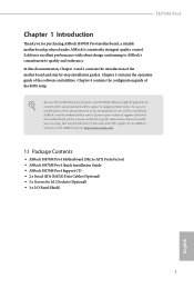
... specifications and the BIOS software might be updated, the content of the motherboard and step-by-step installation guides. If you for M.2 Sockets (Optional) • 1 x I/O Panel Shield 1 English Chapter 3 contains the operation guide of the BIOS setup. You may find the latest VGA cards and CPU support list on ASRock's website without notice. ASRock website http://www.asrock.com. 1.1 Package Contents • ASRock H470M Pro4 Motherboard (Micro ATX Form Factor) • ASRock H470M Pro4 Quick Installation Guide • ASRock H470M Pro4 Support CD • 2 x Serial ATA (SATA...
... specifications and the BIOS software might be updated, the content of the motherboard and step-by-step installation guides. If you for M.2 Sockets (Optional) • 1 x I/O Panel Shield 1 English Chapter 3 contains the operation guide of the BIOS setup. You may find the latest VGA cards and CPU support list on ASRock's website without notice. ASRock website http://www.asrock.com. 1.1 Package Contents • ASRock H470M Pro4 Motherboard (Micro ATX Form Factor) • ASRock H470M Pro4 Quick Installation Guide • ASRock H470M Pro4 Support CD • 2 x Serial ATA (SATA...
User Manual
Page 11
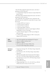
...Audio Connector • 1 x Thunderbolt AIC Connector (5-pin) (Supports ASRock Thunderbolt 3 AIC R2.0 Card only) • 1 x USB 2.0 Header (Supports 2 USB 2.0 ports) (Supports ESD Protection) • 2 x USB 3.2 Gen1 Headers (Support 4 USB 3.2 Gen1 ports) (Supports ESD Protection) BIOS Feature • AMI UEFI Legal BIOS with multilingual GUI support • ACPI 6.0 Compliant wake up events • SMBIOS 2.7 Support • CPU Core/Cache, GT, DRAM, VPPM, PCH, VCCSA,VCCSFR Voltage Multi-adjustment Hardware Monitor • Temperature Sensing: CPU, CPU/Water Pump, Chassis/Water Pump Fans...
...Audio Connector • 1 x Thunderbolt AIC Connector (5-pin) (Supports ASRock Thunderbolt 3 AIC R2.0 Card only) • 1 x USB 2.0 Header (Supports 2 USB 2.0 ports) (Supports ESD Protection) • 2 x USB 3.2 Gen1 Headers (Support 4 USB 3.2 Gen1 ports) (Supports ESD Protection) BIOS Feature • AMI UEFI Legal BIOS with multilingual GUI support • ACPI 6.0 Compliant wake up events • SMBIOS 2.7 Support • CPU Core/Cache, GT, DRAM, VPPM, PCH, VCCSA,VCCSFR Voltage Multi-adjustment Hardware Monitor • Temperature Sensing: CPU, CPU/Water Pump, Chassis/Water Pump Fans...

User Manual
Page 14
... Slots (DDR4_A1, DDR4_B1) 5 2 x 288-pin DDR4 DIMM Slots (DDR4_A2, DDR4_B2) 6 CPU/Water Pump Fan Connector (CPU_FAN2/WP) 7 RGB LED Header (RGB_LED2) 8 Addressable LED Header (ADDR_LED1) 9 ATX Power Connector (ATXPWR1) 10 USB 3.2 Gen1 Header (USB3_5_6) 11 SATA3 Connector (SATA3_0) 12 SATA3 Connector (SATA3_1) 13 Chassis/Water Pump Fan Connector (CHA_FAN2/WP) 14 USB 3.2 Gen1 Header (USB3_3_4) 15 SATA3 Connector (SATA3_2) 16 SATA3 Connector (SATA3_3) 17 System Panel Header (PANEL1) 18 Clear CMOS Jumper (CLRMOS1) 19 Chassis Intrusion and Speaker Header (SPK_CI1) 20 SATA3 Connector...
... Slots (DDR4_A1, DDR4_B1) 5 2 x 288-pin DDR4 DIMM Slots (DDR4_A2, DDR4_B2) 6 CPU/Water Pump Fan Connector (CPU_FAN2/WP) 7 RGB LED Header (RGB_LED2) 8 Addressable LED Header (ADDR_LED1) 9 ATX Power Connector (ATXPWR1) 10 USB 3.2 Gen1 Header (USB3_5_6) 11 SATA3 Connector (SATA3_0) 12 SATA3 Connector (SATA3_1) 13 Chassis/Water Pump Fan Connector (CHA_FAN2/WP) 14 USB 3.2 Gen1 Header (USB3_3_4) 15 SATA3 Connector (SATA3_2) 16 SATA3 Connector (SATA3_3) 17 System Panel Header (PANEL1) 18 Clear CMOS Jumper (CLRMOS1) 19 Chassis Intrusion and Speaker Header (SPK_CI1) 20 SATA3 Connector...

User Manual
Page 25
...) 2-pin Jumper Short: Clear CMOS Open: Default CLRMOS1 allows you to clear the data in CMOS includes system setup information such as system password, date, time, and system setup parameters. English 19 H470M Pro4 2.5 Jumpers Setup The illustration shows how jumpers are setup. To clear and reset the system parameters to default setup, please turn off the computer and unplug the power cord, then use a jumper cap to clear the CMOS when you just finish updating the BIOS, you...
...) 2-pin Jumper Short: Clear CMOS Open: Default CLRMOS1 allows you to clear the data in CMOS includes system setup information such as system password, date, time, and system setup parameters. English 19 H470M Pro4 2.5 Jumpers Setup The illustration shows how jumpers are setup. To clear and reset the system parameters to default setup, please turn off the computer and unplug the power cord, then use a jumper cap to clear the CMOS when you just finish updating the BIOS, you...

User Manual
Page 29
...-pin ATX power connector. Connecting an ATX 12V 4-pin cable here is for the CPU and not the graphics card. To use a 4-pin ATX power supply, please plug it along Pin 1 and Pin 13. 8 5 This motherboard provides a 8-pin ATX 12V 4 1 power connector. Do not plug the PCIe power cable to connect a 3-Pin CPU water cooler fan, please connect it along Pin 1 and Pin 5. *Warning: Please make sure that the power cable connected is optional. *The power supply plug fits into this connector. English 23 If you plan to this connector in only one orientation. H470M Pro4 CPU...
...-pin ATX power connector. Connecting an ATX 12V 4-pin cable here is for the CPU and not the graphics card. To use a 4-pin ATX power supply, please plug it along Pin 1 and Pin 13. 8 5 This motherboard provides a 8-pin ATX 12V 4 1 power connector. Do not plug the PCIe power cable to connect a 3-Pin CPU water cooler fan, please connect it along Pin 1 and Pin 5. *Warning: Please make sure that the power cable connected is optional. *The power supply plug fits into this connector. English 23 If you plan to this connector in only one orientation. H470M Pro4 CPU...

User Manual
Page 33
... cards will operate as 12-pipe cards while in CrossFireXTM mode. 5. H470M Pro4 2.8 CrossFireXTM and Quad CrossFireXTM Operation Guide This motherboard supports CrossFireXTM and Quad CrossFireXTM that are properly seated on the top of the graphics cards. (The CrossFire Bridge is recommended to use identical CrossFireXTM-ready graphics cards that allows you to install up to three identical PCI Express x16 graphics cards. 1. CrossFire Bridge Step 2 Connect two graphics cards by installing...
... cards will operate as 12-pipe cards while in CrossFireXTM mode. 5. H470M Pro4 2.8 CrossFireXTM and Quad CrossFireXTM Operation Guide This motherboard supports CrossFireXTM and Quad CrossFireXTM that are properly seated on the top of the graphics cards. (The CrossFire Bridge is recommended to use identical CrossFireXTM-ready graphics cards that allows you to install up to three identical PCI Express x16 graphics cards. 1. CrossFire Bridge Step 2 Connect two graphics cards by installing...
User Manual
Page 35
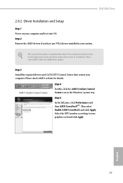
... your graphics card and click Apply. Select the GPU number according to installation. H470M Pro4 2.8.2 Driver Installation and Setup Step 1 Power on your computer. Step 5 In the left pane, click Performance and then AMD CrossFireXTM. Step 3 Install the required drivers and CATALYST Control Center then restart your computer and boot into OS. Please check AMD's website for AMD driver updates. The Catalyst Uninstaller is an optional download. Then select Enable AMD CrossFireX...
... your graphics card and click Apply. Select the GPU number according to installation. H470M Pro4 2.8.2 Driver Installation and Setup Step 1 Power on your computer. Step 5 In the left pane, click Performance and then AMD CrossFireXTM. Step 3 Install the required drivers and CATALYST Control Center then restart your computer and boot into OS. Please check AMD's website for AMD driver updates. The Catalyst Uninstaller is an optional download. Then select Enable AMD CrossFireX...
User Manual
Page 44
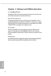
... installation wizard to install it. 38 English Drivers Menu The drivers compatible to your system will be auto-detected and listed on a specific item then follow the order from top to bottom to display the menu. Click on the support CD driver page. If the Main Menu does not appear automatically, locate and double click on the file "ASRSETUP.EXE" in your CD-ROM drive. Utilities Menu The Utilities Menu shows the application software...
... installation wizard to install it. 38 English Drivers Menu The drivers compatible to your system will be auto-detected and listed on a specific item then follow the order from top to bottom to display the menu. Click on the support CD driver page. If the Main Menu does not appear automatically, locate and double click on the file "ASRSETUP.EXE" in your CD-ROM drive. Utilities Menu The Utilities Menu shows the application software...

User Manual
Page 76
... link speed for Directed I/O helps your virtual machine monitor better utilize hardware by improving application compatibility and reliability, and providing additional levels of manageability, security, isolation, and I/O performance. SR-IOV Support If system has SR-IOV capable PCIe Devices, this option Enables or Disables Single Root IO Virtualization Support. VT-d Intel® Virtualization Technology for PCIE1. 70 English 4.6.2 Chipset Configuration Primary Graphics Adapter Select a primary VGA. Auto mode is optimizing for overclocking.
... link speed for Directed I/O helps your virtual machine monitor better utilize hardware by improving application compatibility and reliability, and providing additional levels of manageability, security, isolation, and I/O performance. SR-IOV Support If system has SR-IOV capable PCIe Devices, this option Enables or Disables Single Root IO Virtualization Support. VT-d Intel® Virtualization Technology for PCIE1. 70 English 4.6.2 Chipset Configuration Primary Graphics Adapter Select a primary VGA. Auto mode is optimizing for overclocking.

User Manual
Page 77
.... H470M Pro4 PCIE2 Link Speed Select the link speed for enhanced PCI Express power saving in OS. PCH DMI ASPM Support This option enables/disables the ASPM support for all CPU downstream devices. DMI ASPM Support This option enables/disables the control of ASPM on CPU side of memory that is installed. Select enable to keep the integrated graphics enabled at all PCH DMI devices. Inte(R) Ethernet Connection I219-V Enable or disable the onboard network interface controller (Intel® I219V). IGPU Multi-Monitor...
.... H470M Pro4 PCIE2 Link Speed Select the link speed for enhanced PCI Express power saving in OS. PCH DMI ASPM Support This option enables/disables the ASPM support for all CPU downstream devices. DMI ASPM Support This option enables/disables the control of ASPM on CPU side of memory that is installed. Select enable to keep the integrated graphics enabled at all PCH DMI devices. Inte(R) Ethernet Connection I219-V Enable or disable the onboard network interface controller (Intel® I219V). IGPU Multi-Monitor...

User Manual
Page 80
4.6.4 Intel® Thunderbolt Discrete Thunderbolt(TM) Support Enable or disable the Discrete Thunderbolt(TM) Support. Security Level This item allows you to choose a security level for OSUP. Titan Ridge Workaround for OSUP Enable or disable Titan Ridge Workaround for the Thunderbolt ports. 74 English Thunderbolt Usb Support Enabled to allow booting from Bootable devices which are present behind Thunderbolt. Thunderbolt Boot Support Enabled to allow booting from Usb devices which are present behind Thunderbolt.
4.6.4 Intel® Thunderbolt Discrete Thunderbolt(TM) Support Enable or disable the Discrete Thunderbolt(TM) Support. Security Level This item allows you to choose a security level for OSUP. Titan Ridge Workaround for OSUP Enable or disable Titan Ridge Workaround for the Thunderbolt ports. 74 English Thunderbolt Usb Support Enabled to allow booting from Bootable devices which are present behind Thunderbolt. Thunderbolt Boot Support Enabled to allow booting from Usb devices which are present behind Thunderbolt.
User Manual
Page 85
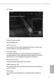
... Sanitization Tool After you can start installing the operating system in your USB storage device and run Instant Flash to RAID, then you Sanitize SSD, all user data will be permanently destroyed on the SSD and cannot be recovered. Please setup network configuration before using UEFI Tech Service. SSD Secure Erase Tool All the SSD's listed that supports Secure Erase function. 4.7 Tools H470M Pro4 ASRock Polychrome RGB Select LED lighting color.
... Sanitization Tool After you can start installing the operating system in your USB storage device and run Instant Flash to RAID, then you Sanitize SSD, all user data will be permanently destroyed on the SSD and cannot be recovered. Please setup network configuration before using UEFI Tech Service. SSD Secure Erase Tool All the SSD's listed that supports Secure Erase function. 4.7 Tools H470M Pro4 ASRock Polychrome RGB Select LED lighting color.
User Manual
Page 86
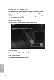
Please setup network configuration before using Internet Flash. *For BIOS backup and recovery purpose, it is recommended to download the UEFI firmware. 80 English Internet Setting Enable or disable sound effects in your USB pen drive before using this to configure internet connection settings for you. UEFI Download Server Select a server to plug in the setup utility. DHCP (Auto IP), Auto ASRock Internet Flash downloads and updates the latest UEFI firmware version from our servers for Internet Flash. Network Configuration Use this function. Internet Flash -
Please setup network configuration before using Internet Flash. *For BIOS backup and recovery purpose, it is recommended to download the UEFI firmware. 80 English Internet Setting Enable or disable sound effects in your USB pen drive before using this to configure internet connection settings for you. UEFI Download Server Select a server to plug in the setup utility. DHCP (Auto IP), Auto ASRock Internet Flash downloads and updates the latest UEFI firmware version from our servers for Internet Flash. Network Configuration Use this function. Internet Flash -

User Manual
Page 91
... Technology Enable/disable Intel PTT in the UEFI Setup Utility. H470M Pro4 4.9 Security Screen In this section you may also clear the user password. Supervisor Password Set or change the password for Secure Boot. Leave it blank and press enter to remove the password. Users are unable to use discrete TPM Module. 85 English You may set or change the supervisor/user password for the administrator account. User Password Set or change the password for the system. Secure Boot Use this option to change the settings...
... Technology Enable/disable Intel PTT in the UEFI Setup Utility. H470M Pro4 4.9 Security Screen In this section you may also clear the user password. Supervisor Password Set or change the password for Secure Boot. Leave it blank and press enter to remove the password. Users are unable to use discrete TPM Module. 85 English You may set or change the supervisor/user password for the administrator account. User Password Set or change the password for the system. Secure Boot Use this option to change the settings...


