

User Manual
Page 3
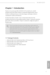
...1.1 Package Contents 1 1.2 Speciications 2 1.3 Motherboard Layout 5 1.4 I/O Panel 7 Chapter 2 Installation 9 2.1 Installing the CPU 10 2.2 Installing the CPU Fan and Heatsink 13 2.3 Installing Memory Modules (DIMM) 14 2.4 Expansion Slots (PCI Express Slots) 16 2.5 Jumpers Setup 17 2.6 Onboard Headers and Connectors 18 Chapter 3 Software and Utilities Operation 22 3.1 Installing Drivers 22 3.2 ASRock Live Update & APP Shop 23 3.2.1 UI Overview 23 3.2.2 Apps 24 3.2.3 BIOS & Drivers 27 3.2.4 Setting 28 3.3 Enabling USB Ports for Windows® 7 Installation 29
...1.1 Package Contents 1 1.2 Speciications 2 1.3 Motherboard Layout 5 1.4 I/O Panel 7 Chapter 2 Installation 9 2.1 Installing the CPU 10 2.2 Installing the CPU Fan and Heatsink 13 2.3 Installing Memory Modules (DIMM) 14 2.4 Expansion Slots (PCI Express Slots) 16 2.5 Jumpers Setup 17 2.6 Onboard Headers and Connectors 18 Chapter 3 Software and Utilities Operation 22 3.1 Installing Drivers 22 3.2 ASRock Live Update & APP Shop 23 3.2.1 UI Overview 23 3.2.2 Apps 24 3.2.3 BIOS & Drivers 27 3.2.4 Setting 28 3.3 Enabling USB Ports for Windows® 7 Installation 29
User Manual
Page 5
... robust design conforming to ASRock's commitment to change without further notice. You may ind the latest VGA cards and CPU support list on ASRock's website without notice. ASRock website http://www.asrock.com. 1.1 Package Contents • ASRock H110M-GL/D3 Motherboard (Micro ATX Form Factor) • ASRock H110M-GL/D3 Quick Installation Guide • ASRock H110M-GL/D3 Support CD • 2 x Serial ATA (SATA) Data Cables (Optional) • 1 x I/O Panel Shield 1 English If you are using. In this documentation will be updated, the content of...
... robust design conforming to ASRock's commitment to change without further notice. You may ind the latest VGA cards and CPU support list on ASRock's website without notice. ASRock website http://www.asrock.com. 1.1 Package Contents • ASRock H110M-GL/D3 Motherboard (Micro ATX Form Factor) • ASRock H110M-GL/D3 Quick Installation Guide • ASRock H110M-GL/D3 Support CD • 2 x Serial ATA (SATA) Data Cables (Optional) • 1 x I/O Panel Shield 1 English If you are using. In this documentation will be updated, the content of...

User Manual
Page 7
...; 1 x USB 3.0 Header (Supports 2 USB 3.0 ports) (Supports ESD Protection (ASRock Full Spike Protection)) *USB3_2_3 is shared with LED (ACT/LINK LED and SPEED LED) • HD Audio Jacks: Line in / Front Speaker / Microphone Storage 4 x SATA3 6.0 Gb/s Connectors, support NCQ, AHCI and Hot Plug Connector • 1 x COM Port Header • 1 x TPM Header • 1 x Chassis Intrusion and Speaker Header • 1 x CPU Fan Connector (4-pin) (Smart Fan Speed Control) • 2 x Chassis Fan Connector (4-pin) (Smart Fan Speed Con- H110M-GL/D3 LAN Rear Panel I/O • PCIE x1 Gigabit LAN 10...
...; 1 x USB 3.0 Header (Supports 2 USB 3.0 ports) (Supports ESD Protection (ASRock Full Spike Protection)) *USB3_2_3 is shared with LED (ACT/LINK LED and SPEED LED) • HD Audio Jacks: Line in / Front Speaker / Microphone Storage 4 x SATA3 6.0 Gb/s Connectors, support NCQ, AHCI and Hot Plug Connector • 1 x COM Port Header • 1 x TPM Header • 1 x Chassis Intrusion and Speaker Header • 1 x CPU Fan Connector (4-pin) (Smart Fan Speed Control) • 2 x Chassis Fan Connector (4-pin) (Smart Fan Speed Con- H110M-GL/D3 LAN Rear Panel I/O • PCIE x1 Gigabit LAN 10...

User Manual
Page 8
... 29 for more detailed instructions. * For the updated Windows® 10 driver, please visit ASRock's website for possible damage caused by CPU temperature) • CPU/Chassis Fan multi-speed control • CASE OPEN detection • Voltage monitoring: +12V, +5V, +3.3V, CPU Vcore OS • Microsot® Windows® 10 64-bit / 8.1 64-bit / 7 32-bit / 7 64- adjustment Hardware Monitor • CPU/Chassis temperature sensing • CPU/Chassis Fan Tachometer • CPU/Chassis Quiet Fan (Auto adjust chassis fan speed by overclocking. It should be done...
... 29 for more detailed instructions. * For the updated Windows® 10 driver, please visit ASRock's website for possible damage caused by CPU temperature) • CPU/Chassis Fan multi-speed control • CASE OPEN detection • Voltage monitoring: +12V, +5V, +3.3V, CPU Vcore OS • Microsot® Windows® 10 64-bit / 8.1 64-bit / 7 32-bit / 7 64- adjustment Hardware Monitor • CPU/Chassis temperature sensing • CPU/Chassis Fan Tachometer • CPU/Chassis Quiet Fan (Auto adjust chassis fan speed by overclocking. It should be done...

User Manual
Page 20
... PCIE2 (PCIe 2.0 x1 slot) is used for PCI Express x16 lane width graphics cards. Please read the documentation of the expansion card and make sure that the power supply is switched of or the power cord is used for PCI Express x1 lane width cards PCIE3 (PCIe 2.0 x1 slot) is unplugged. Before installing an expansion card, please make necessary hardware settings for the card before you start the installation. 2.4 Expansion Slots (PCI Express Slots) here are 3 PCI Express slots on the motherboard.
... PCIE2 (PCIe 2.0 x1 slot) is used for PCI Express x16 lane width graphics cards. Please read the documentation of the expansion card and make sure that the power supply is switched of or the power cord is used for PCI Express x1 lane width cards PCIE3 (PCIe 2.0 x1 slot) is unplugged. Before installing an expansion card, please make necessary hardware settings for the card before you start the installation. 2.4 Expansion Slots (PCI Express Slots) here are 3 PCI Express slots on the motherboard.

User Manual
Page 21
... the CMOS battery is placed on CLRMOS1 for 15 seconds, use a jumper cap to clear the data in CMOS. he illustration shows how jumpers are "Short" when a jumper cap is placed on the pins, the jumper is placed on these 2 pins. Please be noted that the password, date, time, and user default proile will be detected. If you update the BIOS. Please adjust the BIOS option "Clear Status" to clear the...
... the CMOS battery is placed on CLRMOS1 for 15 seconds, use a jumper cap to clear the data in CMOS. he illustration shows how jumpers are "Short" when a jumper cap is placed on the pins, the jumper is placed on these 2 pins. Please be noted that the password, date, time, and user default proile will be detected. If you update the BIOS. Please adjust the BIOS option "Clear Status" to clear the...
User Manual
Page 23
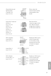
.... Dummy 1 English 19 H110M-GL/D3 Chassis Intrusion and Speaker Header (7-pin SPK_CI1) (see p.5, No. 5) USB_PWR -B +B GND DUMMY 1 GND +A -A USB_PWR Besides four USB 2.0 ports on the I /O panel, there IntA_PB_SSRX+ GND is one header on this motherboard. Serial ATA3 Connectors (SATA3_0) (see p.5, No. 10) (SATA3_1) (see p.5, No. 9) (SATA3_2) (see p.5, No. 7) (SATA3_3) (see p.5, No. 8) SATA3_0 SATA3_2 SATA3_1 SATA3_3 hese four SATA3 connectors support SATA data cables for internal storage devices with up to...
.... Dummy 1 English 19 H110M-GL/D3 Chassis Intrusion and Speaker Header (7-pin SPK_CI1) (see p.5, No. 5) USB_PWR -B +B GND DUMMY 1 GND +A -A USB_PWR Besides four USB 2.0 ports on the I /O panel, there IntA_PB_SSRX+ GND is one header on this motherboard. Serial ATA3 Connectors (SATA3_0) (see p.5, No. 10) (SATA3_1) (see p.5, No. 9) (SATA3_2) (see p.5, No. 7) (SATA3_3) (see p.5, No. 8) SATA3_0 SATA3_2 SATA3_1 SATA3_3 hese four SATA3 connectors support SATA data cables for internal storage devices with up to...

User Manual
Page 24
... the AC'97 audio panel. Chassis Fan Connector (4-pin CHA_FAN1) (see p.5, No. 18) (4-pin CHA_FAN2) (see p.5, No. 2) his header is for J_SENSE connecting audio devices OUT2_R MIC2_R to the ground pin. GND FAN_VOLTAGE CHA_FAN_SPEED FAN_SPEED_CONTROL CPU Fan Connector (4-pin CPU_FAN1) (see p.5, No. 11) Please connect fan cables FAN_SPEED_CONTROL CHA_FAN_SPEED FAN_VOLTAGE GND to the fan connector and match the black wire to the front audio panel. Please follow the instructions in the Realtek Control panel and adjust "Recording...
... the AC'97 audio panel. Chassis Fan Connector (4-pin CHA_FAN1) (see p.5, No. 18) (4-pin CHA_FAN2) (see p.5, No. 2) his header is for J_SENSE connecting audio devices OUT2_R MIC2_R to the ground pin. GND FAN_VOLTAGE CHA_FAN_SPEED FAN_SPEED_CONTROL CPU Fan Connector (4-pin CPU_FAN1) (see p.5, No. 11) Please connect fan cables FAN_SPEED_CONTROL CHA_FAN_SPEED FAN_VOLTAGE GND to the fan connector and match the black wire to the front audio panel. Please follow the instructions in the Realtek Control panel and adjust "Recording...

User Manual
Page 25
... TTXD1 DDCD#1 his connector supports Trusted Platform Module (TPM) system, which can securely store keys, digital certiicates, passwords, and data. H110M-GL/D3 ATX Power Connector (24-pin ATXPWR1) (see p.5, No. 4) ATX 12V Power Connector (4-pin ATX12V1) (see p.5, No. 1) Serial Port Header (9-pin COM2) (see p.5, No. 15) 1 GND SMB_CLK_MAIN SMB_DATA_MAIN LAD2 LAD1 GND S_PWRDWN# SERIRQ# GND his COM2 header supports a serial port module. To use a 20-pin ATX power supply, please plug it along Pin 1 and Pin 13. his motherboard provides a 24-pin ATX power connector.
... TTXD1 DDCD#1 his connector supports Trusted Platform Module (TPM) system, which can securely store keys, digital certiicates, passwords, and data. H110M-GL/D3 ATX Power Connector (24-pin ATXPWR1) (see p.5, No. 4) ATX 12V Power Connector (4-pin ATX12V1) (see p.5, No. 1) Serial Port Header (9-pin COM2) (see p.5, No. 15) 1 GND SMB_CLK_MAIN SMB_DATA_MAIN LAD2 LAD1 GND S_PWRDWN# SERIRQ# GND his COM2 header supports a serial port module. To use a 20-pin ATX power supply, please plug it along Pin 1 and Pin 13. his motherboard provides a 24-pin ATX power connector.
User Manual
Page 26
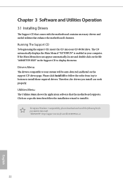
... Main Menu does not appear automatically, locate and double click on the support CD driver page. Drivers Menu he drivers compatible to your system will be auto-detected and listed on the ile "ASRSETUP.EXE" in your CD-ROM drive. Please click Install All or follow the installation wizard to install those required drivers. To improve Windows 7 compatibility, please download and install the following hot ix provided by Microsot. Chapter 3 Software and Utilities...
... Main Menu does not appear automatically, locate and double click on the support CD driver page. Drivers Menu he drivers compatible to your system will be auto-detected and listed on the ile "ASRSETUP.EXE" in your CD-ROM drive. Please click Install All or follow the installation wizard to install those required drivers. To improve Windows 7 compatibility, please download and install the following hot ix provided by Microsot. Chapter 3 Software and Utilities...
User Manual
Page 27
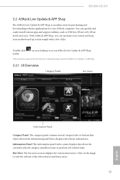
.... H110M-GL/D3 3.2 ASRock Live Update & APP Shop he ASRock Live Update & APP Shop is an online store for purchasing and downloading sotware applications for your motherboard up to visit the website of the selected news and know more . Information Panel: he information panel in the center displays data about the currently selected category and allows users to download apps from the ASRock Live Update & APP...
.... H110M-GL/D3 3.2 ASRock Live Update & APP Shop he ASRock Live Update & APP Shop is an online store for purchasing and downloading sotware applications for your motherboard up to visit the website of the selected news and know more . Information Panel: he information panel in the center displays data about the currently selected category and allows users to download apps from the ASRock Live Update & APP...

User Manual
Page 33
... ahead to install Windows® 7 OS. 29 English H110M-GL/D3 3.3 Enabling USB Ports for Windows® 7 Installation Intel® Braswell and Skylake has removed their motherboard won't work. USB3.0). Due to that fact that XHCI is an optical disc drive, PS/2 ports and PS/2 Keyboard or mouse on their support for the USB ports to create a new ISO ile with the Intel® USB 3.0 eXtensible Host Controller (xHCI) drivers packed into...
... ahead to install Windows® 7 OS. 29 English H110M-GL/D3 3.3 Enabling USB Ports for Windows® 7 Installation Intel® Braswell and Skylake has removed their motherboard won't work. USB3.0). Due to that fact that XHCI is an optical disc drive, PS/2 ports and PS/2 Keyboard or mouse on their support for the USB ports to create a new ISO ile with the Intel® USB 3.0 eXtensible Host Controller (xHCI) drivers packed into...
User Manual
Page 34
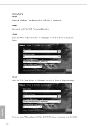
Step 4 Select the "USB Driver Folder" by clicking the red circle as shown as the picture below . Instructions Step 1 Insert the Windows® 7 installation disk or USB drive to your CD-ROM. 30 English Step 3 Select the "Win7 Folder" from Step1 by clicking the red circle as shown as the picture below . If you are using ASRock's Support CD for the USB 3.0 driver, please select your system. Step 2 Extract the tool (Win7 USB Patcher) and launch it.
Step 4 Select the "USB Driver Folder" by clicking the red circle as shown as the picture below . Instructions Step 1 Insert the Windows® 7 installation disk or USB drive to your CD-ROM. 30 English Step 3 Select the "Win7 Folder" from Step1 by clicking the red circle as shown as the picture below . If you are using ASRock's Support CD for the USB 3.0 driver, please select your system. Step 2 Extract the tool (Win7 USB Patcher) and launch it.

User Manual
Page 36
... your screen. 4.1.1 UEFI Menu Bar he top of and then back on. Chapter 4 UEFI SETUP UTILITY 4.1 Introduction his section explains how to use the UEFI SETUP UTILITY to enter the UEFI SETUP UTILITY ater POST, restart the system by pressing + + , or by pressing the reset button on the system chassis. You may also restart by turning the system of the screen has a menu bar with its test routines. If you power on...
... your screen. 4.1.1 UEFI Menu Bar he top of and then back on. Chapter 4 UEFI SETUP UTILITY 4.1 Introduction his section explains how to use the UEFI SETUP UTILITY to enter the UEFI SETUP UTILITY ater POST, restart the system by pressing + + , or by pressing the reset button on the system chassis. You may also restart by turning the system of the screen has a menu bar with its test routines. If you power on...
User Manual
Page 37
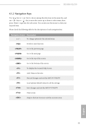
... screen To display the General Help Screen Add / Remove Favorite Discard changes and exit the SETUP UTILITY Load optimal default values for the descriptions of each navigation key. Please check the following table for all the settings Save changes and exit the SETUP UTILITY Print screen Jump to the Exit Screen or exit the current screen English 33 H110M-GL/D3 4.1.2 Navigation Keys Use < > key or < > key to choose among the selections on the menu...
... screen To display the General Help Screen Add / Remove Favorite Discard changes and exit the SETUP UTILITY Load optimal default values for the descriptions of each navigation key. Please check the following table for all the settings Save changes and exit the SETUP UTILITY Print screen Jump to the Exit Screen or exit the current screen English 33 H110M-GL/D3 4.1.2 Navigation Keys Use < > key or < > key to choose among the selections on the menu...
User Manual
Page 39
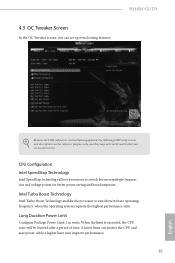
... your screen. Long Duration Power Limit Conigure Package Power Limit 1 in watts. A lower limit can set up overclocking features. H110M-GL/D3 Because the UEFI sotware is exceeded, the CPU ratio will be lowered ater a period of time. When the limit is constantly being updated, the following UEFI setup screens and descriptions are for better power saving and heat dissipation. CPU Coniguration Intel SpeedStep Technology Intel SpeedStep technology allows processors...
... your screen. Long Duration Power Limit Conigure Package Power Limit 1 in watts. A lower limit can set up overclocking features. H110M-GL/D3 Because the UEFI sotware is exceeded, the CPU ratio will be lowered ater a period of time. When the limit is constantly being updated, the following UEFI setup screens and descriptions are for better power saving and heat dissipation. CPU Coniguration Intel SpeedStep Technology Intel SpeedStep technology allows processors...

User Manual
Page 51
... graphics card is selected, the system will also automatically switch of when the power recovers. If [Power On] is installed. Onboard LAN Enable or disable the onboard network interface controller. Deep Sleep Conigure deep sleep mode for power saving when the computer is shut down the render unit when the GPU is allocated to boot up . H110M-GL/D3 PCH DMI ASPM Support his option enables/disables the ASPM support for lower power consumption. Onboard HD Audio Enable/disable onboard HD audio. If [Power...
... graphics card is selected, the system will also automatically switch of when the power recovers. If [Power On] is installed. Onboard LAN Enable or disable the onboard network interface controller. Deep Sleep Conigure deep sleep mode for power saving when the computer is shut down the render unit when the GPU is allocated to boot up . H110M-GL/D3 PCH DMI ASPM Support his option enables/disables the ASPM support for lower power consumption. Onboard HD Audio Enable/disable onboard HD audio. If [Power...
User Manual
Page 59
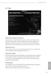
4.5 Tools H110M-GL/D3 OMG (Online Management Guard) Administrators are having trouble with your system via OMG. You may schedule the starting and ending hours of internet access granted to other required drivers automatically. Please setup network coniguration before using UEFI Tech Service. UEFI Tech Service Contact ASRock Tech Service if you are able to your PC. Easy Driver Installer For users that don't have an optical disk drive to install the drivers from...
4.5 Tools H110M-GL/D3 OMG (Online Management Guard) Administrators are having trouble with your system via OMG. You may schedule the starting and ending hours of internet access granted to other required drivers automatically. Please setup network coniguration before using UEFI Tech Service. UEFI Tech Service Contact ASRock Tech Service if you are able to your PC. Easy Driver Installer For users that don't have an optical disk drive to install the drivers from...

User Manual
Page 61
... recovery purpose, it is recommended to update your USB storage device and run Instant Flash to plug in the setup utility. DHCP (Auto IP), Auto ASRock Internet Flash downloads and updates the latest UEFI irmware version from our servers for Internet Flash. Internet Flash - Network Coniguration Use this function. UEFI Download Server Select a server to conigure internet connection settings for you. Max: 255 Min: 1 Instant Flash Save UEFI iles in your UEFI. H110M-GL/D3 value, the faster the fan speed. Please setup network coniguration before using...
... recovery purpose, it is recommended to update your USB storage device and run Instant Flash to plug in the setup utility. DHCP (Auto IP), Auto ASRock Internet Flash downloads and updates the latest UEFI irmware version from our servers for Internet Flash. Internet Flash - Network Coniguration Use this function. UEFI Download Server Select a server to conigure internet connection settings for you. Max: 255 Min: 1 Instant Flash Save UEFI iles in your UEFI. H110M-GL/D3 value, the faster the fan speed. Please setup network coniguration before using...

User Manual
Page 64
... option to enable or disable support for the administrator account. Only the administrator has authority to remove the password. User Password Set or change the password for the system. Disable this item to use discrete TPM Module. 60 English 4.7 Security Screen In this section you may also clear the user password. Intel(R) Platform Trust Technology Enable/disable Intel PTT in the UEFI Setup Utility. Leave it blank and press enter to change the settings in the UEFI Setup Utility...
... option to enable or disable support for the administrator account. Only the administrator has authority to remove the password. User Password Set or change the password for the system. Disable this item to use discrete TPM Module. 60 English 4.7 Security Screen In this section you may also clear the user password. Intel(R) Platform Trust Technology Enable/disable Intel PTT in the UEFI Setup Utility. Leave it blank and press enter to change the settings in the UEFI Setup Utility...


