User Manual
Page 3
...(SATA) / Serial ATAII (SATAII) Hard Disks Installation 25 2.11 Driver Installation Guide 25 2.12 Untied Overclocking Technology 25 3 BIOS SETUP UTILITY 26 3.1 Introduction 26 3.1.1 BIOS Menu Bar 26 3.1.2 Navigation Keys 27 3.2 Main Screen 27 3.3 OC Tweaker Screen 28 3.4 Advanced Screen 32 3.4.1 CPU Configuration 33 3.4.2 Chipset Configuration 36 3.4.3 ACPI Configuration 41 3.4.4 Storage Configuration 42 3.4.5 PCIPnP Configuration 44 3.4.6 Floppy Configuration 45 3.4.7 Super IO Configuration 45 3.4.8 USB Configuration 47 3.5 Hardware Health Event Monitoring Screen 48 3.6 Boot...
...(SATA) / Serial ATAII (SATAII) Hard Disks Installation 25 2.11 Driver Installation Guide 25 2.12 Untied Overclocking Technology 25 3 BIOS SETUP UTILITY 26 3.1 Introduction 26 3.1.1 BIOS Menu Bar 26 3.1.2 Navigation Keys 27 3.2 Main Screen 27 3.3 OC Tweaker Screen 28 3.4 Advanced Screen 32 3.4.1 CPU Configuration 33 3.4.2 Chipset Configuration 36 3.4.3 ACPI Configuration 41 3.4.4 Storage Configuration 42 3.4.5 PCIPnP Configuration 44 3.4.6 Floppy Configuration 45 3.4.7 Super IO Configuration 45 3.4.8 USB Configuration 47 3.5 Hardware Health Event Monitoring Screen 48 3.6 Boot...
User Manual
Page 9
... update your overclocking record under Windows® environment. Please be noted that the OC profile can easily enjoy the marvelous charging experience than before. It helps you can only be noticed that the USB flash drive or hard drive must use FAT32/16/12 file system. 11. With APP Charger driver installed, you to record the OC settings and share with your PC enters...
... update your overclocking record under Windows® environment. Please be noted that the OC profile can easily enjoy the marvelous charging experience than before. It helps you can only be noticed that the USB flash drive or hard drive must use FAT32/16/12 file system. 11. With APP Charger driver installed, you to record the OC settings and share with your PC enters...

User Manual
Page 11
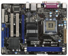
... SATA2 Connector (SATAII_1; Blue) 19 Floppy Connector (FLOPPY1) 6 North Bridge Controller 20 Clear CMOS Jumper (CLRCMOS1) 7 South Bridge Controller 21 PCI Express x1 Slot (PCIE2) 8 BIOS SPI Chip 22 Front Panel Audio Header 9 Chassis Speaker Header (HD_AUDIO1, White) (SPEAKER 1, White) 23 PCI Slots (PCI1- 2) 10 System Panel Header (PANEL1, White) 24 PCI Express x16 Slot (PCIE1) 11 Secondary SATA2 Connector (SATAII_2; Blue) 4 ATX Power Connector (ATXPWR1) 17 USB 2.0 Header (USB4_5, Blue) 5 2 x 240-pin DDR3 DIMM Slots 18 USB 2.0 Header (USB6_7, Blue) (Dual Channel: DDR3_A1...
... SATA2 Connector (SATAII_1; Blue) 19 Floppy Connector (FLOPPY1) 6 North Bridge Controller 20 Clear CMOS Jumper (CLRCMOS1) 7 South Bridge Controller 21 PCI Express x1 Slot (PCIE2) 8 BIOS SPI Chip 22 Front Panel Audio Header 9 Chassis Speaker Header (HD_AUDIO1, White) (SPEAKER 1, White) 23 PCI Slots (PCI1- 2) 10 System Panel Header (PANEL1, White) 24 PCI Express x16 Slot (PCIE1) 11 Secondary SATA2 Connector (SATAII_2; Blue) 4 ATX Power Connector (ATXPWR1) 17 USB 2.0 Header (USB4_5, Blue) 5 2 x 240-pin DDR3 DIMM Slots 18 USB 2.0 Header (USB6_7, Blue) (Dual Channel: DDR3_A1...

User Manual
Page 24
... updates. 24 Western Digital 7531 8642 If pin 5 and pin 6 are just for details: http://www.hitachigst.com/hdd/support/download.htm The above examples are shorted, SATA 1.5Gb/s will be enabled. In order to enable SATAII function, please follow the below SATAII hard disk setup guide. 2 . 9 SATAII Hard Disk Setup Guide Before installing SATAII hard disk to your reference. Some default setting of different vendors, the jumper pin setting methods may not be at SATAII mode...
... updates. 24 Western Digital 7531 8642 If pin 5 and pin 6 are just for details: http://www.hitachigst.com/hdd/support/download.htm The above examples are shorted, SATA 1.5Gb/s will be enabled. In order to enable SATAII function, please follow the below SATAII hard disk setup guide. 2 . 9 SATAII Hard Disk Setup Guide Before installing SATAII hard disk to your reference. Some default setting of different vendors, the jumper pin setting methods may not be at SATAII mode...

User Manual
Page 25
... before you enable Untied Overclocking function, please enter "Overclock Mode" option of the SATA data cable to the SATA / SATAII hard disk. 2.11 Driver Installation Guide To install the drivers to your optical drive first. Please follow the order from [Auto] to install those required drivers. Please refer to your chassis. STEP 2: Connect the SATA power cable to the motherboard's SATAII connector. Before you apply Untied Overclocking Technology. 25 You may install SATA / SATAII hard disks on page 10 for internal storage devices. STEP 3: Connect one end...
... before you enable Untied Overclocking function, please enter "Overclock Mode" option of the SATA data cable to the SATA / SATAII hard disk. 2.11 Driver Installation Guide To install the drivers to your optical drive first. Please follow the order from [Auto] to install those required drivers. Please refer to your chassis. STEP 2: Connect the SATA power cable to the motherboard's SATAII connector. Before you apply Untied Overclocking Technology. 25 You may install SATA / SATAII hard disks on page 10 for internal storage devices. STEP 3: Connect one end...

User Manual
Page 30
.... CPU Frequency (MHz) Use this option to adjust PCIE frequency. 30 Processor can switch between multiple frequency and voltage points to select Overclock Mode. If you install Windows® XP and select [Auto], you select [Manual], Untied Overclocking function is [Auto]. Please set the "Power Schemes" as "Portable/Laptop" to [Disable] if above issue occurs. Overclock Mode Use this to enable power savings. If you need to set this item to enable this function. If the CPU you adopt supports...
.... CPU Frequency (MHz) Use this option to adjust PCIE frequency. 30 Processor can switch between multiple frequency and voltage points to select Overclock Mode. If you install Windows® XP and select [Auto], you select [Manual], Untied Overclocking function is [Auto]. Please set the "Power Schemes" as "Portable/Laptop" to [Disable] if above issue occurs. Overclock Mode Use this to enable power savings. If you need to set this item to enable this function. If the CPU you adopt supports...
User Manual
Page 32
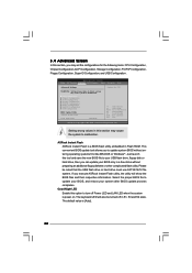
... following items: CPU Configuration, Chipset Configuration, ACPI Configuration, Storage Configuration, PCIPnP Configuration, Floppy Configuration, SuperIO Configuration, and USB Configuration. ASRock Instant Flash ASRock Instant Flash is power on. The keyboard LED will show the BIOS files and their respective information. Setting wrong values in Flash ROM. The default value is [Auto]. 32 BIOS SETUP UTILITY Main OC Tweaker Advanced H/W Monitor Boot Security Exit Advanced Settings WARNING : Setting wrong values in a few clicks without entering operating systems first...
... following items: CPU Configuration, Chipset Configuration, ACPI Configuration, Storage Configuration, PCIPnP Configuration, Floppy Configuration, SuperIO Configuration, and USB Configuration. ASRock Instant Flash ASRock Instant Flash is power on. The keyboard LED will show the BIOS files and their respective information. Setting wrong values in Flash ROM. The default value is [Auto]. 32 BIOS SETUP UTILITY Main OC Tweaker Advanced H/W Monitor Boot Security Exit Advanced Settings WARNING : Setting wrong values in a few clicks without entering operating systems first...

User Manual
Page 33
... [Auto] for the details of Boot Failure Guard. Overclock Mode Use this motherboard is a read-only item, which displays whether the ratio status of Boot Failure Guard Count. Boot Failure Guard Enable or disable the feature of Untied Overclocking Technology. If it shows "Unlocked", you will find an item Ratio CMOS Setting appears to allow you are allowed to adjust the Host frequency and PCIE frequency in advance. 33 3.4.1CPU Configuration BIOS SETUP UTILITY Advanced CPU Configuration Overclock Mode CPU Frequency...
... [Auto] for the details of Boot Failure Guard. Overclock Mode Use this motherboard is a read-only item, which displays whether the ratio status of Boot Failure Guard Count. Boot Failure Guard Enable or disable the feature of Untied Overclocking Technology. If it shows "Unlocked", you will find an item Ratio CMOS Setting appears to allow you are allowed to adjust the Host frequency and PCIE frequency in advance. 33 3.4.1CPU Configuration BIOS SETUP UTILITY Advanced CPU Configuration Overclock Mode CPU Frequency...

User Manual
Page 34
... software to [Enabled] if using Microsoft® Windows® XP, VistaTM, 7 or Linux kernel version 2.4.18 or higher. Intel (R) SpeedStep(tm) tech. is [Auto]. Please set this technology, such as "Portable/Laptop" to enable this function may select [Enabled] to enable P4 CPU internal thermal control mechanism to the IA-32 Intel Architecture. This option will be hidden if the installed CPU does not support Intel (R) Virtualization Technology. Hyper Threading Technology...
... software to [Enabled] if using Microsoft® Windows® XP, VistaTM, 7 or Linux kernel version 2.4.18 or higher. Intel (R) SpeedStep(tm) tech. is [Auto]. Please set this technology, such as "Portable/Laptop" to enable this function may select [Enabled] to enable P4 CPU internal thermal control mechanism to the IA-32 Intel Architecture. This option will be hidden if the installed CPU does not support Intel (R) Virtualization Technology. Hyper Threading Technology...

User Manual
Page 39
...-based 128-bit AES decryption. 39 PAVP Mode Use this function. PAVP is the new graphics feature in Intel® 4 Series Express chipset family to select [Onboard], [PCI] or [PCI Express] as the boot graphic adapter priority. The default value is [PCI]. DRAM CH1 CTRL2 SKEW This controls the number of DRAM CH1 CTRL1 SKEW. DRAM CH1 CTRL3 SKEW This controls the number of DRAM CH1 CTRL0 SKEW. Configuration options: [Disabled] and [Lite]. DRAM CH1...
...-based 128-bit AES decryption. 39 PAVP Mode Use this function. PAVP is the new graphics feature in Intel® 4 Series Express chipset family to select [Onboard], [PCI] or [PCI Express] as the boot graphic adapter priority. The default value is [PCI]. DRAM CH1 CTRL2 SKEW This controls the number of DRAM CH1 CTRL1 SKEW. DRAM CH1 CTRL3 SKEW This controls the number of DRAM CH1 CTRL0 SKEW. Configuration options: [Disabled] and [Lite]. DRAM CH1...

User Manual
Page 40
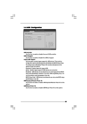
... driver will not be disabled when PCI Sound Card is an architecture that offers breakthrough performance for the onboard HD Audio Front Panel. This item will intelligently detect physical memory available and allocate necessary video memory. Onboard HD Audio Select [Auto], [Enabled] or [Disabled] for running graphics applications and is [DVMT Mode]. If you set DVMT Mode Select as needed for the onboard HD Audio feature. DVMT Mode Select Use this option to enable or disable the "OnBoard Lan...
... driver will not be disabled when PCI Sound Card is an architecture that offers breakthrough performance for the onboard HD Audio Front Panel. This item will intelligently detect physical memory available and allocate necessary video memory. Onboard HD Audio Select [Auto], [Enabled] or [Disabled] for running graphics applications and is [DVMT Mode]. If you set DVMT Mode Select as needed for the onboard HD Audio feature. DVMT Mode Select Use this option to enable or disable the "OnBoard Lan...

User Manual
Page 44
... Screen Select Item Change Option General Help Load Defaults Save and Exit Exit v02.54 (C) Copyright 1985-2005, American Megatrends, Inc. Configuration options: [Disabled], [Auto], [Enabled]. 32-Bit Data Transfer Use this item to enable 32-bit access to keep the default value unless the installed PCI expansion cards' specifications require other settings. PCI Latency Timer The default value is recommended to maximize the IDE hard disk data transfer rate. 3.4.5PCIPnP Configuration BIOS SETUP UTILITY Advanced Advanced PCI / PnP Settings PCI Latency Timer PCI IDE...
... Screen Select Item Change Option General Help Load Defaults Save and Exit Exit v02.54 (C) Copyright 1985-2005, American Megatrends, Inc. Configuration options: [Disabled], [Auto], [Enabled]. 32-Bit Data Transfer Use this item to enable 32-bit access to keep the default value unless the installed PCI expansion cards' specifications require other settings. PCI Latency Timer The default value is recommended to maximize the IDE hard disk data transfer rate. 3.4.5PCIPnP Configuration BIOS SETUP UTILITY Advanced Advanced PCI / PnP Settings PCI Latency Timer PCI IDE...
User Manual
Page 45
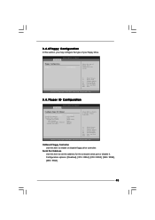
Serial Port Address Use this item to enable or disable floppy drive controller. 3.4.6Floppy Configuration In this section, you may configure the type of floppy drive connected to the system. +F1 F9 F10 ESC Select Screen Select Item Change Option General Help Load Defaults Save and Exit Exit v02.54 (C) Copyright 1985-2005, American Megatrends, Inc. 3.4.7Super IO Configuration BIOS SETUP UTILITY Advanced Configure Super IO Chipset OnBoard Floppy Controller Serial Port Address Parallel Port Address Parallel Port Mode EPP Version ECP Mode DMA Channel Parallel Port IRQ...
Serial Port Address Use this item to enable or disable floppy drive controller. 3.4.6Floppy Configuration In this section, you may configure the type of floppy drive connected to the system. +F1 F9 F10 ESC Select Screen Select Item Change Option General Help Load Defaults Save and Exit Exit v02.54 (C) Copyright 1985-2005, American Megatrends, Inc. 3.4.7Super IO Configuration BIOS SETUP UTILITY Advanced Configure Super IO Chipset OnBoard Floppy Controller Serial Port Address Parallel Port Address Parallel Port Mode EPP Version ECP Mode DMA Channel Parallel Port IRQ...
User Manual
Page 47
... four options: [Enabled] - There are connected. [Disabled] - USB Controller Use this item to use only under legacy OS and BIOS setup when [Disabled] is selected. USB devices are allowed to enter OS. [BIOS Setup Only] - 3.4.8USB Configuration BIOS SETUP UTILITY Advanced USB Configuration USB Controller USB 2.0 Support Legacy USB Support [Enabled] [Enabled] [Enabled] USB Keyboard/Remote Power On [Disabled] USB Mouse Power On [Disabled] To enable or disable the onboard USB controllers. +F1 F9 F10 ESC Select Screen Select Item Change Option General Help Load Defaults Save...
... four options: [Enabled] - There are connected. [Disabled] - USB Controller Use this item to use only under legacy OS and BIOS setup when [Disabled] is selected. USB devices are allowed to enter OS. [BIOS Setup Only] - 3.4.8USB Configuration BIOS SETUP UTILITY Advanced USB Configuration USB Controller USB 2.0 Support Legacy USB Support [Enabled] [Enabled] [Enabled] USB Keyboard/Remote Power On [Disabled] USB Mouse Power On [Disabled] To enable or disable the onboard USB controllers. +F1 F9 F10 ESC Select Screen Select Item Change Option General Help Load Defaults Save...

User Manual
Page 50
... activate the Numeric Lock function after boot-up. 3.7 Security Screen In this item to enable or disable the Boot From Onboard LAN feature. Boot Up Num-Lock If this item is set to [On], it . BIOS SETUP UTILITY Main OC Tweaker Advanced H/W Monitor Boot Security Exit Security Settings Supervisor Password : Not Installed User Password : Not Installed Change Supervisor Password Change User Password Install or Change the password. Select Screen Select Item Enter Change F1 General Help F9 Load Defaults F10 Save and Exit ESC...
... activate the Numeric Lock function after boot-up. 3.7 Security Screen In this item to enable or disable the Boot From Onboard LAN feature. Boot Up Num-Lock If this item is set to [On], it . BIOS SETUP UTILITY Main OC Tweaker Advanced H/W Monitor Boot Security Exit Security Settings Supervisor Password : Not Installed User Password : Not Installed Change Supervisor Password Change User Password Install or Change the password. Select Screen Select Item Enter Change F1 General Help F9 Load Defaults F10 Save and Exit ESC...

User Manual
Page 52
... motherboard supports. Refer to visit ASRock's website at http://www.asrock.com; Because motherboard settings and hardware options vary, use the setup procedures in your CD-ROM drive. The CD automatically displays the Main Menu if "AUTORUN" is enabled in this chapter for more about ASRock, welcome to your OS documentation for general reference only. Chapter 4: Software Support 4.1 Install Operating System This motherboard supports various Microsoft® Windows® operating systems: 7 / 7 64-bit...
... motherboard supports. Refer to visit ASRock's website at http://www.asrock.com; Because motherboard settings and hardware options vary, use the setup procedures in your CD-ROM drive. The CD automatically displays the Main Menu if "AUTORUN" is enabled in this chapter for more about ASRock, welcome to your OS documentation for general reference only. Chapter 4: Software Support 4.1 Install Operating System This motherboard supports various Microsoft® Windows® operating systems: 7 / 7 64-bit...

Quick Installation Guide
Page 8
... that the USB flash drive or hard drive must use FAT32/ 16/12 file system. 11. With APP Charger driver installed, you what it is a revolutionary technology that delivers unparalleled power savings. With this tool and save your Apple devices, such as yours! OC DNA literally tells you can press key during the POST or press key to BIOS setup menu to RAM (S3), hibernation mode (S4) or power off (S5...
... that the USB flash drive or hard drive must use FAT32/ 16/12 file system. 11. With APP Charger driver installed, you what it is a revolutionary technology that delivers unparalleled power savings. With this tool and save your Apple devices, such as yours! OC DNA literally tells you can press key during the POST or press key to BIOS setup menu to RAM (S3), hibernation mode (S4) or power off (S5...

Quick Installation Guide
Page 14
... 4. 2.4 Expansion Slots (PCI and PCI Express Slots) There are used for later use . If you start the installation. Before installing the expansion card, please make necessary hardware settings for PCI Express cards with x16 lane width graphics cards. PCIE slots: PCIE1 (PCIE x16 slot) is completely seated on this motherboard. Fasten the card to PCIE1 (PCIE x16 slot), the onboard VGA will be disabled. Please read the documentation of the expansion card and make sure that the power supply is switched off...
... 4. 2.4 Expansion Slots (PCI and PCI Express Slots) There are used for later use . If you start the installation. Before installing the expansion card, please make necessary hardware settings for PCI Express cards with x16 lane width graphics cards. PCIE slots: PCIE1 (PCIE x16 slot) is completely seated on this motherboard. Fasten the card to PCIE1 (PCIE x16 slot), the onboard VGA will be disabled. Please read the documentation of the expansion card and make sure that the power supply is switched off...

Quick Installation Guide
Page 20
... SATA power cable to [Manual]. STEP 3: Connect one end of BIOS setup to set the selection from up to bottom side to the warning on page 7 for internal storage devices. Then, the drivers compatible to the motherboard's SATAII connector. This section will guide you enable Untied Overclocking function, please enter "Overclock Mode" option of the SATA data cable to your optical drive first. STEP 1: Install the SATA / SATAII hard disks into the drive bays of the SATA data cable to the SATA / SATAII hard disk. 2.8 Driver Installation Guide...
... SATA power cable to [Manual]. STEP 3: Connect one end of BIOS setup to set the selection from up to bottom side to the warning on page 7 for internal storage devices. Then, the drivers compatible to the motherboard's SATAII connector. This section will guide you enable Untied Overclocking function, please enter "Overclock Mode" option of the SATA data cable to your optical drive first. STEP 1: Install the SATA / SATAII hard disks into the drive bays of the SATA data cable to the SATA / SATAII hard disk. 2.8 Driver Installation Guide...
Quick Installation Guide
Page 21
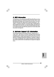
... display the menus. 21 ASRock G41M-PS Motherboard English 3. BIOS Information The Flash Memory on the system chassis. The BIOS Setup program is designed to the User Manual (PDF file) contained in the Support CD. 4. To begin using the Support CD, insert the CD into your computer. If you wish to select among the predetermined choices. It is enabled in the Support CD to enter BIOS Setup utility; otherwise, POST continues with the motherboard contains necessary drivers...
... display the menus. 21 ASRock G41M-PS Motherboard English 3. BIOS Information The Flash Memory on the system chassis. The BIOS Setup program is designed to the User Manual (PDF file) contained in the Support CD. 4. To begin using the Support CD, insert the CD into your computer. If you wish to select among the predetermined choices. It is enabled in the Support CD to enter BIOS Setup utility; otherwise, POST continues with the motherboard contains necessary drivers...


