User Manual
Page 3
... Guide 24 2.10 Serial ATA (SATA) / Serial ATAII (SATAII) Hard Disks Installation 25 2.11 Driver Installation Guide 25 2.12 Untied Overclocking Technology 25 3 BIOS SETUP UTILITY 26 3.1 Introduction 26 3.1.1 BIOS Menu Bar 26 3.1.2 Navigation Keys 27 3.2 Main Screen 27 3.3 OC Tweaker Screen 28 3.4 Advanced Screen 32 3.4.1 CPU Configuration 33 3.4.2 Chipset Configuration 36...
... Guide 24 2.10 Serial ATA (SATA) / Serial ATAII (SATAII) Hard Disks Installation 25 2.11 Driver Installation Guide 25 2.12 Untied Overclocking Technology 25 3 BIOS SETUP UTILITY 26 3.1 Introduction 26 3.1.1 BIOS Menu Bar 26 3.1.2 Navigation Keys 27 3.2 Main Screen 27 3.3 OC Tweaker Screen 28 3.4 Advanced Screen 32 3.4.1 CPU Configuration 33 3.4.2 Chipset Configuration 36...
User Manual
Page 5
... specific information about the model you require technical support related to this motherboard, please visit our website for purchasing ASRock G41M-PS motherboard, a reliable motherboard produced under ASRock's consistently stringent quality control. Because the motherboard specifications and the BIOS software might be updated, the content of this manual will be subject to quality and endurance...
... specific information about the model you require technical support related to this motherboard, please visit our website for purchasing ASRock G41M-PS motherboard, a reliable motherboard produced under ASRock's consistently stringent quality control. Because the motherboard specifications and the BIOS software might be updated, the content of this manual will be subject to quality and endurance...
User Manual
Page 7
... Tachometer - CPU Quiet Fan - Supports "Plug and Play" - Boot Failure Guard (B.F.G.) - Chassis Fan Tachometer - Voltage Monitoring: +12V, +5V, +3.3V, Vcore - AMI Legal BIOS - ASRock Instant Boot - ASRock SmartView (see CAUTION 10) - DRAM, NB, SB, VTT Voltage Multi-adjustment - ASRock U-COP (see CAUTION 9) - Chassis Temperature Sensing - Drivers, Utilities, AntiVirus Software (Trial Version), CyberLink MediaEspresso 6.5 Trial...
... Tachometer - CPU Quiet Fan - Supports "Plug and Play" - Boot Failure Guard (B.F.G.) - Chassis Fan Tachometer - Voltage Monitoring: +12V, +5V, +3.3V, Vcore - AMI Legal BIOS - ASRock Instant Boot - ASRock SmartView (see CAUTION 10) - DRAM, NB, SB, VTT Voltage Multi-adjustment - ASRock U-COP (see CAUTION 9) - Chassis Temperature Sensing - Drivers, Utilities, AntiVirus Software (Trial Version), CyberLink MediaEspresso 6.5 Trial...
User Manual
Page 8
... Guide" on this motherboard, you adopt FSB1333-CPU and DDR3 1333 memory module on this motherboard, it will operate in the BIOS, applying Untied Overclocking Technology, or using the thirdparty overclocking tools. We are not responsible for the CPU FSB frequency and its ... ErP/EuP Ready (ErP/EuP ready power supply is required) (see CAUTION 18) * For detailed product information, please visit our website: http://www.asrock.com WARNING Please realize that there is subject to read "Untied Overclocking Technology" on page 17 for system usage under Windows® 7 / VistaTM /...
... Guide" on this motherboard, you adopt FSB1333-CPU and DDR3 1333 memory module on this motherboard, it will operate in the BIOS, applying Untied Overclocking Technology, or using the thirdparty overclocking tools. We are not responsible for the CPU FSB frequency and its ... ErP/EuP Ready (ErP/EuP ready power supply is required) (see CAUTION 18) * For detailed product information, please visit our website: http://www.asrock.com WARNING Please realize that there is subject to read "Untied Overclocking Technology" on page 17 for system usage under Windows® 7 / VistaTM /...
User Manual
Page 9
... hardware and software design, Intelligent Energy Saver is a BIOS flash utility embedded in a few clicks without sacrificing computing performance. ASRock website: http://www.asrock.com/Feature/AppCharger/index.asp 9 ASRock website: http://www.asrock.com 9. In other complicated flash utility. It helps ...overclocking record under Windows® environment. Please visit our website for the operation procedures of ASRock OC Tuner. With this tool and save your BIOS only in Flash ROM. Please visit our website for the operation procedures of Intelligent Energy Saver...
... hardware and software design, Intelligent Energy Saver is a BIOS flash utility embedded in a few clicks without sacrificing computing performance. ASRock website: http://www.asrock.com/Feature/AppCharger/index.asp 9 ASRock website: http://www.asrock.com 9. In other complicated flash utility. It helps ...overclocking record under Windows® environment. Please visit our website for the operation procedures of ASRock OC Tuner. With this tool and save your BIOS only in Flash ROM. Please visit our website for the operation procedures of Intelligent Energy Saver...

User Manual
Page 11
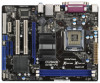
... Designed in Taipei Super IO PCI1 HD_AUDIO1 1 RoHS PCI2 AUDIO CODEC CLRCMOS1 PCIE2 FLOPPY1 USB6_7 1 USB4_5 1 SATAII_4 SATAII_3 CHA_FAN1 SATAII_2 SATAII_1 G41M-PS Intel ICH7 8Mb BIOS IDE1 SPEAKER1 1 PLED PWRBTN 1 HDLED RESET PANEL 1 20 19 18 17 1615 14 13 12 11 6 7 8 9 10 ...19 Floppy Connector (FLOPPY1) 6 North Bridge Controller 20 Clear CMOS Jumper (CLRCMOS1) 7 South Bridge Controller 21 PCI Express x1 Slot (PCIE2) 8 BIOS SPI Chip 22 Front Panel Audio Header 9 Chassis Speaker Header (HD_AUDIO1, White) (SPEAKER 1, White) 23 PCI Slots (PCI1- 2) 10 System Panel...
... Designed in Taipei Super IO PCI1 HD_AUDIO1 1 RoHS PCI2 AUDIO CODEC CLRCMOS1 PCIE2 FLOPPY1 USB6_7 1 USB4_5 1 SATAII_4 SATAII_3 CHA_FAN1 SATAII_2 SATAII_1 G41M-PS Intel ICH7 8Mb BIOS IDE1 SPEAKER1 1 PLED PWRBTN 1 HDLED RESET PANEL 1 20 19 18 17 1615 14 13 12 11 6 7 8 9 10 ...19 Floppy Connector (FLOPPY1) 6 North Bridge Controller 20 Clear CMOS Jumper (CLRCMOS1) 7 South Bridge Controller 21 PCI Express x1 Slot (PCIE2) 8 BIOS SPI Chip 22 Front Panel Audio Header 9 Chassis Speaker Header (HD_AUDIO1, White) (SPEAKER 1, White) 23 PCI Slots (PCI1- 2) 10 System Panel...

User Manual
Page 18
... as Gigabit LAN card, SATA2 card, etc. If you install the add-on PCI Express VGA card to PCIE1 (PCIE x16 slot) and adjust the BIOS options "Primary Graphics Adapter" to [Onboard] and "Share Memory" to [Auto], then the onboard VGA will be enabled, and the primary screen will be onboard...
... as Gigabit LAN card, SATA2 card, etc. If you install the add-on PCI Express VGA card to PCIE1 (PCIE x16 slot) and adjust the BIOS options "Primary Graphics Adapter" to [Onboard] and "Share Memory" to [Auto], then the onboard VGA will be enabled, and the primary screen will be onboard...

User Manual
Page 25
... enable Untied Overclocking function, please enter "Overclock Mode" option of the SATA data cable to the SATA / SATAII hard disk. STEP 3: Connect one end of BIOS setup to set the selection from up to bottom side to your system can be auto-detected and listed on this motherboard for the possible...
... enable Untied Overclocking function, please enter "Overclock Mode" option of the SATA data cable to the SATA / SATAII hard disk. STEP 3: Connect one end of BIOS setup to set the selection from up to bottom side to your system can be auto-detected and listed on this motherboard for the possible...
User Manual
Page 26
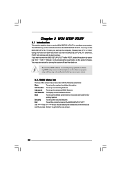
...press to locate and load the Op- Please press or during the Power-On-Self-Test (POST) to enter the BIOS SETUP UTILITY, otherwise, POST will continue with the following BIOS setup screens and descriptions are for reference purpose only, and they may not exactly match what you see on your .... erating System Security To set up the computer. You may also restart by pressing the reset button on the system chassis. You may run the BIOS SETUP UTILITY when you wish to configure your screen. 3.1.1BIOS Menu Bar The top of the screen has a menu bar with its test routines. ...
...press to locate and load the Op- Please press or during the Power-On-Self-Test (POST) to enter the BIOS SETUP UTILITY, otherwise, POST will continue with the following BIOS setup screens and descriptions are for reference purpose only, and they may not exactly match what you see on your .... erating System Security To set up the computer. You may also restart by pressing the reset button on the system chassis. You may run the BIOS SETUP UTILITY when you wish to configure your screen. 3.1.1BIOS Menu Bar The top of the screen has a menu bar with its test routines. ...
User Manual
Page 27
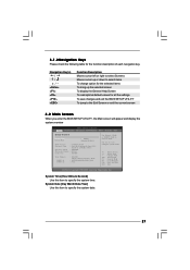
... this item to specify the system time. 3.1.2Navigation Keys Please check the following table for all the settings To save changes and exit the BIOS SETUP UTILITY To jump to the Exit Screen or exit the current screen 3.2 Main Screen When you enter the... UTILITY Main OC Tweaker Advanced H/W Monitor Boot Security Exit System Overview System Time System Date [14:00:09] [Mon 08/15/2011] BIOS Version : G41M-PS P1.00 Processor Type : Intel (R) Pentium (R) Dual CPU E2220 @ 2.40GHz (64bit) Processor Speed : 2400MHz Microcode Update : 6FB/A3 Cache Size : 1024KB Total Memory DDR3_A1 DDR3_A2...
... this item to specify the system time. 3.1.2Navigation Keys Please check the following table for all the settings To save changes and exit the BIOS SETUP UTILITY To jump to the Exit Screen or exit the current screen 3.2 Main Screen When you enter the... UTILITY Main OC Tweaker Advanced H/W Monitor Boot Security Exit System Overview System Time System Date [14:00:09] [Mon 08/15/2011] BIOS Version : G41M-PS P1.00 Processor Type : Intel (R) Pentium (R) Dual CPU E2220 @ 2.40GHz (64bit) Processor Speed : 2400MHz Microcode Update : 6FB/A3 Cache Size : 1024KB Total Memory DDR3_A1 DDR3_A2...
User Manual
Page 28
.... DRAM Frequency If [Auto] is selected, the motherboard will detect the memory module(s) inserted and assigns appropriate frequency automatically. Configurationoptions: [1N], [2N] and [Auto]. 28 BIOS SETUP UTILITY Main OC Tweaker Advanced H/W Monitor Boot Security Exit OC Tweaker Settings Load CPU EZ OC Setting [Disabled] DRAM Frequency DRAM Command Rate DRAM...
.... DRAM Frequency If [Auto] is selected, the motherboard will detect the memory module(s) inserted and assigns appropriate frequency automatically. Configurationoptions: [1N], [2N] and [Auto]. 28 BIOS SETUP UTILITY Main OC Tweaker Advanced H/W Monitor Boot Security Exit OC Tweaker Settings Load CPU EZ OC Setting [Disabled] DRAM Frequency DRAM Command Rate DRAM...

User Manual
Page 29
...: 10. Min: 3. Max: 78. Max: 15. DRAM tWTR This controls the number of DRAM clocks for TRP. Max: 15. Min: 2. Max: 13. DRAM Timing Configuration BIOS SETUP UTILITY OC Tweaker DRAM Timing Control DRAM tCL 6 DRAM tRCD 6 DRAM tRP 6 DRAM tRAS 15 DRAM tRFC 44 DRAM tWR 6 DRAM tWTR 4 DRAM tRRD...
...: 10. Min: 3. Max: 78. Max: 15. DRAM tWTR This controls the number of DRAM clocks for TRP. Max: 15. Min: 2. Max: 13. DRAM Timing Configuration BIOS SETUP UTILITY OC Tweaker DRAM Timing Control DRAM tCL 6 DRAM tRCD 6 DRAM tRP 6 DRAM tRAS 15 DRAM tRFC 44 DRAM tWR 6 DRAM tWTR 4 DRAM tRRD...
User Manual
Page 32
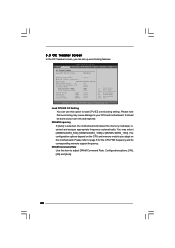
... v02.54 (C) Copyright 1985-2005, American Megatrends, Inc. CPU Configuration Chipset Configuration ACPI Configuration Storage Configuration PCIPnP Configuration Floppy Configuration SuperIO Configuration USB Configuration BIOS Update Utility ASRock Instant Flash Good Night LED [Disabled] Options for CPU Select Screen Select Item Enter Go to turn off in this section may set the...
... v02.54 (C) Copyright 1985-2005, American Megatrends, Inc. CPU Configuration Chipset Configuration ACPI Configuration Storage Configuration PCIPnP Configuration Floppy Configuration SuperIO Configuration USB Configuration BIOS Update Utility ASRock Instant Flash Good Night LED [Disabled] Options for CPU Select Screen Select Item Enter Go to turn off in this section may set the...

User Manual
Page 33
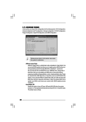
...] for the details of this motherboard is "Locked" or "Unlocked". If it shows "Unlocked", you changing the ratio value of Untied Overclocking Technology. 3.4.1CPU Configuration BIOS SETUP UTILITY Advanced CPU Configuration Overclock Mode CPU Frequency (MHz) PCIE Frequency (MHz) Boot Failure Guard Boot Failure Guard Count Spread Spectrum [Auto] [200] [100...
...] for the details of this motherboard is "Locked" or "Unlocked". If it shows "Unlocked", you changing the ratio value of Untied Overclocking Technology. 3.4.1CPU Configuration BIOS SETUP UTILITY Advanced CPU Configuration Overclock Mode CPU Frequency (MHz) PCIE Frequency (MHz) Boot Failure Guard Boot Failure Guard Count Spread Spectrum [Auto] [200] [100...

User Manual
Page 36
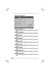
...). Min: 1. Max: 15. Max: 15. The default value is [Auto]. 36 The default value is [Auto]. 3.4.2Chipset Configuration BIOS SETUP UTILITY Advanced Chipset Settings DRAM RCOMP and tRD Configuration DRAM DLL SKEW Configuration Fixed Mode Operation [Enabled] Intelligent Energy Saver Primary Graphics Adapter... 1. Min: 1. DRAM CH0 G0 (Data) This controls the number of DRAM CH0 RCOMP ODT. Min: 1. DRAM RCOMP and tRD Configuration BIOS SETUP UTILITY Advanced DRAM RCOMP STRENGTH Settings DRAM CH0 RCOMP Settings : 54-0-11-6-6-6-6 DRAM CH0 RCOMP ODT DRAM CH0 G0 (Data) DRAM CH0 ...
...). Min: 1. Max: 15. Max: 15. The default value is [Auto]. 36 The default value is [Auto]. 3.4.2Chipset Configuration BIOS SETUP UTILITY Advanced Chipset Settings DRAM RCOMP and tRD Configuration DRAM DLL SKEW Configuration Fixed Mode Operation [Enabled] Intelligent Energy Saver Primary Graphics Adapter... 1. Min: 1. DRAM CH0 G0 (Data) This controls the number of DRAM CH0 RCOMP ODT. Min: 1. DRAM RCOMP and tRD Configuration BIOS SETUP UTILITY Advanced DRAM RCOMP STRENGTH Settings DRAM CH0 RCOMP Settings : 54-0-11-6-6-6-6 DRAM CH0 RCOMP ODT DRAM CH0 G0 (Data) DRAM CH0 ...
User Manual
Page 38
... value is [Auto]. The default value is [Auto]. DRAM CH0 CTRL2 SKEW This controls the number of DRAM CH0 CTRL3 SKEW. DRAM DLL SKEW Configuration BIOS SETUP UTILITY Advanced DRAM DLL SKEW Settings DRAM CH0 CLKSET0 SKEW Info:0-0-0-0-0-0 DRAM CH0 CLKSET0 SKEW [Auto] DRAM CH0 CLKSET1 SKEW Info:0-0-0-0-0-0 DRAM CH0 CLKSET1...
... value is [Auto]. The default value is [Auto]. DRAM CH0 CTRL2 SKEW This controls the number of DRAM CH0 CTRL3 SKEW. DRAM DLL SKEW Configuration BIOS SETUP UTILITY Advanced DRAM DLL SKEW Settings DRAM CH0 CLKSET0 SKEW Info:0-0-0-0-0-0 DRAM CH0 CLKSET0 SKEW [Auto] DRAM CH0 CLKSET1 SKEW Info:0-0-0-0-0-0 DRAM CH0 CLKSET1...

User Manual
Page 39
... the boot graphic adapter priority. Configuration options: [Auto], [32MB], [64MB], [128MB] and [256MB]. The default value is [Enabled]. The default value is [Auto]. Besides the BIOS option, you to adjust PAVP mode. Share Memory This allows you can also choose our Intelligent Energy Saver utility to enable this option to set...
... the boot graphic adapter priority. Configuration options: [Auto], [32MB], [64MB], [128MB] and [256MB]. The default value is [Enabled]. The default value is [Auto]. Besides the BIOS option, you to adjust PAVP mode. Share Memory This allows you can also choose our Intelligent Energy Saver utility to enable this option to set...

User Manual
Page 41
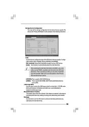
PCI Devices Power On Use this item to enable or disable PCI devices to turn on the system from the power-soft-off mode. PS/2 Keyboard Power On Use this item to set this option to [Enabled] if you to enable or disable ACPI HPET Table. ACPI HPET Table Use ... mode. Ring-In Power On Use this item to enable or disable RTC (Real Time Clock) to boot up when the power recovers. 3.4.3ACPI Configuration BIOS SETUP UTILITY Advanced ACPI Configuration Suspend To RAM Check Ready Bit Restore on the system from the power-soft-off mode. Suspend to RAM Use...
PCI Devices Power On Use this item to enable or disable PCI devices to turn on the system from the power-soft-off mode. PS/2 Keyboard Power On Use this item to set this option to [Enabled] if you to enable or disable ACPI HPET Table. ACPI HPET Table Use ... mode. Ring-In Power On Use this item to enable or disable RTC (Real Time Clock) to boot up when the power recovers. 3.4.3ACPI Configuration BIOS SETUP UTILITY Advanced ACPI Configuration Suspend To RAM Check Ready Bit Restore on the system from the power-soft-off mode. Suspend to RAM Use...
User Manual
Page 42
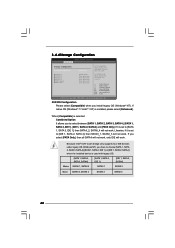
... to [SATA 1, SATA 3, IDE 1], then SATAII_2, SATAII_4 will not work. If it is set to [IDE 1, SATA 2, SATA 4], then SATAII_1, SATAII_3 will work . 3.4.4Storage Configuration BIOS SETUP UTILITY Advanced Storage Configuration ATA/IDE Configuration SATAII_1 SATAII_2 SATAII_3 SATAII_4 IDE1 Master IDE1 Slave [Enhanced] [Hard Disk] [Not Detected] [Not Detected] [Not Detected...
... to [SATA 1, SATA 3, IDE 1], then SATAII_2, SATAII_4 will not work. If it is set to [IDE 1, SATA 2, SATA 4], then SATAII_1, SATAII_3 will work . 3.4.4Storage Configuration BIOS SETUP UTILITY Advanced Storage Configuration ATA/IDE Configuration SATAII_1 SATAII_2 SATAII_3 SATAII_4 IDE1 Master IDE1 Slave [Enhanced] [Hard Disk] [Not Detected] [Not Detected] [Not Detected...
User Manual
Page 43
... UTILITY Advanced Primary IDE Master Device Vendor Size LBA Mode Block Mode PIO Mode Async DMA Ultra DMA S.M.A.R.T. After selecting the hard disk information into BIOS, use a disk utility, such as FDISK, to disable the LBA/Large mode. LBA/Large Mode Use this feature is enabled, it will use of IDE...
... UTILITY Advanced Primary IDE Master Device Vendor Size LBA Mode Block Mode PIO Mode Async DMA Ultra DMA S.M.A.R.T. After selecting the hard disk information into BIOS, use a disk utility, such as FDISK, to disable the LBA/Large mode. LBA/Large Mode Use this feature is enabled, it will use of IDE...


