User Manual
Page 4
4 Software Support 51 4.1 Install Operating System 51 4.2 Support CD Information 51 4.2.1 Running Support CD 51 4.2.2 Drivers Menu 51 4.2.3 Utilities Menu 51 4.2.4 Contact Information 51 4
4 Software Support 51 4.1 Install Operating System 51 4.2 Support CD Information 51 4.2.1 Running Support CD 51 4.2.2 Drivers Menu 51 4.2.3 Utilities Menu 51 4.2.4 Contact Information 51 4
User Manual
Page 5
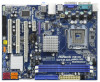
... version will be available on ASRock website as well. ASRock website http://www.asrock.com If you are using. In case any modifications of the Support CD. www.asrock.com/support/index.asp 1.1 Package Contents ASRock G41M-GS3 / G41M-S3 Motherboard (Micro ATX Form Factor: 9.6-in x 7.6-in, 24.4 cm x 19.3 cm) ASRock G41M-GS3 / G41M-S3 Quick Installation Guide ASRock G41M-GS3 / G41M-S3 Support CD Two Serial ATA...
... version will be available on ASRock website as well. ASRock website http://www.asrock.com If you are using. In case any modifications of the Support CD. www.asrock.com/support/index.asp 1.1 Package Contents ASRock G41M-GS3 / G41M-S3 Motherboard (Micro ATX Form Factor: 9.6-in x 7.6-in, 24.4 cm x 19.3 cm) ASRock G41M-GS3 / G41M-S3 Quick Installation Guide ASRock G41M-GS3 / G41M-S3 Support CD Two Serial ATA...
User Manual
Page 6
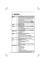
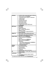
Supports EM64T CPU - Supports D-Sub with LED (ACT/LINK LED and SPEED LED) - G41M-S3: Realtek PCIE x1 LAN 8103EL / 8102EL, speed 10/100 Mb/s - HD Audio Jack: Line in , 24.4 cm x 19.3 cm - Northbridge: Intel® G41 -... Pixel Shader 4.0, DirectX 10 - capacity of system memory: 8GB (see CAUTION 2) - resolution up to -Use USB 2.0 Ports - 1 x RJ-45 LAN Port with max. G41M-GS3: Realtek PCIE x1 Gigabit LAN RTL8111DL, speed 10/100/1000 Mb/s - Supports Hyper-Threading Technology (see CAUTION 6) - 1 x PCI Express x16 slot - 1 x PCI Express x1 slot - 2 x PCI slots...
Supports EM64T CPU - Supports D-Sub with LED (ACT/LINK LED and SPEED LED) - G41M-S3: Realtek PCIE x1 LAN 8103EL / 8102EL, speed 10/100 Mb/s - HD Audio Jack: Line in , 24.4 cm x 19.3 cm - Northbridge: Intel® G41 -... Pixel Shader 4.0, DirectX 10 - capacity of system memory: 8GB (see CAUTION 2) - resolution up to -Use USB 2.0 Ports - 1 x RJ-45 LAN Port with max. G41M-GS3: Realtek PCIE x1 Gigabit LAN RTL8111DL, speed 10/100/1000 Mb/s - Supports Hyper-Threading Technology (see CAUTION 6) - 1 x PCI Express x16 slot - 1 x PCI Express x1 slot - 2 x PCI slots...
User Manual
Page 7
AMI Legal BIOS - CPU, VCCM, NB, SB,VTT Voltage Multi-adjustment - ASRock OC DNA (see CAUTION 11) - Chassis Temperature Sensing - FCC, CE - Supports Smart BIOS Support CD - Instant Boot - Hybrid Booster: - AMBIOS 2.3.1 Support - Intelligent Energy Saver (see CAUTION 13) - ASRock U-COP (see CAUTION 10) - CPU Fan Tachometer - ACPI 1.1 Compliance Wake Up Events - Drivers, Utilities, AntiVirus Software...
AMI Legal BIOS - CPU, VCCM, NB, SB,VTT Voltage Multi-adjustment - ASRock OC DNA (see CAUTION 11) - Chassis Temperature Sensing - FCC, CE - Supports Smart BIOS Support CD - Instant Boot - Hybrid Booster: - AMBIOS 2.3.1 Support - Intelligent Energy Saver (see CAUTION 13) - ASRock U-COP (see CAUTION 10) - CPU Fan Tachometer - ACPI 1.1 Compliance Wake Up Events - Drivers, Utilities, AntiVirus Software...
User Manual
Page 8
... / XP 64-bit / XP SP1 or SP2. 8 Please read "Untied Overclocking Technology" on page 16 for proper jumper settings. 6. This motherboard supports Dual Channel Memory Technology. Before you adopt a DDR3 1333 memory module on page 24 to adjust your SATAII hard disk drive to adjust the jumpers... 8. Due to page 19 for proper installation. 5. Please check Intel® website for the CPU FSB frequency and its corresponding memory support frequency. Overclocking may be done at DDR3 533 if you adopt a DDR3 800 memory module. * If you implement Dual Channel Memory Technology...
... / XP 64-bit / XP SP1 or SP2. 8 Please read "Untied Overclocking Technology" on page 16 for proper jumper settings. 6. This motherboard supports Dual Channel Memory Technology. Before you adopt a DDR3 1333 memory module on page 24 to adjust your SATAII hard disk drive to adjust the jumpers... 8. Due to page 19 for proper installation. 5. Please check Intel® website for the CPU FSB frequency and its corresponding memory support frequency. Overclocking may be done at DDR3 533 if you adopt a DDR3 800 memory module. * If you implement Dual Channel Memory Technology...
User Manual
Page 14
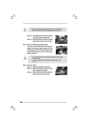
... proper inserting, please ensure to assist in removal. 1. Step 3. Remove PnP Cap (Pick and Place Cap): Use your left hand index finger and thumb to support the load plate edge, engage PnP cap with right hand thumb and peel the cap from the socket while pressing on load plate, engage the...
... proper inserting, please ensure to assist in removal. 1. Step 3. Remove PnP Cap (Pick and Place Cap): Use your left hand index finger and thumb to support the load plate edge, engage PnP cap with right hand thumb and peel the cap from the socket while pressing on load plate, engage the...
User Manual
Page 15
... the CPU and the heatsink are oriented on side closest to the CPU fan connector on the motherboard (CPU_FAN1, see page 10, No. 4). Ensure that supports Intel 775-LAND CPU. Step 1. Place the heatsink onto the socket. Then connect the CPU fan to the CPU_FAN connector (CPU_FAN1, see page 10, No...
... the CPU and the heatsink are oriented on side closest to the CPU fan connector on the motherboard (CPU_FAN1, see page 10, No. 4). Ensure that supports Intel 775-LAND CPU. Step 1. Place the heatsink onto the socket. Then connect the CPU fan to the CPU_FAN connector (CPU_FAN1, see page 10, No...
User Manual
Page 16
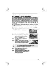
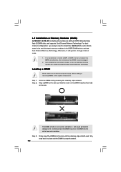
... such that the notch on the DIMM matches the break on the slot. 2.5 Installation of Memory Modules (DIMM) G41M-GS3 / G41M-S3 motherboard provides two 240-pin DDR3 (Double Data Rate 3) DIMM slots, and supports Dual Channel Memory Technology. notch break notch break The DIMM only fits in one memory module or two non...
... such that the notch on the DIMM matches the break on the slot. 2.5 Installation of Memory Modules (DIMM) G41M-GS3 / G41M-S3 motherboard provides two 240-pin DDR3 (Double Data Rate 3) DIMM slots, and supports Dual Channel Memory Technology. notch break notch break The DIMM only fits in one memory module or two non...
User Manual
Page 20
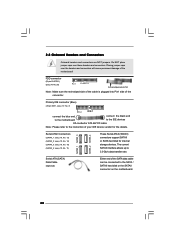
... red-striped side to the instruction of the connector. Primary IDE connector (Blue) (39-pin IDE1, see p.10, No. 11) These Serial ATAII (SATAII) connectors support SATAII or SATA hard disk for the details. Serial ATA (SATA) Data Cable (Optional) Either end of the motherboard! SATAII_1 SATAII_3 SATAII_2 SATAII_4 Serial ATAII...
... red-striped side to the instruction of the connector. Primary IDE connector (Blue) (39-pin IDE1, see p.10, No. 11) These Serial ATAII (SATAII) connectors support SATAII or SATA hard disk for the details. Serial ATA (SATA) Data Cable (Optional) Either end of the motherboard! SATAII_1 SATAII_3 SATAII_2 SATAII_4 Serial ATAII...

User Manual
Page 21
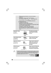
... port cable that allows convenient connection and control of printer devices. Set the Front Panel Control option from [Auto] to MIC2_L. Each USB 2.0 header can support two USB 2.0 ports. 1 GND P+4 P-4 USB_PWR Print Port Header (25-pin LPT1) (see p.10 No. 25) AFD# ERROR# PINIT# SLIN# GND 1 SPD7 SPD6 ACK# ...'97 audio panel, please install it to enter Realtek HD Audio Manager. D. MIC_RET and OUT_RET are two USB 2.0 headers on the chassis must support HDA to function correctly. E. Click the icon on the lower right hand taskbar to the front panel audio header as below: A.
... port cable that allows convenient connection and control of printer devices. Set the Front Panel Control option from [Auto] to MIC2_L. Each USB 2.0 header can support two USB 2.0 ports. 1 GND P+4 P-4 USB_PWR Print Port Header (25-pin LPT1) (see p.10 No. 25) AFD# ERROR# PINIT# SLIN# GND 1 SPD7 SPD6 ACK# ...'97 audio panel, please install it to enter Realtek HD Audio Manager. D. MIC_RET and OUT_RET are two USB 2.0 headers on the chassis must support HDA to function correctly. E. Click the icon on the lower right hand taskbar to the front panel audio header as below: A.
User Manual
Page 22
... clicking "OK". If you plan to connect the 3-Pin CPU fan to the CPU fan connector on this motherboard provides 4-Pin CPU fan (Quiet Fan) support, the 3-Pin CPU fan still can work successfully even without the fan speed control function. Please connect the chassis speaker to the ground pin. CPU...
... clicking "OK". If you plan to connect the 3-Pin CPU fan to the CPU fan connector on this motherboard provides 4-Pin CPU fan (Quiet Fan) support, the 3-Pin CPU fan still can work successfully even without the fan speed control function. Please connect the chassis speaker to the ground pin. CPU...
User Manual
Page 24
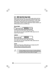
Western Digital 7531 8642 If pin 5 and pin 6 are just for details: http://www.hitachigst.com/hdd/support/download.htm The above examples are shorted, SATA 1.5Gb/s will be at SATAII mode. On the other hand, if you want to enable SATAII 3.0Gb/s, ...
Western Digital 7531 8642 If pin 5 and pin 6 are just for details: http://www.hitachigst.com/hdd/support/download.htm The above examples are shorted, SATA 1.5Gb/s will be at SATAII mode. On the other hand, if you want to enable SATAII 3.0Gb/s, ...
User Manual
Page 25
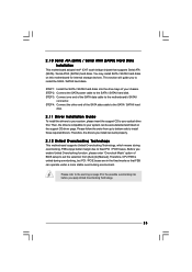
Please refer to the warning on page 8 for internal storage devices. You may install SATA / SATAII hard disks on the support CD driver page. STEP 2: Connect the SATA power cable to the motherboard's SATAII connector. STEP 4: Connect the other end of the SATA data cable to ... of the SATA data cable to the SATA / SATAII hard disk. 2.11 Driver Installation Guide To install the drivers to your system, please insert the support CD to [Manual]. Please follow the order from [Auto] to your system can be auto-detected and listed on this motherboard for the possible overclocking...
Please refer to the warning on page 8 for internal storage devices. You may install SATA / SATAII hard disks on the support CD driver page. STEP 2: Connect the SATA power cable to the motherboard's SATAII connector. STEP 4: Connect the other end of the SATA data cable to ... of the SATA data cable to the SATA / SATAII hard disk. 2.11 Driver Installation Guide To install the drivers to your system, please insert the support CD to [Manual]. Please follow the order from [Auto] to your system can be auto-detected and listed on this motherboard for the possible overclocking...
User Manual
Page 29
... ESC Exit v02.54 (C) Copyright 1985-2005, American Megatrends, Inc. You may cause damage to page 8 for the CPU FSB frequency and its corresponding memory support frequency. The configuration options depend on the CPU and memory module you can use this option to your own risk and expense. Select Screen Select...
... ESC Exit v02.54 (C) Copyright 1985-2005, American Megatrends, Inc. You may cause damage to page 8 for the CPU FSB frequency and its corresponding memory support frequency. The configuration options depend on the CPU and memory module you can use this option to your own risk and expense. Select Screen Select...

User Manual
Page 31
If the CPU you adopt supports EIST (Intel (R) SpeedStep(tm) tech.), and you changing the ratio value of this option to adjust the ratio value, please disable the option " Intel (R) SpeedStep(...) tech. This item will find this function. The default value of this feature is unlocked, you will be hidden if the current CPU does not support Intel (R) SpeedStep(tm) tech.. Processor can switch between multiple frequency and voltage points to [Enabled]. If you changing the ratio value of this to [1.353V...
If the CPU you adopt supports EIST (Intel (R) SpeedStep(tm) tech.), and you changing the ratio value of this option to adjust the ratio value, please disable the option " Intel (R) SpeedStep(...) tech. This item will find this function. The default value of this feature is unlocked, you will be hidden if the current CPU does not support Intel (R) SpeedStep(tm) tech.. Processor can switch between multiple frequency and voltage points to [Enabled]. If you changing the ratio value of this to [1.353V...

User Manual
Page 33
...Use this item appear to adjust PCIE frequency. If it shows "Unlocked", you changing the ratio value of this motherboard. Enhance Halt State All processors support the Halt State (C1). Cnfiguration options: [Auto], [Manual] and [Optimized]. CPU Frequency (MHz) Use this option to allow you will find...Ratio CMOS Setting appears to adjust CPU frequency. Spread Spectrum This item should be [Auto] for better system stability. If the CPU you adopt supports EIST (Intel (R) SpeedStep(tm) tech.), and you will find this to enable or disable the "Enhanced Halt State". +F1 F9 F10 ...
...Use this item appear to adjust PCIE frequency. If it shows "Unlocked", you changing the ratio value of this motherboard. Enhance Halt State All processors support the Halt State (C1). Cnfiguration options: [Auto], [Manual] and [Optimized]. CPU Frequency (MHz) Use this option to allow you will find...Ratio CMOS Setting appears to adjust CPU frequency. Spread Spectrum This item should be [Auto] for better system stability. If the CPU you adopt supports EIST (Intel (R) SpeedStep(tm) tech.), and you will find this to enable or disable the "Enhanced Halt State". +F1 F9 F10 ...
User Manual
Page 34
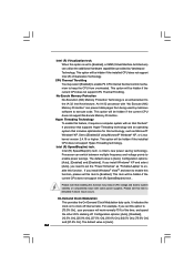
...to set this function. This option will be hidden if the installed CPU does not support Intel (R) Virtualization Technology. This option will be hidden if the installed CPU does not support Hyper-Threading technology. On-Demand Clock Modulation This provides the On-Demand Clock Modulation ... VistaTM and want to enable this function, please set to system stability or compatibility issue with an Intel Pentium® 4 processor that supports Hyper-Threading technology and an operating system that enabling this item to clock off . It indicates the clock on to [Enabled]. Intel ...
...to set this function. This option will be hidden if the installed CPU does not support Intel (R) Virtualization Technology. This option will be hidden if the installed CPU does not support Hyper-Threading technology. On-Demand Clock Modulation This provides the On-Demand Clock Modulation ... VistaTM and want to enable this function, please set to system stability or compatibility issue with an Intel Pentium® 4 processor that supports Hyper-Threading technology and an operating system that enabling this item to clock off . It indicates the clock on to [Enabled]. Intel ...

User Manual
Page 39
... offers breakthrough performance for the onboard HD Audio feature. The default value is [DVMT Mode]. Share Memory This allows you to enable this option to support increased content protection and robustness requirements for premium content playback (Bluray disc). [Lite] mode is the encryption of compressed video buffer and is the new...
... offers breakthrough performance for the onboard HD Audio feature. The default value is [DVMT Mode]. Share Memory This allows you to enable this option to support increased content protection and robustness requirements for premium content playback (Bluray disc). [Lite] mode is the encryption of compressed video buffer and is the new...
User Manual
Page 41
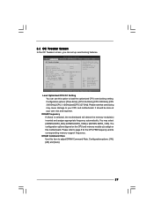
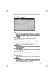
.../Power Loss This allows you set the power state after an unexpected AC/Power loss. Ring-In Power On Use this feature if the OS supports it. The default value is selected, the AC/Power remains off when the power recovers.
.../Power Loss This allows you set the power state after an unexpected AC/Power loss. Ring-In Power On Use this feature if the OS supports it. The default value is selected, the AC/Power remains off when the power recovers.
User Manual
Page 42
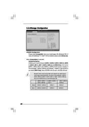
... OS (Windows® NT). If it is set to [SATA 1, SATA 3, IDE 1], then SATAII_2, SATAII_4 will not work. Because Intel® ICH7 south bridge only supports four IDE devices under legacy OS (Windows NT), you select [PATA Only], then all SATAII will not work, only IDE will not work . Likewise, if...
... OS (Windows® NT). If it is set to [SATA 1, SATA 3, IDE 1], then SATAII_2, SATAII_4 will not work. Because Intel® ICH7 south bridge only supports four IDE devices under legacy OS (Windows NT), you select [PATA Only], then all SATAII will not work, only IDE will not work . Likewise, if...


