User Manual
Page 3
...(SATA) / Serial ATAII (SATAII) Hard Disks Installation 25 2.11 Driver Installation Guide 25 2.12 Untied Overclocking Technology 25 3 BIOS SETUP UTILITY 26 3.1 Introduction 26 3.1.1 BIOS Menu Bar 26 3.1.2 Navigation Keys 27 3.2 Main Screen 27 3.3 OC Tweaker Screen 29 3.4 Advanced Screen 32 3.4.1 CPU Configuration 33 3.4.2 Chipset Configuration 35 3.4.3 ACPI Configuration 41 3.4.4 Storage Configuration 42 3.4.5 PCIPnP Configuration 44 3.4.6 Floppy Configuration 45 3.4.7 Super IO Configuration 45 3.4.8 USB Configuration 46 3.5 Hardware Health Event Monitoring Screen 47 3.6 Boot...
...(SATA) / Serial ATAII (SATAII) Hard Disks Installation 25 2.11 Driver Installation Guide 25 2.12 Untied Overclocking Technology 25 3 BIOS SETUP UTILITY 26 3.1 Introduction 26 3.1.1 BIOS Menu Bar 26 3.1.2 Navigation Keys 27 3.2 Main Screen 27 3.3 OC Tweaker Screen 29 3.4 Advanced Screen 32 3.4.1 CPU Configuration 33 3.4.2 Chipset Configuration 35 3.4.3 ACPI Configuration 41 3.4.4 Storage Configuration 42 3.4.5 PCIPnP Configuration 44 3.4.6 Floppy Configuration 45 3.4.7 Super IO Configuration 45 3.4.8 USB Configuration 46 3.5 Hardware Health Event Monitoring Screen 47 3.6 Boot...
User Manual
Page 7
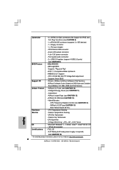
...- Front panel audio connector - 2 x USB 2.0 headers (support 4 USB 2.0 ports) (see CAUTION 14) - CPU, VCCM, NB, SB,VTT Voltage Multi-adjustment - CPU Frequency Stepless Control (see CAUTION 9) BIOS Feature - 8Mb AMI BIOS - Chassis Fan Tachometer - ACPI 1.1 Compliance Wake Up Events - ASRock Instant Flash (see CAUTION 8) - 1 x ATA100 IDE connector (supports 2 x IDE devices) - 1 x Floppy connector - 1 x Print port header - CPU Quiet Fan - CPU/Chassis FAN connector - 24 pin ATX power connector - 4 pin 12V power connector - AMI Legal BIOS - AMBIOS 2.3.1 Support...
...- Front panel audio connector - 2 x USB 2.0 headers (support 4 USB 2.0 ports) (see CAUTION 14) - CPU, VCCM, NB, SB,VTT Voltage Multi-adjustment - CPU Frequency Stepless Control (see CAUTION 9) BIOS Feature - 8Mb AMI BIOS - Chassis Fan Tachometer - ACPI 1.1 Compliance Wake Up Events - ASRock Instant Flash (see CAUTION 8) - 1 x ATA100 IDE connector (supports 2 x IDE devices) - 1 x Floppy connector - 1 x Print port header - CPU Quiet Fan - CPU/Chassis FAN connector - 24 pin ATX power connector - 4 pin 12V power connector - AMI Legal BIOS - AMBIOS 2.3.1 Support...
User Manual
Page 9
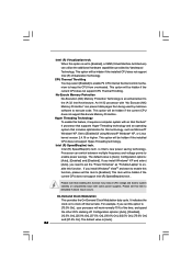
... USB flash drive, floppy disk or hard drive, then you resume the system, please check if the CPU fan on the same motherboard. 14. Just launch this tool and save the new BIOS file to update system BIOS without preparing an additional floppy diskette or other complicated flash utility. Although this utility, you what it is a BIOS flash utility embedded in a few clicks without entering operating systems first like MS-DOS or Windows...
... USB flash drive, floppy disk or hard drive, then you resume the system, please check if the CPU fan on the same motherboard. 14. Just launch this tool and save the new BIOS file to update system BIOS without preparing an additional floppy diskette or other complicated flash utility. Although this utility, you what it is a BIOS flash utility embedded in a few clicks without entering operating systems first like MS-DOS or Windows...

User Manual
Page 10
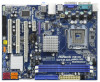
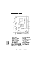
... CPU Socket 16 USB 2.0 Header (USB4_5, Blue) 3 North Bridge Controller 17 System Panel Header (PANEL1, Orange) 4 CPU Fan Connector (CPU_FAN1) 18 BIOS SPI Chip 5 2 x 240-pin DDR3 DIMM Slots 19 Chassis Fan Connector (CHA_FAN1) (Dual Channel: DDR3_A1, DDR3_B1; Red) 26 FSB1 / FSB2 / FSB3 Jumper 13 Primary SATAII Connector (SATAII_1; Blue) 20 Floppy Connector (FLOPPY1) 6 ATX Power Connector (ATXPWR1) 21 Front Panel Audio Header 7 IDE1 Connector (IDE1, Blue) (HD_AUDIO1, Lime) 8 Clear CMOS Jumper (CLRCMOS1) 22 PCI Slots (PCI1- 2) 9 South Bridge Controller 23 PCI Express...
... CPU Socket 16 USB 2.0 Header (USB4_5, Blue) 3 North Bridge Controller 17 System Panel Header (PANEL1, Orange) 4 CPU Fan Connector (CPU_FAN1) 18 BIOS SPI Chip 5 2 x 240-pin DDR3 DIMM Slots 19 Chassis Fan Connector (CHA_FAN1) (Dual Channel: DDR3_A1, DDR3_B1; Red) 26 FSB1 / FSB2 / FSB3 Jumper 13 Primary SATAII Connector (SATAII_1; Blue) 20 Floppy Connector (FLOPPY1) 6 ATX Power Connector (ATXPWR1) 21 Front Panel Audio Header 7 IDE1 Connector (IDE1, Blue) (HD_AUDIO1, Lime) 8 Clear CMOS Jumper (CLRCMOS1) 22 PCI Slots (PCI1- 2) 9 South Bridge Controller 23 PCI Express...

User Manual
Page 21
... Besides four default USB 2.0 ports on this motherboard. B. Set the Front Panel Control option from [Auto] to the front panel audio header as below: A. Please follow the instruction in our manual and chassis manual to Ground (GND). Enter BIOS Setup Utility. Enter Windows system. Connect Ground (GND) to install your system. 2. E. For Windows® XP / XP 64-bit OS: Click "Audio I /O panel, there are for AC'97 audio panel. Click the icon on the chassis must support HDA to enter Realtek HD Audio Manager...
... Besides four default USB 2.0 ports on this motherboard. B. Set the Front Panel Control option from [Auto] to the front panel audio header as below: A. Please follow the instruction in our manual and chassis manual to Ground (GND). Enter BIOS Setup Utility. Enter Windows system. Connect Ground (GND) to install your system. 2. E. For Windows® XP / XP 64-bit OS: Click "Audio I /O panel, there are for AC'97 audio panel. Click the icon on the chassis must support HDA to enter Realtek HD Audio Manager...
User Manual
Page 25
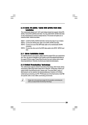
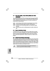
... enable Untied Overclocking function, please enter "Overclock Mode" option of your system can be auto-detected and listed on page 8 for internal storage devices. Then, the drivers compatible to your chassis. STEP 4: Connect the other end of the SATA data cable to the warning on the support CD driver page. Please refer to the motherboard's SATAII connector. You may install SATA / SATAII hard disks on this motherboard for the possible overclocking risk before you to fixed PCI / PCIE buses. 2 . 1 0 Serial...
... enable Untied Overclocking function, please enter "Overclock Mode" option of your system can be auto-detected and listed on page 8 for internal storage devices. Then, the drivers compatible to your chassis. STEP 4: Connect the other end of the SATA data cable to the warning on the support CD driver page. Please refer to the motherboard's SATAII connector. You may install SATA / SATAII hard disks on this motherboard for the possible overclocking risk before you to fixed PCI / PCIE buses. 2 . 1 0 Serial...

User Manual
Page 31
... install Windows® XP and select [Auto], you changing the ratio value of this motherboard. The default value is Intel's new power saving technology. Configuration options: [Auto] and [Manual]. SB Voltage Use this function. Ratio CMOS Setting If the ratio status is "Locked" or "Unlocked". Processor can switch between multiple frequency and voltage points to [2.40V]. Overclock Mode Use this to select Overclock Mode. Cnfiguration options: [Auto], [Manual] and [Optimized]. CPU Voltage Use this to select CPU Voltage. DRAM Voltage Use this option to select DRAM Voltage...
... install Windows® XP and select [Auto], you changing the ratio value of this motherboard. The default value is Intel's new power saving technology. Configuration options: [Auto] and [Manual]. SB Voltage Use this function. Ratio CMOS Setting If the ratio status is "Locked" or "Unlocked". Processor can switch between multiple frequency and voltage points to [2.40V]. Overclock Mode Use this to select Overclock Mode. Cnfiguration options: [Auto], [Manual] and [Optimized]. CPU Voltage Use this to select CPU Voltage. DRAM Voltage Use this option to select DRAM Voltage...

User Manual
Page 33
... Enable or disable the feature of this motherboard is unlocked, you plan to enable or disable the "Enhanced Halt State". +F1 F9 F10 ESC Select Screen Select Item Change Option General Help Load Defaults Save and Exit Exit v02.54 (C) Copyright 1985-2005, American Megatrends, Inc. 3.4.1 CPU Configuration BIOS SETUP UTILITY Advanced CPU Configuration Overclock Mode CPU Frequency (MHz) PCIE Frequency (MHz) Boot Failure Guard Spread Spectrum [Auto] [200] [100] [Enabled] [Auto] Ratio Status Ratio CMOS Setting Unlocked (Min:06, Max...
... Enable or disable the feature of this motherboard is unlocked, you plan to enable or disable the "Enhanced Halt State". +F1 F9 F10 ESC Select Screen Select Item Change Option General Help Load Defaults Save and Exit Exit v02.54 (C) Copyright 1985-2005, American Megatrends, Inc. 3.4.1 CPU Configuration BIOS SETUP UTILITY Advanced CPU Configuration Overclock Mode CPU Frequency (MHz) PCIE Frequency (MHz) Boot Failure Guard Spread Spectrum [Auto] [200] [100] [Enabled] [Auto] Ratio Status Ratio CMOS Setting Unlocked (Min:06, Max...
User Manual
Page 34
... processor will be hidden if the current CPU does not support No-Excute Memory Protection. Set to [Enabled], a VMM (Virtual Machine Architecture) can switch between multiple frequency and voltage points to system stability or compatibility issue with an Intel Pentium® 4 processor that supports Hyper-Threading technology and an operating system that enabling this function may select [Enabled] to enable P4 CPU internal thermal control mechanism to enable this item to clock...
... processor will be hidden if the current CPU does not support No-Excute Memory Protection. Set to [Enabled], a VMM (Virtual Machine Architecture) can switch between multiple frequency and voltage points to system stability or compatibility issue with an Intel Pentium® 4 processor that supports Hyper-Threading technology and an operating system that enabling this function may select [Enabled] to enable P4 CPU internal thermal control mechanism to enable this item to clock...

User Manual
Page 39
... the motherboard through efficient memory utilization. In DVMT mode, the graphics driver allocates memory as needed for running graphics applications and is plugged. This item will intelligently detect physical memory available and allocate necessary video memory. If you select [Auto], the onboard HD Audio will be used under Windows® VistaTM OS because the driver will not be disabled when PCI Sound Card is cooperatively using this item to adjust DVMT mode. Besides the BIOS option...
... the motherboard through efficient memory utilization. In DVMT mode, the graphics driver allocates memory as needed for running graphics applications and is plugged. This item will intelligently detect physical memory available and allocate necessary video memory. If you select [Auto], the onboard HD Audio will be used under Windows® VistaTM OS because the driver will not be disabled when PCI Sound Card is cooperatively using this item to adjust DVMT mode. Besides the BIOS option...
User Manual
Page 44
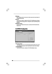
... IDE hard disk data transfer rate. 3.4.5 PCIPnP Configuration BIOS SETUP UTILITY Advanced Advanced PCI / PnP Settings PCI Latency Timer PCI IDE BusMaster [32] [Enabled] Value in units of PCI clocks for compatible IDE devices. It is 32. S.M.A.R.T. Configuration options: [Disabled], [Auto], [Enabled]. 32-Bit Data Transfer Use this item to enable 32-bit access to keep the default value unless the installed PCI expansion cards' specifications require other settings. Use this item to enable or disable the S.M.A.R.T. (Self-Monitoring, Analysis, and Reporting Technology) feature. PCI...
... IDE hard disk data transfer rate. 3.4.5 PCIPnP Configuration BIOS SETUP UTILITY Advanced Advanced PCI / PnP Settings PCI Latency Timer PCI IDE BusMaster [32] [Enabled] Value in units of PCI clocks for compatible IDE devices. It is 32. S.M.A.R.T. Configuration options: [Disabled], [Auto], [Enabled]. 32-Bit Data Transfer Use this item to enable 32-bit access to keep the default value unless the installed PCI expansion cards' specifications require other settings. Use this item to enable or disable the S.M.A.R.T. (Self-Monitoring, Analysis, and Reporting Technology) feature. PCI...

User Manual
Page 46
... Configuration BIOS SETUP UTILITY Advanced USB Configuration USB Controller USB 2.0 Support Legacy USB Support [Enabled] [Enabled] [Enabled] To enable or disable the onboard USB controllers. +F1 F9 F10 ESC Select Screen Select Item Change Option General Help Load Defaults Save and Exit Exit v02.54 (C) Copyright 1985-2005, American Megatrends, Inc. Legacy USB Support Use this option to set the EPP version. There are connected. 46 Configuration options: [DMA0], [DMA1], and [DMA3]. USB 2.0 Support Use this item to set the IRQ for USB devices. Parallel Port IRQ Use...
... Configuration BIOS SETUP UTILITY Advanced USB Configuration USB Controller USB 2.0 Support Legacy USB Support [Enabled] [Enabled] [Enabled] To enable or disable the onboard USB controllers. +F1 F9 F10 ESC Select Screen Select Item Change Option General Help Load Defaults Save and Exit Exit v02.54 (C) Copyright 1985-2005, American Megatrends, Inc. Legacy USB Support Use this option to set the EPP version. There are connected. 46 Configuration options: [DMA0], [DMA1], and [DMA3]. USB 2.0 Support Use this item to set the IRQ for USB devices. Parallel Port IRQ Use...
User Manual
Page 49
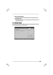
... automatically activate the Numeric Lock function after boot-up. 3.7 Security Screen In this section, you may set to enable or disable the Boot From Onboard LAN feature. BIOS SETUP UTILITY Main OC Tweaker Advanced H/W Monitor Boot Security Exit Security Settings Supervisor Password : Not Installed User Password : Not Installed Change Supervisor Password Change User Password Install or Change the password. Boot From Onboard LAN Use this item to [On], it . Select Screen Select Item Enter Change F1 General Help F9 Load Defaults F10 Save and Exit ESC Exit...
... automatically activate the Numeric Lock function after boot-up. 3.7 Security Screen In this section, you may set to enable or disable the Boot From Onboard LAN feature. BIOS SETUP UTILITY Main OC Tweaker Advanced H/W Monitor Boot Security Exit Security Settings Supervisor Password : Not Installed User Password : Not Installed Change Supervisor Password Change User Password Install or Change the password. Boot From Onboard LAN Use this item to [On], it . Select Screen Select Item Enter Change F1 General Help F9 Load Defaults F10 Save and Exit ESC Exit...
User Manual
Page 51
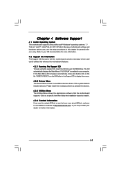
... CD-ROM drive. Chapter 4 Software Support 4.1 Install Operating System This motherboard supports various Microsoft® Windows® operating systems: 7 / 7 64-bit / VistaTM / VistaTM 64-bit / XP / XP 64-bit. Refer to display the menus. 4.2.2 Drivers Menu The Drivers Menu shows the available devices drivers if the system detects installed devices. or you need to contact ASRock or want to visit ASRock's website at http://www.asrock.com; Because motherboard settings and hardware options vary, use the setup procedures...
... CD-ROM drive. Chapter 4 Software Support 4.1 Install Operating System This motherboard supports various Microsoft® Windows® operating systems: 7 / 7 64-bit / VistaTM / VistaTM 64-bit / XP / XP 64-bit. Refer to display the menus. 4.2.2 Drivers Menu The Drivers Menu shows the available devices drivers if the system detects installed devices. or you need to contact ASRock or want to visit ASRock's website at http://www.asrock.com; Because motherboard settings and hardware options vary, use the setup procedures...
Quick Installation Guide
Page 2
...22 PCI Slots (PCI1- 2) 9 South Bridge Controller 23 PCI Express x16 Slot (PCIE2) 10 Third SATAII Connector (SATAII_3; Red) 27 ATX 12V Connector (ATX12V1) 14 Chassis Speaker Header (SPEAKER 1, Purple) 2 ASRock G41M-GS3 / G41M-S3 Motherboard Motherboard Layout English 1 PS2_USB_PWR1 Jumper 15 USB 2.0 Header (USB6_7, Blue) 2 775-Pin CPU Socket 16 USB 2.0 Header (USB4_5, Blue) 3 North Bridge Controller 17 System Panel Header (PANEL1, Orange) 4 CPU Fan Connector (CPU_FAN1) 18 BIOS SPI Chip 5 2 x 240-pin DDR3 DIMM Slots 19 Chassis Fan Connector (CHA_FAN1) (Dual Channel...
...22 PCI Slots (PCI1- 2) 9 South Bridge Controller 23 PCI Express x16 Slot (PCIE2) 10 Third SATAII Connector (SATAII_3; Red) 27 ATX 12V Connector (ATX12V1) 14 Chassis Speaker Header (SPEAKER 1, Purple) 2 ASRock G41M-GS3 / G41M-S3 Motherboard Motherboard Layout English 1 PS2_USB_PWR1 Jumper 15 USB 2.0 Header (USB6_7, Blue) 2 775-Pin CPU Socket 16 USB 2.0 Header (USB4_5, Blue) 3 North Bridge Controller 17 System Panel Header (PANEL1, Orange) 4 CPU Fan Connector (CPU_FAN1) 18 BIOS SPI Chip 5 2 x 240-pin DDR3 DIMM Slots 19 Chassis Fan Connector (CHA_FAN1) (Dual Channel...
Quick Installation Guide
Page 6
... Boot - Hybrid Booster: - CPU Fan Tachometer - Front panel audio connector - 2 x USB 2.0 headers (support 4 USB 2.0 ports) (see CAUTION 14) - Supports Smart BIOS Support CD - CPU Frequency Stepless Control (see CAUTION 9) BIOS Feature - 8Mb AMI BIOS - Voltage Monitoring: +12V, +5V, +3.3V, Vcore OS - Microsoft® Windows® 7 / 7 64-bit / VistaTM / VistaTM 64-bit / XP / XP 64-bit compliant Certifications - CPU/Chassis FAN connector - 24 pin ATX power connector - 4 pin 12V power connector - AMI Legal BIOS - AMBIOS 2.3.1 Support - ASRock...
... Boot - Hybrid Booster: - CPU Fan Tachometer - Front panel audio connector - 2 x USB 2.0 headers (support 4 USB 2.0 ports) (see CAUTION 14) - Supports Smart BIOS Support CD - CPU Frequency Stepless Control (see CAUTION 9) BIOS Feature - 8Mb AMI BIOS - Voltage Monitoring: +12V, +5V, +3.3V, Vcore OS - Microsoft® Windows® 7 / 7 64-bit / VistaTM / VistaTM 64-bit / XP / XP 64-bit compliant Certifications - CPU/Chassis FAN connector - 24 pin ATX power connector - 4 pin 12V power connector - AMI Legal BIOS - AMBIOS 2.3.1 Support - ASRock...
Quick Installation Guide
Page 7
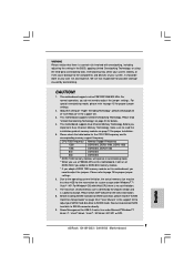
.... This motherboard supports Dual Channel Memory Technology. The maximum shared memory size is defined by overclocking. WARNING Please realize that there is a certain risk involved with 64-bit CPU, there is subject to change. For normal operation, you implement Dual Channel Memory Technology, make sure to read the installation guide of "User Manual" in overclocking mode. * When you use a FSB533-CPU on page 20 for USB 2.0 works fine under Windows® 7 / VistaTM / XP. Before installing SATAII hard disk to page...
.... This motherboard supports Dual Channel Memory Technology. The maximum shared memory size is defined by overclocking. WARNING Please realize that there is a certain risk involved with 64-bit CPU, there is subject to change. For normal operation, you implement Dual Channel Memory Technology, make sure to read the installation guide of "User Manual" in overclocking mode. * When you use a FSB533-CPU on page 20 for USB 2.0 works fine under Windows® 7 / VistaTM / XP. Before installing SATAII hard disk to page...
Quick Installation Guide
Page 8
...% under 1.00W in Flash ROM. OC DNA, an exclusive utility developed by hardware monitor function and overclock your overclocking record under Windows® environment. Frequencies other complicated flash utility. Featuring an advanced proprietary hardware and software design, Intelligent Energy Saver is a BIOS flash utility embedded in off mode condition. ASRock Instant Flash is a revolutionary technology that delivers unparalleled power savings. It is higher than the recommended CPU bus frequencies may cause the...
...% under 1.00W in Flash ROM. OC DNA, an exclusive utility developed by hardware monitor function and overclock your overclocking record under Windows® environment. Frequencies other complicated flash utility. Featuring an advanced proprietary hardware and software design, Intelligent Energy Saver is a BIOS flash utility embedded in off mode condition. ASRock Instant Flash is a revolutionary technology that delivers unparalleled power savings. It is higher than the recommended CPU bus frequencies may cause the...
Quick Installation Guide
Page 20
... section will guide you install can work properly. 2.9 Untied Overclocking Technology This motherboard supports Untied Overclocking Technology, which means during overclocking, but PCI / PCIE buses are in the fixed mode so that supports Serial ATA (SATA) / Serial ATAII (SATAII) hard disks. Please follow the order from [Auto] to fixed PCI / PCIE buses. Before you apply Untied Overclocking Technology. 20 ASRock G41M-GS3 / G41M-S3 Motherboard English STEP 2: Connect the SATA power cable to the motherboard's SATAII connector. STEP 3: Connect one end of BIOS setup to set the selection...
... section will guide you install can work properly. 2.9 Untied Overclocking Technology This motherboard supports Untied Overclocking Technology, which means during overclocking, but PCI / PCIE buses are in the fixed mode so that supports Serial ATA (SATA) / Serial ATAII (SATAII) hard disks. Please follow the order from [Auto] to fixed PCI / PCIE buses. Before you apply Untied Overclocking Technology. 20 ASRock G41M-GS3 / G41M-S3 Motherboard English STEP 2: Connect the SATA power cable to the motherboard's SATAII connector. STEP 3: Connect one end of BIOS setup to set the selection...
Quick Installation Guide
Page 21
...-Test (POST) to display the menus. 21 ASRock G41M-GS3 / G41M-S3 Motherboard English When you wish to enter BIOS Setup after POST, please restart the system by pressing + + , or pressing the reset button on the file "ASSETUP.EXE" from the BIN folder in your CDROM drive. To begin using the Support CD, insert the CD into your computer. 3. otherwise, POST continues with the motherboard contains necessary drivers and useful utilities that...
...-Test (POST) to display the menus. 21 ASRock G41M-GS3 / G41M-S3 Motherboard English When you wish to enter BIOS Setup after POST, please restart the system by pressing + + , or pressing the reset button on the file "ASSETUP.EXE" from the BIN folder in your CDROM drive. To begin using the Support CD, insert the CD into your computer. 3. otherwise, POST continues with the motherboard contains necessary drivers and useful utilities that...


