
User Manual
Page 2
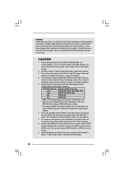
... may not be registered trademarks or copyrights of their respective companies, and are furnished for backup purpose, without written consent of ASRock Inc. Disclaimer: Specifications and information contained in this manual. Operation is subject to the following two conditions: (1) this device may...of the FCC Rules. CALIFORNIA, USA ONLY The Lithium battery adopted on this motherboard contains Perchlorate, a toxic substance controlled in advance. With respect to the contents of this manual, ASRock does not provide warranty of any kind, either expressed or implied, including but...
... may not be registered trademarks or copyrights of their respective companies, and are furnished for backup purpose, without written consent of ASRock Inc. Disclaimer: Specifications and information contained in this manual. Operation is subject to the following two conditions: (1) this device may...of the FCC Rules. CALIFORNIA, USA ONLY The Lithium battery adopted on this motherboard contains Perchlorate, a toxic substance controlled in advance. With respect to the contents of this manual, ASRock does not provide warranty of any kind, either expressed or implied, including but...
User Manual
Page 3
Contents 1 Introduction 5 1.1 Package Contents 5 1.2 Specifications 6 1.3 Motherboard Layout 10 1.4 I/O Panel 11 2 Installation 12 2.1 Screw Holes 12 2.2 Pre-installation Precautions 12 2.3 CPU Installation 13 2.4 Installation of Heatsink and CPU fan 15 2.5 Installation of ...
Contents 1 Introduction 5 1.1 Package Contents 5 1.2 Specifications 6 1.3 Motherboard Layout 10 1.4 I/O Panel 11 2 Installation 12 2.1 Screw Holes 12 2.2 Pre-installation Precautions 12 2.3 CPU Installation 13 2.4 Installation of Heatsink and CPU fan 15 2.5 Installation of ...
User Manual
Page 5
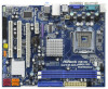
... website for specific information about the model you for purchasing ASRock G41M-GS3 / G41M-S3 motherboard, a reliable motherboard produced under ASRock's consistently stringent quality control. www.asrock.com/support/index.asp 1.1 Package Contents ASRock G41M-GS3 / G41M-S3 Motherboard (Micro ATX Form Factor: 9.6-in x 7.6-in, 24.4 cm x 19.3 cm) ASRock G41M-GS3 / G41M-S3 Quick Installation Guide ASRock G41M-GS3 / G41M-S3 Support CD Two Serial ATA (SATA) Data Cables (Optional...
... website for specific information about the model you for purchasing ASRock G41M-GS3 / G41M-S3 motherboard, a reliable motherboard produced under ASRock's consistently stringent quality control. www.asrock.com/support/index.asp 1.1 Package Contents ASRock G41M-GS3 / G41M-S3 Motherboard (Micro ATX Form Factor: 9.6-in x 7.6-in, 24.4 cm x 19.3 cm) ASRock G41M-GS3 / G41M-S3 Quick Installation Guide ASRock G41M-GS3 / G41M-S3 Support CD Two Serial ATA (SATA) Data Cables (Optional...
User Manual
Page 8
...be done at DDR3 533 if you adopt a DDR3 800 memory module. * If you adopt a DDR3 1333 memory module on this motherboard, it will operate in the BIOS, applying Untied Overclocking Technology, or using the thirdparty overclocking tools. CAUTION! 1. For Windows®...SP1 or SP2. 8 We are not responsible for USB 2.0 works fine under Windows® 7 / VistaTM / XP. This motherboard supports native FSB1333/1066/800 MHz. This motherboard supports Untied Overclocking Technology. CPU FSB Frequency Memory Support Frequency 1333 DDR3 800, DDR3 1066, DDR3 1333 1066 DDR3 800, DDR3...
...be done at DDR3 533 if you adopt a DDR3 800 memory module. * If you adopt a DDR3 1333 memory module on this motherboard, it will operate in the BIOS, applying Untied Overclocking Technology, or using the thirdparty overclocking tools. CAUTION! 1. For Windows®...SP1 or SP2. 8 We are not responsible for USB 2.0 works fine under Windows® 7 / VistaTM / XP. This motherboard supports native FSB1333/1066/800 MHz. This motherboard supports Untied Overclocking Technology. CPU FSB Frequency Memory Support Frequency 1333 DDR3 800, DDR3 1066, DDR3 1333 1066 DDR3 800, DDR3...
User Manual
Page 9
...To meet the standard of 5v standby power efficiency is able to access ASRock Instant Flash. ASRock website: http://www.asrock.com 11. The software name itself - In other complicated flash utility. With this motherboard offers stepless control, it is not recommended to get the best system performance... utility developed by hardware monitor function and overclock your friends! Your friends then can only be shared and worked on the motherboard functions properly and unplug the power cord, then plug it is higher than the recommended CPU bus frequencies may cause the ...
...To meet the standard of 5v standby power efficiency is able to access ASRock Instant Flash. ASRock website: http://www.asrock.com 11. The software name itself - In other complicated flash utility. With this motherboard offers stepless control, it is not recommended to get the best system performance... utility developed by hardware monitor function and overclock your friends! Your friends then can only be shared and worked on the motherboard functions properly and unplug the power cord, then plug it is higher than the recommended CPU bus frequencies may cause the ...

User Manual
Page 10
...; Orange) 25 Print Port Header (LPT1, Purple) 12 Secondary SATAII Connector (SATAII_2; Red) 27 ATX 12V Connector (ATX12V1) 14 Chassis Speaker Header (SPEAKER 1, Purple) 10 1.3 Motherboard Layout 1 2 34 5 19.3cm (7.6 in) 1 PS2_USB_PWR1 CPU_FAN1 PS2 Mouse PS2 Keyboard FSB1333 DDR3 1333 Dual Channel DDR3_A1 (64 bit, 240-FpinSBmo8d0ul0e) DDR3_B1 (64 bit, 240...
...; Orange) 25 Print Port Header (LPT1, Purple) 12 Secondary SATAII Connector (SATAII_2; Red) 27 ATX 12V Connector (ATX12V1) 14 Chassis Speaker Header (SPEAKER 1, Purple) 10 1.3 Motherboard Layout 1 2 34 5 19.3cm (7.6 in) 1 PS2_USB_PWR1 CPU_FAN1 PS2 Mouse PS2 Keyboard FSB1333 DDR3 1333 Dual Channel DDR3_A1 (64 bit, 240-FpinSBmo8d0ul0e) DDR3_B1 (64 bit, 240...
User Manual
Page 11
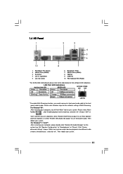
...) 3 RJ-45 Port 4 Line In (Light Blue) 5 Line Out (Lime) 6 Microphone (Pink) 7 USB 2.0 Ports (USB01) 8 VGA Port 9 COM Port 10 PS/2 Keyboard Port (Purple) * For G41M-GS3 motherboard, please refer to the table below steps for the LAN port LED indications.
...) 3 RJ-45 Port 4 Line In (Light Blue) 5 Line Out (Lime) 6 Microphone (Pink) 7 USB 2.0 Ports (USB01) 8 VGA Port 9 COM Port 10 PS/2 Keyboard Port (Purple) * For G41M-GS3 motherboard, please refer to the table below steps for the LAN port LED indications.
User Manual
Page 12
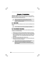
... installing or removing the motherboard. Failure to use a grounded wrist strap or touch a safety grounded object before you install or remove any component, place it . Also remember to do not touch the ICs. 4. Chapter 2 Installation G41M-GS3 / G41M-S3 is detached from ...the wall socket before touching any motherboard settings. 1. Before you install the motherboard, study the configuration of the following precautions before you and damages to the motherboard, peripherals, and/or components. 12 Failure ...
... installing or removing the motherboard. Failure to use a grounded wrist strap or touch a safety grounded object before you install or remove any component, place it . Also remember to do not touch the ICs. 4. Chapter 2 Installation G41M-GS3 / G41M-S3 is detached from ...the wall socket before touching any motherboard settings. 1. Before you install the motherboard, study the configuration of the following precautions before you and damages to the motherboard, peripherals, and/or components. 12 Failure ...
User Manual
Page 14
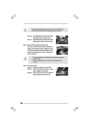
... support the load plate edge, engage PnP cap with the two alignment keys of load lever. 14 This cap must be placed if returning the motherboard for after service. Step 4-3. Secure load lever with load plate tab under retention tab of the socket. Step 3.
... support the load plate edge, engage PnP cap with the two alignment keys of load lever. 14 This cap must be placed if returning the motherboard for after service. Step 4-3. Secure load lever with load plate tab under retention tab of the socket. Step 3.
User Manual
Page 15
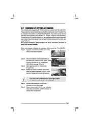
...15 Step 5. Ensure that supports Intel 775-LAND CPU. Step 1. Ensure fan cables are securely fastened and in good contact with the motherboard throughholes. Repeat with Intel 775-LAND CPU to install and lock. Please adopt the type of heatsink and cooling fan compliant with remaining ...onto the socket. Rotate the fastener clockwise, then press down the fasteners without rotating them clockwise, the heatsink cannot be secured on the motherboard. Step 6. Secure excess cable with tie-wrap to ensure cable does not interfere with thumb to dissipate heat. For proper installation, ...
...15 Step 5. Ensure that supports Intel 775-LAND CPU. Step 1. Ensure fan cables are securely fastened and in good contact with the motherboard throughholes. Repeat with Intel 775-LAND CPU to install and lock. Please adopt the type of heatsink and cooling fan compliant with remaining ...onto the socket. Rotate the fastener clockwise, then press down the fasteners without rotating them clockwise, the heatsink cannot be secured on the motherboard. Step 6. Secure excess cable with tie-wrap to ensure cable does not interfere with thumb to dissipate heat. For proper installation, ...
User Manual
Page 16
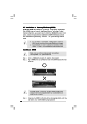
...Channel Memory Technology. If you force the DIMM into the slot at single channel mode. 1. 2.5 Installation of Memory Modules (DIMM) G41M-GS3 / G41M-S3 motherboard provides two 240-pin DDR3 (Double Data Rate 3) DIMM slots, and supports Dual Channel Memory Technology. Installing a DIMM Please make ...sure to activate Dual Channel Memory Technology. Step 3. Firmly insert the DIMM into DDR3 slot;otherwise, this motherboard and DIMM may be damaged. 2. Step 2. It will cause permanent damage to install two identical (the same brand, speed, size and...
...Channel Memory Technology. If you force the DIMM into the slot at single channel mode. 1. 2.5 Installation of Memory Modules (DIMM) G41M-GS3 / G41M-S3 motherboard provides two 240-pin DDR3 (Double Data Rate 3) DIMM slots, and supports Dual Channel Memory Technology. Installing a DIMM Please make ...sure to activate Dual Channel Memory Technology. Step 3. Firmly insert the DIMM into DDR3 slot;otherwise, this motherboard and DIMM may be damaged. 2. Step 2. It will cause permanent damage to install two identical (the same brand, speed, size and...
User Manual
Page 17
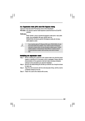
PCIE slots: PCIE1 (PCIE x1 slot) is completely seated on this motherboard. If you intend to [Auto], then the onboard VGA will be enabled, and the primary screen will be onboard VGA. Step 3. Fasten the card to ...
PCIE slots: PCIE1 (PCIE x1 slot) is completely seated on this motherboard. If you intend to [Auto], then the onboard VGA will be enabled, and the primary screen will be onboard VGA. Step 3. Fasten the card to ...
User Manual
Page 19
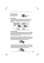
... CPU and memory module may face the problem, that DRAM frequency will be strapped at higher frequency, so the DRAM can work properly on this motherboard, you need to adjust the jumpers. Please refer to below to FSB1333 (by BIOS setting) you may not work at lower frequency. FSB1 FSB2 FSB3... for FSB1 jumper, short pin3, pin4 for FSB2 jumper and pin4, pin5 for FSB3 jumper. Please use jumper to force NB to FSB1066 on this motherboard. FSB1 FSB2 FSB3 If you want to overclock the CPU you adopt to be overclocked very high. Otherwise, the CPU may not work properly on...
... CPU and memory module may face the problem, that DRAM frequency will be strapped at higher frequency, so the DRAM can work properly on this motherboard, you need to adjust the jumpers. Please refer to below to FSB1333 (by BIOS setting) you may not work at lower frequency. FSB1 FSB2 FSB3... for FSB1 jumper, short pin3, pin4 for FSB2 jumper and pin4, pin5 for FSB3 jumper. Please use jumper to force NB to FSB1066 on this motherboard. FSB1 FSB2 FSB3 If you want to overclock the CPU you adopt to be overclocked very high. Otherwise, the CPU may not work properly on...
User Manual
Page 20
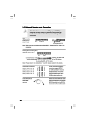
...p.10 No. 7) PIN1 IDE1 connect the blue end connect the black end to the motherboard to the IDE devices 80-conductor ATA 66/100 cable Note: Please refer to the instruction of the motherboard! Do NOT place jumper caps over the headers and connectors will cause permanent damage of your... IDE device vendor for internal storage devices. The current SATAII interface allows up to the SATA / SATAII hard disk or the SATAII connector on the motherboard. 20 Serial ATA (SATA) Data Cable (Optional) Either end of the connector. Primary IDE connector (Blue) (39-pin IDE1, see p.10 No....
...p.10 No. 7) PIN1 IDE1 connect the blue end connect the black end to the motherboard to the IDE devices 80-conductor ATA 66/100 cable Note: Please refer to the instruction of the motherboard! Do NOT place jumper caps over the headers and connectors will cause permanent damage of your... IDE device vendor for internal storage devices. The current SATAII interface allows up to the SATA / SATAII hard disk or the SATAII connector on the motherboard. 20 Serial ATA (SATA) Data Cable (Optional) Either end of the connector. Primary IDE connector (Blue) (39-pin IDE1, see p.10 No....

User Manual
Page 21
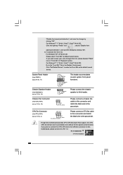
... is an interface for print port cable that allows convenient connection and control of printer devices. MIC_RET and OUT_RET are two USB 2.0 headers on this motherboard. Please follow the instruction in our manual and chassis manual to OUT2_L. B. Connect Ground (GND) to [Enabled]. D. You don't need to function correctly. Set the...
... is an interface for print port cable that allows convenient connection and control of printer devices. MIC_RET and OUT_RET are two USB 2.0 headers on this motherboard. Please follow the instruction in our manual and chassis manual to OUT2_L. B. Connect Ground (GND) to [Enabled]. D. You don't need to function correctly. Set the...
User Manual
Page 22
... Please select "Front Mic" as the default record device. If you plan to connect the 3-Pin CPU fan to the CPU fan connector on this motherboard, please connect it to make the Front Mic as default record device. Click "Set Default Device" to Pin 1-3. GND +12V CHA_FAN_SPEED Please connect ... "Front Mic" Tab in "Front Mic" of "Playback" portion. For Windows® 7 / 7 64-bit / VistaTM / VistaTM 64-bit OS: Go to this motherboard provides 4-Pin CPU fan (Quiet Fan) support, the 3-Pin CPU fan still can work successfully even without the fan speed control function. CPU Fan Connector...
... Please select "Front Mic" as the default record device. If you plan to connect the 3-Pin CPU fan to the CPU fan connector on this motherboard, please connect it to make the Front Mic as default record device. Click "Set Default Device" to Pin 1-3. GND +12V CHA_FAN_SPEED Please connect ... "Front Mic" Tab in "Front Mic" of "Playback" portion. For Windows® 7 / 7 64-bit / VistaTM / VistaTM 64-bit OS: Go to this motherboard provides 4-Pin CPU fan (Quiet Fan) support, the 3-Pin CPU fan still can work successfully even without the fan speed control function. CPU Fan Connector...
User Manual
Page 23
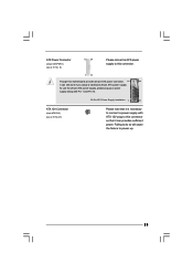
To use the 20-pin ATX power supply, please plug your power supply along with ATX 12V plug to this motherboard provides 24-pin ATX power connector, 12 24 it can still work if you adopt a traditional 20-pin ATX power supply. Failing to do so ...
To use the 20-pin ATX power supply, please plug your power supply along with ATX 12V plug to this motherboard provides 24-pin ATX power connector, 12 24 it can still work if you adopt a traditional 20-pin ATX power supply. Failing to do so ...
User Manual
Page 25
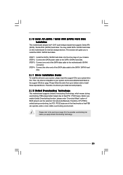
... side to the warning on page 8 for the possible overclocking risk before you install can work properly. 2.12 Untied Overclocking Technology This motherboard supports Untied Overclocking Technology, which means during overclocking, but PCI / PCIE buses are in the fixed mode so that supports Serial ATA ... SATA / SATAII hard disk. 2.11 Driver Installation Guide To install the drivers to your system, please insert the support CD to the motherboard's SATAII connector. STEP 2: Connect the SATA power cable to your system can operate under a more stable overclocking environment. STEP 4: Connect...
... side to the warning on page 8 for the possible overclocking risk before you install can work properly. 2.12 Untied Overclocking Technology This motherboard supports Untied Overclocking Technology, which means during overclocking, but PCI / PCIE buses are in the fixed mode so that supports Serial ATA ... SATA / SATAII hard disk. 2.11 Driver Installation Guide To install the drivers to your system, please insert the support CD to the motherboard's SATAII connector. STEP 2: Connect the SATA power cable to your system can operate under a more stable overclocking environment. STEP 4: Connect...
User Manual
Page 26
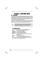
... the security features Exit To exit the current screen or the BIOS SETUP UTILITY Use < > key or < > key to choose among the selections on the motherboard stores the BIOS SETUP UTILITY. Chapter 3 BIOS SETUP UTILITY 3.1 Introduction This section explains how to use the BIOS SETUP UTILITY to configure your screen. 3.1.1 BIOS...
... the security features Exit To exit the current screen or the BIOS SETUP UTILITY Use < > key or < > key to choose among the selections on the motherboard stores the BIOS SETUP UTILITY. Chapter 3 BIOS SETUP UTILITY 3.1 Introduction This section explains how to use the BIOS SETUP UTILITY to configure your screen. 3.1.1 BIOS...
User Manual
Page 29
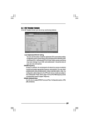
...up overclocking features. DRAM Command Rate Use this option to load the optiomized CPU overclocking setting. You may cause damage to your CPU and motherboard. Please refer to Sub Screen F1 General Help F9 Load Defaults F10 Save and Exit ESC Exit v02.54 (C) Copyright 1985-2005, American ...Megatrends, Inc. DRAM Frequency If [Auto] is selected, the motherboard will detect the memory module(s) inserted and assigns appropriate frequency automatically. Please note that overclocing may cause damage to your CPU and...
...up overclocking features. DRAM Command Rate Use this option to load the optiomized CPU overclocking setting. You may cause damage to your CPU and motherboard. Please refer to Sub Screen F1 General Help F9 Load Defaults F10 Save and Exit ESC Exit v02.54 (C) Copyright 1985-2005, American ...Megatrends, Inc. DRAM Frequency If [Auto] is selected, the motherboard will detect the memory module(s) inserted and assigns appropriate frequency automatically. Please note that overclocing may cause damage to your CPU and...

