RAID Installation Guide
Page 6
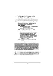
... supported under Windows® XP / XP 64-bit. Enter BIOS SETUP UTILITY Advanced screen Storage Configuration. If you want to use both "RAID Installation Guide" and "Intel Rapid Storage Information" for proper configuration. 2.3 Installing Windows® 7 / 7 64-bit / VistaTM / VistaTM 64-bit With RAID Functions RAID mode is located in the folder at the following path: .. \ RAID Installation Guide STEP 3: Install Windows® 7 / 7 64-bit / VistaTM / VistaTM 64-bit OS on your SATA / SATA2 / SATA3 HDDs with RAID...
... supported under Windows® XP / XP 64-bit. Enter BIOS SETUP UTILITY Advanced screen Storage Configuration. If you want to use both "RAID Installation Guide" and "Intel Rapid Storage Information" for proper configuration. 2.3 Installing Windows® 7 / 7 64-bit / VistaTM / VistaTM 64-bit With RAID Functions RAID mode is located in the folder at the following path: .. \ RAID Installation Guide STEP 3: Install Windows® 7 / 7 64-bit / VistaTM / VistaTM 64-bit OS on your SATA / SATA2 / SATA3 HDDs with RAID...
Intel Rapid Storage Guide
Page 13
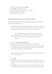
... necessary files. 4. Select your controller from the list of Windows XP* setup (during operating system setup: 1. Use the up and down arrow keys to create a floppy disk with a screen asking you see a message in the status line that says, Please insert the disk labeled Manufacturer-supplied hardware support disk into Drive A:, insert ;a floppy disk containing the following steps to load support for mass storage device(s). 2. Press Enter to confirm your controller and continue. Install the RAID Driver Using...
... necessary files. 4. Select your controller from the list of Windows XP* setup (during operating system setup: 1. Use the up and down arrow keys to create a floppy disk with a screen asking you see a message in the status line that says, Please insert the disk labeled Manufacturer-supplied hardware support disk into Drive A:, insert ;a floppy disk containing the following steps to load support for mass storage device(s). 2. Press Enter to confirm your controller and continue. Install the RAID Driver Using...

Quick Installation Guide
Page 4
... (PSC) 36 COM Port Header (COM1) 11 ATX Power Connector (ATXPWR1) 37 Infrared Module Header (IR1) 12 Chassis Fan Connector (CHA_FAN3) 38 SLI / XFIRE Power Connector 13 USB 3.0 Header (USB3_11_12, Black) 39 HDMI_SPDIF Header 14 USB 3.0 Header (USB3_9_10, Black) (HDMI_SPDIF1, Black) 15 Intel X79 Chipset 40 Front Panel Audio Header 16 SPI Flash Memory (64Mb) (HD_AUDIO1, Black) 17 SATA2 Connector (SATA2_0_1, Black) 41 PCI Express 3.0 x16 Slot (PCIE7, Red) 18 SATA2 Connector (SATA2_2_3, Black) 42 PCI Express 2.0 x1 Slot (PCIE6, Black) 19...
... (PSC) 36 COM Port Header (COM1) 11 ATX Power Connector (ATXPWR1) 37 Infrared Module Header (IR1) 12 Chassis Fan Connector (CHA_FAN3) 38 SLI / XFIRE Power Connector 13 USB 3.0 Header (USB3_11_12, Black) 39 HDMI_SPDIF Header 14 USB 3.0 Header (USB3_9_10, Black) (HDMI_SPDIF1, Black) 15 Intel X79 Chipset 40 Front Panel Audio Header 16 SPI Flash Memory (64Mb) (HD_AUDIO1, Black) 17 SATA2 Connector (SATA2_0_1, Black) 41 PCI Express 3.0 x16 Slot (PCIE7, Red) 18 SATA2 Connector (SATA2_2_3, Black) 42 PCI Express 2.0 x1 Slot (PCIE6, Black) 19...

Quick Installation Guide
Page 6
...the BIOS software might be updated, the content of the motherboard and step-by-step installation guide. Introduction Thank you require technical support related to the "User Manual" in , 30.5 cm x 26.7 cm) Fatal1ty X79 Professional Series Quick Installation Guide Fatal1ty X79 Professional Series Support CD 6 x Serial ATA (SATA) Data Cables (Optional) 2 x Serial ATA (SATA) HDD Power Cables (Optional) 1 x I/O Panel Shield 1 x Front USB 3.0 Panel 4 x HDD Screws 6 x Chassis Screws 1 x Rear USB 3.0 Bracket 2 x ASRock SLI_Bridge Cards 1 x ASRock SLI_Bridge_3S Card 1 x ASRock 3-Way SLI Bridge Card...
...the BIOS software might be updated, the content of the motherboard and step-by-step installation guide. Introduction Thank you require technical support related to the "User Manual" in , 30.5 cm x 26.7 cm) Fatal1ty X79 Professional Series Quick Installation Guide Fatal1ty X79 Professional Series Support CD 6 x Serial ATA (SATA) Data Cables (Optional) 2 x Serial ATA (SATA) HDD Power Cables (Optional) 1 x I/O Panel Shield 1 x Front USB 3.0 Panel 4 x HDD Screws 6 x Chassis Screws 1 x Rear USB 3.0 Bracket 2 x ASRock SLI_Bridge Cards 1 x ASRock SLI_Bridge_3S Card 1 x ASRock 3-Way SLI Bridge Card...

Quick Installation Guide
Page 8
...- CPU/Chassis/Power FAN connectors English 8 Fatal1ty X79 Champion Series Motherboard Supports Wake-On-LAN - Supports Dual LAN with LED - Supports PXE I /O SATA3 USB3.0 Connector - HD Audio Jack: Rear Speaker/Central/Bass/Line in/Front Speaker/Microphone (see CAUTION 7) - 2 x SATA3 6.0 Gb/s connectors by Intel® X79, support RAID (RAID 0, RAID 1, RAID 5, RAID 10 and Intel Rapid Storage 3.0), NCQ, AHCI and "Hot Plug" functions - 4 x SATA3 6.0 Gb/s connectors by Marvell SE9230, support RAID (RAID 0, RAID 1 and RAID10), NCQ, AHCI and "Hot Plug" functions - 8 x Rear USB 3.0 ports...
...- CPU/Chassis/Power FAN connectors English 8 Fatal1ty X79 Champion Series Motherboard Supports Wake-On-LAN - Supports Dual LAN with LED - Supports PXE I /O SATA3 USB3.0 Connector - HD Audio Jack: Rear Speaker/Central/Bass/Line in/Front Speaker/Microphone (see CAUTION 7) - 2 x SATA3 6.0 Gb/s connectors by Intel® X79, support RAID (RAID 0, RAID 1, RAID 5, RAID 10 and Intel Rapid Storage 3.0), NCQ, AHCI and "Hot Plug" functions - 4 x SATA3 6.0 Gb/s connectors by Marvell SE9230, support RAID (RAID 0, RAID 1 and RAID10), NCQ, AHCI and "Hot Plug" functions - 8 x Rear USB 3.0 ports...

Quick Installation Guide
Page 9
ACPI 1.1 Compliance Wake Up Events - F-Stream (see CAUTION 16) - ASRock Crashless BIOS (see CAUTION 9) - Smart Switch BIOS Feature Support CD Unique Feature Hardware Monitor - 24 pin ATX power connector - 8 pin 12V power connector - Hybrid Booster: - CPU Frequency Stepless Control (see CAUTION 8) - 1 x Power Switch with LED - 1 x Reset Switch with LED - 1 x Clear CMOS Switch with LED - 64Mb AMI UEFI Legal BIOS with GUI support - Good Night LED - Front panel audio connector - 3 x USB 2.0 headers (support 6 USB 2.0 ports) - 2 x USB 3.0 header (supports 4 USB 3.0 ...
ACPI 1.1 Compliance Wake Up Events - F-Stream (see CAUTION 16) - ASRock Crashless BIOS (see CAUTION 9) - Smart Switch BIOS Feature Support CD Unique Feature Hardware Monitor - 24 pin ATX power connector - 8 pin 12V power connector - Hybrid Booster: - CPU Frequency Stepless Control (see CAUTION 8) - 1 x Power Switch with LED - 1 x Reset Switch with LED - 1 x Clear CMOS Switch with LED - 64Mb AMI UEFI Legal BIOS with GUI support - Good Night LED - Front panel audio connector - 3 x USB 2.0 headers (support 6 USB 2.0 ports) - 2 x USB 3.0 header (supports 4 USB 3.0 ...
Quick Installation Guide
Page 10
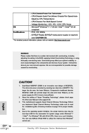
... Fatal1ty X79 Champion Series Motherboard Adjust by stacking two dies into a MOSFET. FCC, CE, WHQL - English CAUTION! 1. Before you implement Quad Channel Memory Technology, make sure to traditional discrete MOSFET, DSM can use ASRock XFast RAM to the operating system limitation, the actual memory size may affect your system's stability, or even cause damage to the components and devices of MOSFETs. - CPU/Chassis Fan Multi-Speed Control - Microsoft® Windows...
... Fatal1ty X79 Champion Series Motherboard Adjust by stacking two dies into a MOSFET. FCC, CE, WHQL - English CAUTION! 1. Before you implement Quad Channel Memory Technology, make sure to traditional discrete MOSFET, DSM can use ASRock XFast RAM to the operating system limitation, the actual memory size may affect your system's stability, or even cause damage to the components and devices of MOSFETs. - CPU/Chassis Fan Multi-Speed Control - Microsoft® Windows...

Quick Installation Guide
Page 11
... load the OC profile in Flash ROM. Currently Intel® Socket 2011 Sandy Bridge-E Processor doesn't support PCIE 3.0, but this motherboard supports 2-channel, 6-channel, and 8-channel modes. With this motherboard supports both stereo and mono modes. Please check Intel's website for you desire a faster, less restricted way of the Fatal1ty Mouse port to 250 Ohm highend headsets, which currently includes Hardware Monitor, Fan Control, Overclocking, OC DNA, Mouse Polling and IES. For audio...
... load the OC profile in Flash ROM. Currently Intel® Socket 2011 Sandy Bridge-E Processor doesn't support PCIE 3.0, but this motherboard supports 2-channel, 6-channel, and 8-channel modes. With this motherboard supports both stereo and mono modes. Please check Intel's website for you desire a faster, less restricted way of the Fatal1ty Mouse port to 250 Ohm highend headsets, which currently includes Hardware Monitor, Fan Control, Overclocking, OC DNA, Mouse Polling and IES. For audio...
Quick Installation Guide
Page 12
..., ASRock Crashless BIOS will automatically finish the BIOS update procedure after regaining power. Administrators are transferring currently. 15. With APP Charger driver installed, you must be used under Windows® OS 32-bit CPU. ASRock website: http://www.asrock.com/Feature/SmartView/index.asp 13. ASRock Crashless BIOS allows users to 12 Fatal1ty X79 Champion Series Motherboard English ASRock website: http://www.asrock.com/Feature/AppCharger/index.asp 12. LAN Application Prioritization: You can configure...
..., ASRock Crashless BIOS will automatically finish the BIOS update procedure after regaining power. Administrators are transferring currently. 15. With APP Charger driver installed, you must be used under Windows® OS 32-bit CPU. ASRock website: http://www.asrock.com/Feature/SmartView/index.asp 13. ASRock Crashless BIOS allows users to 12 Fatal1ty X79 Champion Series Motherboard English ASRock website: http://www.asrock.com/Feature/AppCharger/index.asp 12. LAN Application Prioritization: You can configure...
Quick Installation Guide
Page 35
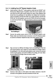
... that both power connectors on the PCI Express graphics card are properly seated on the other graphics cards. Connect the auxiliary power source to PCIE1 slot. 35 Fatal1ty X79 Champion Series Motherboard Make sure the ASRock SLI Bridge Cards are NVIDIA® certified because different types of the graphics card that are firmly in place. Install the second ASRock SLI Bridge Card to the monitor connector or the DVI connector of graphics cards will not work together properly. (Even the GPU chips version shall...
... that both power connectors on the PCI Express graphics card are properly seated on the other graphics cards. Connect the auxiliary power source to PCIE1 slot. 35 Fatal1ty X79 Champion Series Motherboard Make sure the ASRock SLI Bridge Cards are NVIDIA® certified because different types of the graphics card that are firmly in place. Install the second ASRock SLI Bridge Card to the monitor connector or the DVI connector of graphics cards will not work together properly. (Even the GPU chips version shall...
Quick Installation Guide
Page 42
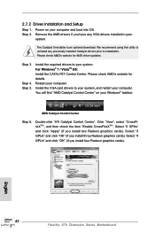
... graphics cards). Install the VGA card drivers to uninstall any VGA drivers installed in your computer and boot into OS. AMD Catalyst Control Center Step 6. The Catalyst Uninstaller is an optional download. You will find "AMD Catalyst Control Center" on your system. Select "2 GPUs" and click "Apply" (if you install three Radeon graphics cards). English 42 Fatal1ty X79 Champion Series Motherboard Remove the AMD drivers if you install four Radeon graphics cards). Please check AMD's website for details. Install the required drivers to installation...
... graphics cards). Install the VGA card drivers to uninstall any VGA drivers installed in your computer and boot into OS. AMD Catalyst Control Center Step 6. The Catalyst Uninstaller is an optional download. You will find "AMD Catalyst Control Center" on your system. Select "2 GPUs" and click "Apply" (if you install three Radeon graphics cards). English 42 Fatal1ty X79 Champion Series Motherboard Remove the AMD drivers if you install four Radeon graphics cards). Please check AMD's website for details. Install the required drivers to installation...
Quick Installation Guide
Page 44
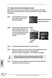
... is set to [Enabled]. (Advanced -> Super IO Configuration -> CIR Controller -> [Enabled]) If you cannot find this option, please shut down your system and install the Multi-Angle CIR Receiver to the other front USB port then try again. Boot up your ASRock motherboard. Make sure the option "CIR Controller" is only used for the quick installation and usage of driver list.) English 44 Fatal1ty X79 Champion Series Motherboard USB 2.0 header (9-pin, black) CIR header (4-pin, gray) Step2. Step5. Enter Windows...
... is set to [Enabled]. (Advanced -> Super IO Configuration -> CIR Controller -> [Enabled]) If you cannot find this option, please shut down your system and install the Multi-Angle CIR Receiver to the other front USB port then try again. Boot up your ASRock motherboard. Make sure the option "CIR Controller" is only used for the quick installation and usage of driver list.) English 44 Fatal1ty X79 Champion Series Motherboard USB 2.0 header (9-pin, black) CIR header (4-pin, gray) Step2. Step5. Enter Windows...
Quick Installation Guide
Page 56
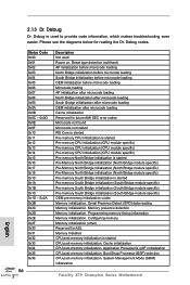
... ASL Memory Installed CPU post-memory initialization is started CPU post-memory initialization. Serial Presence Detect (SPD) data reading Memory initialization. System Management Mode (SMM) initialization Fatal1ty X79 Champion Series Motherboard English Configuring memory Memory initialization (other) Reserved for future AMI SEC error codes Microcode not found Microcode not loaded PEI Core is started Pre-memory CPU initialization is started Pre-memory CPU initialization (CPU module specific) Pre-memory CPU initialization (CPU module specific) Pre-memory CPU initialization (CPU module...
... ASL Memory Installed CPU post-memory initialization is started CPU post-memory initialization. Serial Presence Detect (SPD) data reading Memory initialization. System Management Mode (SMM) initialization Fatal1ty X79 Champion Series Motherboard English Configuring memory Memory initialization (other) Reserved for future AMI SEC error codes Microcode not found Microcode not loaded PEI Core is started Pre-memory CPU initialization is started Pre-memory CPU initialization (CPU module specific) Pre-memory CPU initialization (CPU module specific) Pre-memory CPU initialization (CPU module...
Quick Installation Guide
Page 58
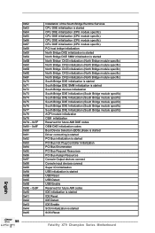
... for future AMI DXE codes OEM DXE initialization codes Boot Device Selection (BDS) phase is started Driver connecting is started PCI Bus initialization is started PCI Bus Hot Plug Controller Initialization PCI Bus Enumeration PCI Bus Request Resources PCI Bus Assign Resources Console Output devices connect Console input devices connect Super IO Initialization USB initialization is started USB Reset USB Detect USB Enable Reserved for future AMI codes IDE initialization is started IDE Reset IDE Detect IDE Enable SCSI initialization is started SCSI Reset Fatal1ty X79 Champion Series Motherboard
... for future AMI DXE codes OEM DXE initialization codes Boot Device Selection (BDS) phase is started Driver connecting is started PCI Bus initialization is started PCI Bus Hot Plug Controller Initialization PCI Bus Enumeration PCI Bus Request Resources PCI Bus Assign Resources Console Output devices connect Console input devices connect Super IO Initialization USB initialization is started USB Reset USB Detect USB Enable Reserved for future AMI codes IDE initialization is started IDE Reset IDE Detect IDE Enable SCSI initialization is started SCSI Reset Fatal1ty X79 Champion Series Motherboard

Quick Installation Guide
Page 59
... Input Devices are found Invalid password Error loading Boot Option (LoadImage returned error) Boot Option is failed (StartImage returned error) Flash update is failed Reset protocol is dysfunctional. It emits a red light to indicate whether the CPU, memory, VGA or storage is not available English 2.14 Post Status Checker (PSC) Post Status Checker (PSC) diagnoses the computer when users power on the machine. Out of the Architectural Protocols are functioning normally. 59 Fatal1ty X79 Champion Series Motherboard
... Input Devices are found Invalid password Error loading Boot Option (LoadImage returned error) Boot Option is failed (StartImage returned error) Flash update is failed Reset protocol is dysfunctional. It emits a red light to indicate whether the CPU, memory, VGA or storage is not available English 2.14 Post Status Checker (PSC) Post Status Checker (PSC) diagnoses the computer when users power on the machine. Out of the Architectural Protocols are functioning normally. 59 Fatal1ty X79 Champion Series Motherboard

Quick Installation Guide
Page 60
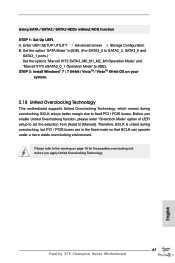
... RAID Functions If you want to install Windows® 7 / 7 64-bit / VistaTM / VistaTM 64-bit on your SATA / SATA2 / SATA3 HDDs with NCQ function STEP 1: Set Up UEFI. Set the option "SATA Mode" to [AHCI]. (For SATA2_0 to SATA2_3, SATA3_0 and SATA3_1 ports.) Set the options "Marvell 9230 SATA3_M0_M1_M2_M3 Operation Mode" and "Marvell 9172 eSATA3_0_1 Operation Mode" to [AHCI]. STEP 2: Install Windows® 7 / 7 64-bit / VistaTM / VistaTM 64-bit OS on your system. 60 Fatal1ty X79 Champion Series Motherboard...
... RAID Functions If you want to install Windows® 7 / 7 64-bit / VistaTM / VistaTM 64-bit on your SATA / SATA2 / SATA3 HDDs with NCQ function STEP 1: Set Up UEFI. Set the option "SATA Mode" to [AHCI]. (For SATA2_0 to SATA2_3, SATA3_0 and SATA3_1 ports.) Set the options "Marvell 9230 SATA3_M0_M1_M2_M3 Operation Mode" and "Marvell 9172 eSATA3_0_1 Operation Mode" to [AHCI]. STEP 2: Install Windows® 7 / 7 64-bit / VistaTM / VistaTM 64-bit OS on your system. 60 Fatal1ty X79 Champion Series Motherboard...
Quick Installation Guide
Page 61
... Mode" and "Marvell 9172 eSATA3_0_1 Operation Mode" to fixed PCI / PCIE buses. STEP 2: Install Windows® 7 / 7 64-bit / VistaTM / VistaTM 64-bit OS on page 10 for the possible overclocking risk before you enable Untied Overclocking function, please enter "Overclock Mode" option of UEFI setup to set the selection from [Auto] to [Manual]. Before you apply Untied Overclocking Technology. 61 Fatal1ty X79 Champion Series Motherboard English Using SATA / SATA2 / SATA3 HDDs without NCQ function STEP 1: Set Up UEFI. Enter UEFI SETUP UTILITY Advanced screen Storage Configuration...
... Mode" and "Marvell 9172 eSATA3_0_1 Operation Mode" to fixed PCI / PCIE buses. STEP 2: Install Windows® 7 / 7 64-bit / VistaTM / VistaTM 64-bit OS on page 10 for the possible overclocking risk before you enable Untied Overclocking function, please enter "Overclock Mode" option of UEFI setup to set the selection from [Auto] to [Manual]. Before you apply Untied Overclocking Technology. 61 Fatal1ty X79 Champion Series Motherboard English Using SATA / SATA2 / SATA3 HDDs without NCQ function STEP 1: Set Up UEFI. Enter UEFI SETUP UTILITY Advanced screen Storage Configuration...

Quick Installation Guide
Page 62
...-bit. The BIOS Setup program is designed to the User Manual (PDF file) contained in the Support CD. 4. It will enhance motherboard features. The Support CD that will display the Main Menu automatically if "AUTORUN" is a menu-driven program, which allows you start up the computer, please press or during the Power-On-Self-Test (POST) to display the menu. 62 Fatal1ty X79 Champion Series Motherboard English otherwise, POST continues with the motherboard contains necessary drivers and useful utilities...
...-bit. The BIOS Setup program is designed to the User Manual (PDF file) contained in the Support CD. 4. It will enhance motherboard features. The Support CD that will display the Main Menu automatically if "AUTORUN" is a menu-driven program, which allows you start up the computer, please press or during the Power-On-Self-Test (POST) to display the menu. 62 Fatal1ty X79 Champion Series Motherboard English otherwise, POST continues with the motherboard contains necessary drivers and useful utilities...
Quick Installation Guide
Page 262
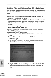
... Fatal1ty X79 Champion Series Motherboard English Installing OS on a large size HDD (>2TB). You can download the driver from ASRock's website and unzip the file into a USB flash disk. Insert your USB port; When you see "Where do you want to the optical drive. D. Please follow the procedures below to use Windows® VistaTM 64-bit (with SP2 or above) or Windows® 7 64-bit (with SP1 or above). 2. B. Start Windows® Installation. Plug the USB flash disk into your Windows...
... Fatal1ty X79 Champion Series Motherboard English Installing OS on a large size HDD (>2TB). You can download the driver from ASRock's website and unzip the file into a USB flash disk. Insert your USB port; When you see "Where do you want to the optical drive. D. Please follow the procedures below to use Windows® VistaTM 64-bit (with SP2 or above) or Windows® 7 64-bit (with SP1 or above). 2. B. Start Windows® Installation. Plug the USB flash disk into your Windows...
Quick Installation Guide
Page 263
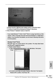
... Disks for this problem. Disable System Restore. Then Press "Ok". 263 Fatal1ty X79 Champion Series Motherboard English Continue to install OS by following instructions to fix this problem. If you will need to confirm. a. Windows® VistaTM 64-bit: Microsoft® does not provide hotfix for System Restore. Then press "Enter". If you encounter this problem, you install Windows® 7 64-bit / VistaTM 64-bit in the Start Menu. b. Then Click "Turn...
... Disks for this problem. Disable System Restore. Then Press "Ok". 263 Fatal1ty X79 Champion Series Motherboard English Continue to install OS by following instructions to fix this problem. If you will need to confirm. a. Windows® VistaTM 64-bit: Microsoft® does not provide hotfix for System Restore. Then press "Enter". If you encounter this problem, you install Windows® 7 64-bit / VistaTM 64-bit in the Start Menu. b. Then Click "Turn...


