

User Manual
Page 3
... 4.4.7 USB Configuration 56 4.4.8 Trusted Computing 57 4.5 Tool 58 4.6 Hardware Health Event Monitoring Screen 61 Installation 10 Pre-installation Precautions 10 2.1 CPU Installation 11 2.2 Installation of CPU Fan and Heatsink 12 2.3 Installation of Memory Modules (DIMM 13 2.4 Expansion Slots (PCI and PCI Express Slots 15 2.5 Jumpers Setup 16 2.6 Onboard Headers and Connectors 17 2.7 CrossFireXTM and Quad CrossFireXTM Operation Guide 22 2.8 Dual Graphics Operation Guide 25 3. Introduction 1 1.1 Package Contents 1 1.2 Specifications 2 1.3 Motherboard Layout 6 1.4 I/O Panel...
... 4.4.7 USB Configuration 56 4.4.8 Trusted Computing 57 4.5 Tool 58 4.6 Hardware Health Event Monitoring Screen 61 Installation 10 Pre-installation Precautions 10 2.1 CPU Installation 11 2.2 Installation of CPU Fan and Heatsink 12 2.3 Installation of Memory Modules (DIMM 13 2.4 Expansion Slots (PCI and PCI Express Slots 15 2.5 Jumpers Setup 16 2.6 Onboard Headers and Connectors 17 2.7 CrossFireXTM and Quad CrossFireXTM Operation Guide 22 2.8 Dual Graphics Operation Guide 25 3. Introduction 1 1.1 Package Contents 1 1.2 Specifications 2 1.3 Motherboard Layout 6 1.4 I/O Panel...
User Manual
Page 5
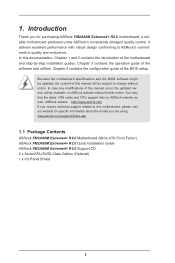
...latest VGA cards and CPU support lists on ASRock website without notice. Because the motherboard specifications and the BIOS software might be updated, the content of the motherboard and step-by-step installation guides. In this manual occur, the updated version will be available on ASRock website as well. www.asrock.com/support/index.asp 1.1 Package Contents ASRock FM2A88M Extreme4+ R2.0 Motherboard (Micro ATX Form Factor) ASRock FM2A88M Extreme4+ R2.0 Quick Installation Guide ASRock FM2A88M Extreme4+ R2.0 Support CD 2 x Serial ATA (SATA) Data Cables (Optional) 1 x I/O Panel...
...latest VGA cards and CPU support lists on ASRock website without notice. Because the motherboard specifications and the BIOS software might be updated, the content of the motherboard and step-by-step installation guides. In this manual occur, the updated version will be available on ASRock website as well. www.asrock.com/support/index.asp 1.1 Package Contents ASRock FM2A88M Extreme4+ R2.0 Motherboard (Micro ATX Form Factor) ASRock FM2A88M Extreme4+ R2.0 Quick Installation Guide ASRock FM2A88M Extreme4+ R2.0 Support CD 2 x Serial ATA (SATA) Data Cables (Optional) 1 x I/O Panel...

User Manual
Page 8
...pin, 1 x 3-pin) - 1 x Chassis Fan Connector (4-pin) - 1 x Power Fan Connector (3-pin) - 1 x 24 pin ATX Power Connector - 1 x 8 pin 12V Power Connector - 1 x Front Panel Audio Connector - 3 x USB 2.0 Headers (Support 6 USB 2.0 ports) (Supports ESD Protection (ASRock Full Spike Protection)) - 1 x USB 3.0 Header by AMD A88X (Bolton-D4) (Supports 2 USB 3.0 ports) (Supports ESD Protection (ASRock Full Spike Protection)) BIOS Feature - 64Mb AMI UEFI Legal BIOS with GUI support - CPU temperature sensing Monitor - CPU/Chassis Quiet Fan - FCC, CE, WHQL - Microsoft® Windows...
...pin, 1 x 3-pin) - 1 x Chassis Fan Connector (4-pin) - 1 x Power Fan Connector (3-pin) - 1 x 24 pin ATX Power Connector - 1 x 8 pin 12V Power Connector - 1 x Front Panel Audio Connector - 3 x USB 2.0 Headers (Support 6 USB 2.0 ports) (Supports ESD Protection (ASRock Full Spike Protection)) - 1 x USB 3.0 Header by AMD A88X (Bolton-D4) (Supports 2 USB 3.0 ports) (Supports ESD Protection (ASRock Full Spike Protection)) BIOS Feature - 64Mb AMI UEFI Legal BIOS with GUI support - CPU temperature sensing Monitor - CPU/Chassis Quiet Fan - FCC, CE, WHQL - Microsoft® Windows...

User Manual
Page 11
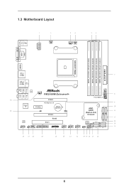
... Power Fan Connector (PWR_FAN1) 3 CPU Fan Connector (CPU_FAN1) 4 CPU Fan Connector (CPU_FAN2) 5 2 x 240-pin DDR3 DIMM Slots (DDR3_A1, DDR3_B1) 6 2 x 240-pin DDR3 DIMM Slots (DDR3_A2, DDR3_B2) 7 ATX Power Connector (ATXPWR1) 8 USB 3.0 Header (USB3_3_4) 9 Clear CMOS Jumper (CLRCMOS1) 10 SATA3 Connector (SATA3_7) 11 SATA3 Connector (SATA3_8) 12 SATA3 Connector (SATA3_6) 13 SATA3 Connector (SATA3_5) 14 SATA3 Connector (SATA3_4) 15 SATA3 Connector (SATA3_3) 16 SATA3 Connector (SATA3_1) 17 SATA3 Connector (SATA3_2) 18 System Panel Header (PANEL1) 19 Power LED Header (PLED1) 20 Chassis Speaker Header...
... Power Fan Connector (PWR_FAN1) 3 CPU Fan Connector (CPU_FAN1) 4 CPU Fan Connector (CPU_FAN2) 5 2 x 240-pin DDR3 DIMM Slots (DDR3_A1, DDR3_B1) 6 2 x 240-pin DDR3 DIMM Slots (DDR3_A2, DDR3_B2) 7 ATX Power Connector (ATXPWR1) 8 USB 3.0 Header (USB3_3_4) 9 Clear CMOS Jumper (CLRCMOS1) 10 SATA3 Connector (SATA3_7) 11 SATA3 Connector (SATA3_8) 12 SATA3 Connector (SATA3_6) 13 SATA3 Connector (SATA3_5) 14 SATA3 Connector (SATA3_4) 15 SATA3 Connector (SATA3_3) 16 SATA3 Connector (SATA3_1) 17 SATA3 Connector (SATA3_2) 18 System Panel Header (PANEL1) 19 Power LED Header (PLED1) 20 Chassis Speaker Header...
User Manual
Page 14
... bit, 240-pin module) DDR3_B2 (64 bit, 240-pin module) ATXPWR1 1.3 Motherboard Layout PS2 Keyboard/ Mouse USB 2.0 T: USB3 B: USB4 ATX12V1 PWR_FAN1 CPU_FAN1 CPU_FAN2 DVI1 VGA1 SOCKET FM2b HDMI1 Bottom: Optical SPDIF Bottom: MIC IN USB 3.0 T: USB1 B: USB2 USB 2.0 T: USB1 Top: B: USB2 RJ-45 Top: CTR BASS Center: REAR SPK LAN CHA_FAN1 FM2A88M Extreme4+ Top: LINE IN Center: FRONT Super I/O AUDIO CODEC HD_AUDIO1 1 IR1 1 PCIE1 PCI Express 3.0 PCIE2 CI1 1 CMOS BATTERY...
... bit, 240-pin module) DDR3_B2 (64 bit, 240-pin module) ATXPWR1 1.3 Motherboard Layout PS2 Keyboard/ Mouse USB 2.0 T: USB3 B: USB4 ATX12V1 PWR_FAN1 CPU_FAN1 CPU_FAN2 DVI1 VGA1 SOCKET FM2b HDMI1 Bottom: Optical SPDIF Bottom: MIC IN USB 3.0 T: USB1 B: USB2 USB 2.0 T: USB1 Top: B: USB2 RJ-45 Top: CTR BASS Center: REAR SPK LAN CHA_FAN1 FM2A88M Extreme4+ Top: LINE IN Center: FRONT Super I/O AUDIO CODEC HD_AUDIO1 1 IR1 1 PCIE1 PCI Express 3.0 PCIE2 CI1 1 CMOS BATTERY...

User Manual
Page 15
... Power Fan Connector (PWR_FAN1) 3 CPU Fan Connector (CPU_FAN1) 4 CPU Fan Connector (CPU_FAN2) 5 2 x 240-pin DDR3 DIMM Slots (DDR3_A1, DDR3_B1) 6 2 x 240-pin DDR3 DIMM Slots (DDR3_A2, DDR3_B2) 7 ATX Power Connector (ATXPWR1) 8 USB 3.0 Header (USB3_3_4) 9 Clear CMOS Jumper (CLRCMOS1) 10 SATA3 Connector (SATA3_7) 11 SATA3 Connector (SATA3_8) 12 SATA3 Connector (SATA3_6) 13 SATA3 Connector (SATA3_5) 14 SATA3 Connector (SATA3_4) 15 SATA3 Connector (SATA3_3) 16 SATA3 Connector (SATA3_1) 17 SATA3 Connector (SATA3_2) 18 System Panel Header (PANEL1) 19 Power LED Header (PLED1) 20 Chassis Speaker Header...
... Power Fan Connector (PWR_FAN1) 3 CPU Fan Connector (CPU_FAN1) 4 CPU Fan Connector (CPU_FAN2) 5 2 x 240-pin DDR3 DIMM Slots (DDR3_A1, DDR3_B1) 6 2 x 240-pin DDR3 DIMM Slots (DDR3_A2, DDR3_B2) 7 ATX Power Connector (ATXPWR1) 8 USB 3.0 Header (USB3_3_4) 9 Clear CMOS Jumper (CLRCMOS1) 10 SATA3 Connector (SATA3_7) 11 SATA3 Connector (SATA3_8) 12 SATA3 Connector (SATA3_6) 13 SATA3 Connector (SATA3_5) 14 SATA3 Connector (SATA3_4) 15 SATA3 Connector (SATA3_3) 16 SATA3 Connector (SATA3_1) 17 SATA3 Connector (SATA3_2) 18 System Panel Header (PANEL1) 19 Power LED Header (PLED1) 20 Chassis Speaker Header...
User Manual
Page 24
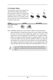
... chassis intrusion status. 16 After waiting for 5 seconds. Please be noted that the password, date, time, user default profile, 1394 GUID and MAC address will be detected. If no jumper cap is placed on pins, the jumper is removed. However, please do the clear-CMOS ac- Please adjust the BIOS option "Clear Status" to default setup, please turn off the computer and unplug the power cord from the power supply...
... chassis intrusion status. 16 After waiting for 5 seconds. Please be noted that the password, date, time, user default profile, 1394 GUID and MAC address will be detected. If no jumper cap is placed on pins, the jumper is removed. However, please do the clear-CMOS ac- Please adjust the BIOS option "Clear Status" to default setup, please turn off the computer and unplug the power cord from the power supply...
User Manual
Page 30
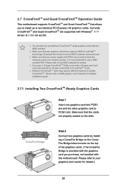
... use a AMD certified PSU. Download the drivers from the AMD's website: www.amd.com 3. Different CrossFireXTM cards may require different methods to PCIE3 slot. Please refer to AMD graphics card manuals for detailed installation guide. 2.7.1 Installing Two CrossFireXTM-Ready Graphics Cards Step 1 Insert one graphics card into PCIE1 slot and the other graphics card to enable CrossFireXTM. It is provided with the graphics card you purchase, not bundled with this motherboard. CrossFire Bridge Step 2 Connect two graphics cards by installing...
... use a AMD certified PSU. Download the drivers from the AMD's website: www.amd.com 3. Different CrossFireXTM cards may require different methods to PCIE3 slot. Please refer to AMD graphics card manuals for detailed installation guide. 2.7.1 Installing Two CrossFireXTM-Ready Graphics Cards Step 1 Insert one graphics card into PCIE1 slot and the other graphics card to enable CrossFireXTM. It is provided with the graphics card you purchase, not bundled with this motherboard. CrossFire Bridge Step 2 Connect two graphics cards by installing...
User Manual
Page 32
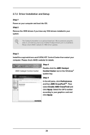
... to uninstall any VGA drivers installed in the Windows® system tray. We recommend using this utility to your computer and boot into OS. Please check AMD's website for AMD driver updates. Then select Enable AMD CrossFireX and click Apply. The Catalyst Uninstaller is an optional download. AMD Catalyst Control Center Step 4 Double-click the AMD Catalyst Control Center icon in your computer. 2.7.2 Driver Installation and Setup Step 1 Power on your graphics card and click...
... to uninstall any VGA drivers installed in the Windows® system tray. We recommend using this utility to your computer and boot into OS. Please check AMD's website for AMD driver updates. Then select Enable AMD CrossFireX and click Apply. The Catalyst Uninstaller is an optional download. AMD Catalyst Control Center Step 4 Double-click the AMD Catalyst Control Center icon in your computer. 2.7.2 Driver Installation and Setup Step 1 Power on your graphics card and click...
User Manual
Page 33
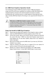
... current VGA driver / VBIOS can allow Dual Graphics output from our support CD to PCIE1 slot. For any VGA driver installed in a Windows® 8.1 / 7 environment. 2.8 AMD Dual Graphics Operation Guide This motherboard supports AMD Dual Graphics feature. What does an AMD Dual Graphics system include? Connect the monitor cable to enter AMD VISION Engine Control Center. 25 An AMD Dual Graphics system includes an AMD Radeon R7/R5 series graphics processor and a motherboard based on [Auto]. Click "AMD VISION Engine Control Center" to the onboard VGA port. Step 2. AMD Dual Graphics...
... current VGA driver / VBIOS can allow Dual Graphics output from our support CD to PCIE1 slot. For any VGA driver installed in a Windows® 8.1 / 7 environment. 2.8 AMD Dual Graphics Operation Guide This motherboard supports AMD Dual Graphics feature. What does an AMD Dual Graphics system include? Connect the monitor cable to enter AMD VISION Engine Control Center. 25 An AMD Dual Graphics system includes an AMD Radeon R7/R5 series graphics processor and a motherboard based on [Auto]. Click "AMD VISION Engine Control Center" to the onboard VGA port. Step 2. AMD Dual Graphics...
User Manual
Page 35
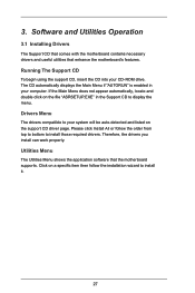
... drivers you install can work properly. Running The Support CD To begin using the support CD, insert the CD into your system will be auto-detected and listed on a specific item then follow the order from top to bottom to install those required drivers. Software and Utilities Operation 3.1 Installing Drivers The Support CD that comes with the motherboard contains necessary drivers and useful utilities that the motherboard supports. Drivers Menu The drivers compatible to your CD-ROM drive...
... drivers you install can work properly. Running The Support CD To begin using the support CD, insert the CD into your system will be auto-detected and listed on a specific item then follow the order from top to bottom to install those required drivers. Software and Utilities Operation 3.1 Installing Drivers The Support CD that comes with the motherboard contains necessary drivers and useful utilities that the motherboard supports. Drivers Menu The drivers compatible to your CD-ROM drive...
User Manual
Page 51
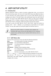
... selections: Main For setting system time/date information OC Tweaker For overclocking configurations Advanced For advanced system configurations Tool Useful tools H/W Monitor Displays current hardware status Boot For configuring boot settings and boot priority Security For security settings Exit Exit the current screen or the UEFI SETUP UTILITY Use < > key or < > key to choose among the selections on the motherboard stores the UEFI SETUP UTILITY. The UEFI chip on the menu bar, and use the UEFI SETUP UTILITY to enter the UEFI SETUP UTILITY, otherwise, POST will...
... selections: Main For setting system time/date information OC Tweaker For overclocking configurations Advanced For advanced system configurations Tool Useful tools H/W Monitor Displays current hardware status Boot For configuring boot settings and boot priority Security For security settings Exit Exit the current screen or the UEFI SETUP UTILITY Use < > key or < > key to choose among the selections on the motherboard stores the UEFI SETUP UTILITY. The UEFI chip on the menu bar, and use the UEFI SETUP UTILITY to enter the UEFI SETUP UTILITY, otherwise, POST will...

User Manual
Page 55
... allows memory accesses to enable Channel Memory Interleaving. APU PCIE Voltage VDDP Use this to select DRAM Voltage. Configuration options: [Disabled], [Auto]. The default value is [Auto]. Voltage Configuration DRAM Voltage Use this to select APU PCIE Voltage VDDP. The default value is [Auto]. The default value is [Auto]. SB Voltage Use this item to view SPD data. Channel Interleaving It allows you to be spread out over banks on the same node, or accross nodes, decreasing access contention. DRAM Timing Control DRAM Slot Use this...
... allows memory accesses to enable Channel Memory Interleaving. APU PCIE Voltage VDDP Use this to select DRAM Voltage. Configuration options: [Disabled], [Auto]. The default value is [Auto]. Voltage Configuration DRAM Voltage Use this to select APU PCIE Voltage VDDP. The default value is [Auto]. The default value is [Auto]. SB Voltage Use this item to view SPD data. Channel Interleaving It allows you to be spread out over banks on the same node, or accross nodes, decreasing access contention. DRAM Timing Control DRAM Slot Use this...

User Manual
Page 57
... compatibility issue with some memory modules or power supplies. The default value is [Auto]. 49 Please note that enabling this function may reduce CPU voltage and memory frequency, and lead to enable or disable Package C6 mode. Configuration options: [Enabled] and [Disabled]. The default value is [Disabled]. Please set this item to [Disable] if above issue occurs. CPU Thermal Throttle Use this item to enable CPU internal thermal control mechanism to enable or disable AMD's Cool 'n' QuietTM technology. If you enable the item "Core...
... compatibility issue with some memory modules or power supplies. The default value is [Auto]. 49 Please note that enabling this function may reduce CPU voltage and memory frequency, and lead to enable or disable Package C6 mode. Configuration options: [Enabled] and [Disabled]. The default value is [Disabled]. Please set this item to [Disable] if above issue occurs. CPU Thermal Throttle Use this item to enable CPU internal thermal control mechanism to enable or disable AMD's Cool 'n' QuietTM technology. If you enable the item "Core...

User Manual
Page 58
... Primary VGA in case of multiple video controllers. The default value is [PCI Express]. Configuration options: [Auto], [32MB], [64MB], [128MB], [256MB] [512MB], [1GB] and [2GB]. Dual Graphics This item appears only when you install the DVI to HDMI adapter to DVI port. The default value is [as HDMI]. Primary Graphics Adapter This item will be automatically enabled when you enable this motherboard. If you select [as Dual Link DVI], you can use HDMI monitor with audio...
... Primary VGA in case of multiple video controllers. The default value is [PCI Express]. Configuration options: [Auto], [32MB], [64MB], [128MB], [256MB] [512MB], [1GB] and [2GB]. Dual Graphics This item appears only when you install the DVI to HDMI adapter to DVI port. The default value is [as HDMI]. Primary Graphics Adapter This item will be automatically enabled when you enable this motherboard. If you select [as Dual Link DVI], you can use HDMI monitor with audio...
User Manual
Page 60
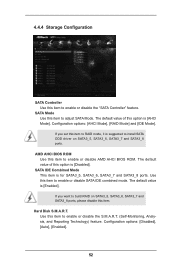
... ports. Hard Disk S.M.A.R.T. Use this item to enable or disable the S.M.A.R.T. (Self-Monitoring, Analysis, and Reporting Technology) feature. Use this item to enable or disable SATA IDE combined mode. If you want to install SATA ODD driver on SATA3_5, SATA3_6, SATA3_7 and SATA3_8 ports, please disable this item. AMD AHCI BIOS ROM Use this item to enable or disable the "SATA Controller" feature. The default value of this option is [Enabled]. If you set this item to adjust SATA Mode. Configuration options: [Disabled], [Auto], [Enabled]. 52 4.4.4 Storage Configuration...
... ports. Hard Disk S.M.A.R.T. Use this item to enable or disable the S.M.A.R.T. (Self-Monitoring, Analysis, and Reporting Technology) feature. Use this item to enable or disable SATA IDE combined mode. If you want to install SATA ODD driver on SATA3_5, SATA3_6, SATA3_7 and SATA3_8 ports, please disable this item. AMD AHCI BIOS ROM Use this item to enable or disable the "SATA Controller" feature. The default value of this option is [Enabled]. If you set this item to adjust SATA Mode. Configuration options: [Disabled], [Auto], [Enabled]. 52 4.4.4 Storage Configuration...

User Manual
Page 62
... set the power state after S3 only when the hard disk is selected, the AC/power resumes and the system starts to boot up when the power recovers. Check Ready Bit Enable to enter the operating system after an unexpected AC/power loss. If [Power On] is ready, this item to enable or disable PCI devices to turn on the system. 54 PS/2 Keyboard Power On Use this item to enable or disable...
... set the power state after S3 only when the hard disk is selected, the AC/power resumes and the system starts to boot up when the power recovers. Check Ready Bit Enable to enter the operating system after an unexpected AC/power loss. If [Power On] is ready, this item to enable or disable PCI devices to turn on the system. 54 PS/2 Keyboard Power On Use this item to enable or disable...

User Manual
Page 64
... select [Disabled] to use under UEFI setup and Windows / Linux OS. USB devices are not allowed to enter OS. [UEFI Setup Only] - The default value is [Enabled]. 56 Legacy USB 3.0 Support Use this option to use of USB 2.0 controller. Enables support for USB devices. The default value is [Enabled]. There are connected. [Disabled] - Enables legacy support if USB devices are four confi guration options: [Enabled], [Auto], [Disabled] and [UEFI Setup Only]. A88X USB 3.0 Controller Use this option to below descriptions for USB 3.0 devices. Legacy USB Support Use this...
... select [Disabled] to use under UEFI setup and Windows / Linux OS. USB devices are not allowed to enter OS. [UEFI Setup Only] - The default value is [Enabled]. 56 Legacy USB 3.0 Support Use this option to use of USB 2.0 controller. Enables support for USB devices. The default value is [Enabled]. There are connected. [Disabled] - Enables legacy support if USB devices are four confi guration options: [Enabled], [Auto], [Disabled] and [UEFI Setup Only]. A88X USB 3.0 Controller Use this option to below descriptions for USB 3.0 devices. Legacy USB Support Use this...
User Manual
Page 66
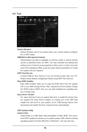
... your USB storage device. Easy Driver Installer For users that installs the LAN driver to your system via OMG. Please setup network configuration before using UEFI Tech Service. UEFI Update Utility Instant Flash Instant Flash is a UEFI flash utility embedded in the UEFI that don't have an optical disk drive to prevent users from our support CD, Easy Driver Installer is a handy tool in Flash ROM. Just save the new 58 Easy RAID Installer Easy RAID Installer helps you are having trouble with your current system configuration in RAID mode...
... your USB storage device. Easy Driver Installer For users that installs the LAN driver to your system via OMG. Please setup network configuration before using UEFI Tech Service. UEFI Update Utility Instant Flash Instant Flash is a UEFI flash utility embedded in the UEFI that don't have an optical disk drive to prevent users from our support CD, Easy Driver Installer is a handy tool in Flash ROM. Just save the new 58 Easy RAID Installer Easy RAID Installer helps you are having trouble with your current system configuration in RAID mode...

User Manual
Page 69
... [Full On]. The default is [Enabled]. Chassis Fan 1 Setting This allows you to enable or disable case open has been detected. Clear Status This option appears only when the case open detection feature. Use this item to enable or disable Over Temperature Protection. Confi guration options: [Full On], [Manual Mode] and [Automatic Mode]. The default is value [Disabled]. Case Open Feature This allows you to set the CPU fan 1 & 2 speed. 4.6 Hardware Health Event Monitoring Screen In this section...
... [Full On]. The default is [Enabled]. Chassis Fan 1 Setting This allows you to enable or disable case open has been detected. Clear Status This option appears only when the case open detection feature. Use this item to enable or disable Over Temperature Protection. Confi guration options: [Full On], [Manual Mode] and [Automatic Mode]. The default is value [Disabled]. Case Open Feature This allows you to set the CPU fan 1 & 2 speed. 4.6 Hardware Health Event Monitoring Screen In this section...


