RAID Installation Guide
Page 5
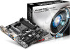
... you want to install Windows® 8 / 8 64-bit / 7 / 7 64-bit on a RAID disk composed of the USB port. B. Go to . STEP 2: Create and configure the RAID disk A. Follow the instruction inside the RAID ROM utility to create the target RAID disk. (Please refer to Section 1.4 in MBR mode which support IDE Combined Mode. B. Plug a USB drive into the DVD-ROM drive. Follow instructions to enter UEFI setup utility. During system boot, press or key to finish the driver copy process. E. Go to enter UEFI setup utility. Click to finish...
... you want to install Windows® 8 / 8 64-bit / 7 / 7 64-bit on a RAID disk composed of the USB port. B. Go to . STEP 2: Create and configure the RAID disk A. Follow the instruction inside the RAID ROM utility to create the target RAID disk. (Please refer to Section 1.4 in MBR mode which support IDE Combined Mode. B. Plug a USB drive into the DVD-ROM drive. Follow instructions to enter UEFI setup utility. During system boot, press or key to finish the driver copy process. E. Go to enter UEFI setup utility. Click to finish...

RAID Installation Guide
Page 15
... AMD SATA RAID controllers. Follow the prompts in as the Administrator. 2. RAIDXpert uses this guide carefully and follow the instructions below to configure and manage RAID functions. 2.1 Components of RAIDXpert Installation Software RAIDXpert installation software will install two major components to install RAIDXpert on a network. Boot the PC or server, launch Windows, and log in the installation dialog boxes. 6. When the first installation screen appears, choose an installer language from the dropdown menu...
... AMD SATA RAID controllers. Follow the prompts in as the Administrator. 2. RAIDXpert uses this guide carefully and follow the instructions below to configure and manage RAID functions. 2.1 Components of RAIDXpert Installation Software RAIDXpert installation software will install two major components to install RAIDXpert on a network. Boot the PC or server, launch Windows, and log in the installation dialog boxes. 6. When the first installation screen appears, choose an installer language from the dropdown menu...
User Manual
Page 3
...4.4.4 Storage Configuration 56 4.4.5 Super IO Configuration 57 4.4.6 ACPI Configuration 58 4.4.7 USB Configuration 60 4.4.8 Trusted Computing 61 Software and Utilities Operation 32 3.1 Installing Drivers 32 3.2 A-Tuning 33 3.3 Qualcomm® Atheros® Security Wake On Internet Technology... 37 3.4 Start8 44 4. Installation 15 Pre-installation Precautions 15 2.1 CPU Installation 16 2.2 Installation of CPU Fan and Heatsink 17 2.3 Installation of Memory Modules (DIMM 18 2.4 Expansion Slots (PCI and PCI Express Slots 20 2.5 Jumpers Setup 21 2.6 Onboard Headers and Connectors...
...4.4.4 Storage Configuration 56 4.4.5 Super IO Configuration 57 4.4.6 ACPI Configuration 58 4.4.7 USB Configuration 60 4.4.8 Trusted Computing 61 Software and Utilities Operation 32 3.1 Installing Drivers 32 3.2 A-Tuning 33 3.3 Qualcomm® Atheros® Security Wake On Internet Technology... 37 3.4 Start8 44 4. Installation 15 Pre-installation Precautions 15 2.1 CPU Installation 16 2.2 Installation of CPU Fan and Heatsink 17 2.3 Installation of Memory Modules (DIMM 18 2.4 Expansion Slots (PCI and PCI Express Slots 20 2.5 Jumpers Setup 21 2.6 Onboard Headers and Connectors...

User Manual
Page 8
...AMI UEFI Legal BIOS with overclocking, including adjusting the setting in the BIOS, applying Untied Overclocking Technology, or using third-party overclocking tools. Supports "Plug and Play" - Chassis temperature sensing - Overclocking may affect your system's stability, or even cause damage to the components and devices of your own risk and expense. CPU Fan Tachometer - It should be done at your system. - 3 x USB 2.0 Headers (Support 6 USB 2.0 ports) - 1 x USB 3.0 Header by overclocking. 4 ACPI 1.1 compliance wake up events - Drivers, Utilities, AntiVirus Software (Trial...
...AMI UEFI Legal BIOS with overclocking, including adjusting the setting in the BIOS, applying Untied Overclocking Technology, or using third-party overclocking tools. Supports "Plug and Play" - Chassis temperature sensing - Overclocking may affect your system's stability, or even cause damage to the components and devices of your own risk and expense. CPU Fan Tachometer - It should be done at your system. - 3 x USB 2.0 Headers (Support 6 USB 2.0 ports) - 1 x USB 3.0 Header by overclocking. 4 ACPI 1.1 compliance wake up events - Drivers, Utilities, AntiVirus Software (Trial...

User Manual
Page 13
... the RAID driver to your user experience and behavior. With the smart X-Boost, overclocking CPU can become a near one A-Tuning tuning program that installs the LAN driver to your USB storage device, please change your system via an USB storage device, then downloads and installs the other required drivers automatically. Simply press "X" when turning on the PC next time. ASRock Fast Boot With ASRock's exclusive Fast Boot technology, it hard to your CPUs. ASRock Restart to UEFI Windows®...
... the RAID driver to your user experience and behavior. With the smart X-Boost, overclocking CPU can become a near one A-Tuning tuning program that installs the LAN driver to your USB storage device, please change your system via an USB storage device, then downloads and installs the other required drivers automatically. Simply press "X" when turning on the PC next time. ASRock Fast Boot With ASRock's exclusive Fast Boot technology, it hard to your CPUs. ASRock Restart to UEFI Windows®...

User Manual
Page 16
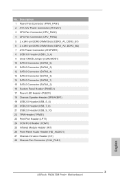
...Fan Connector (PWR_FAN1) 2 ATX 12V Power Connector (ATX12V1) 3 CPU Fan Connector (CPU_FAN1) 4 CPU Fan Connector (CPU_FAN2) 5 2 x 240-pin DDR3 DIMM Slots (DDR3_A1, DDR3_B1) 6 2 x 240-pin DDR3 DIMM Slots (DDR3_A2, DDR3_B2) 7 ATX Power Connector (ATXPWR1) 8 USB 3.0 Header (USB3_3_4) 9 Clear CMOS Jumper (CLRCMOS1) 10 SATA3 Connector (SATA3_6) 11 SATA3 Connector (SATA3_5) 12 SATA3 Connector (SATA3_4) 13 SATA3 Connector (SATA3_3) 14 SATA3 Connector (SATA3_1) 15 SATA3 Connector (SATA3_2) 16 System Panel Header (PANEL1) 17 Power LED Header (PLED1) 18 Chassis Speaker Header (SPEAKER1) 19 USB 2.0 Header...
...Fan Connector (PWR_FAN1) 2 ATX 12V Power Connector (ATX12V1) 3 CPU Fan Connector (CPU_FAN1) 4 CPU Fan Connector (CPU_FAN2) 5 2 x 240-pin DDR3 DIMM Slots (DDR3_A1, DDR3_B1) 6 2 x 240-pin DDR3 DIMM Slots (DDR3_A2, DDR3_B2) 7 ATX Power Connector (ATXPWR1) 8 USB 3.0 Header (USB3_3_4) 9 Clear CMOS Jumper (CLRCMOS1) 10 SATA3 Connector (SATA3_6) 11 SATA3 Connector (SATA3_5) 12 SATA3 Connector (SATA3_4) 13 SATA3 Connector (SATA3_3) 14 SATA3 Connector (SATA3_1) 15 SATA3 Connector (SATA3_2) 16 System Panel Header (PANEL1) 17 Power LED Header (PLED1) 18 Chassis Speaker Header (SPEAKER1) 19 USB 2.0 Header...

User Manual
Page 33
... using this utility to uninstall any VGA drivers installed in the Windows® system tray. AMD Catalyst Control Center Step 4 Double-click the AMD Catalyst Control Center icon in your graphics card and click Apply. 29 2.7.2 Driver Installation and Setup Step 1 Power on your computer. Step 3 Install the required drivers and CATALYST Control Center then restart your computer and boot into OS. Then select Enable AMD CrossFireX and click Apply. Step 2 Remove the AMD drivers...
... using this utility to uninstall any VGA drivers installed in the Windows® system tray. AMD Catalyst Control Center Step 4 Double-click the AMD Catalyst Control Center icon in your graphics card and click Apply. 29 2.7.2 Driver Installation and Setup Step 1 Power on your computer. Step 3 Install the required drivers and CATALYST Control Center then restart your computer and boot into OS. Then select Enable AMD CrossFireX and click Apply. Step 2 Remove the AMD drivers...
User Manual
Page 34
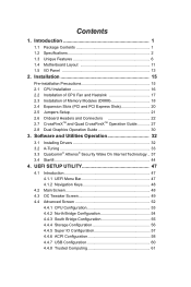
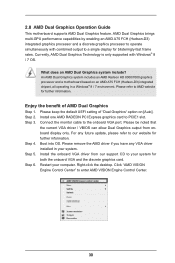
... computer. For any VGA driver installed in a Windows® 8 / 7 environment. Right-click the desktop. Click "AMD VISION Engine Control Center" to PCIE1 slot. An AMD Dual Graphics system includes an AMD Radeon HD 8000/7000 graphics processor and a motherboard based on [Auto]. Step 3. Step 5. Please keep the default UEFI setting of AMD Dual Graphics Step 1. Step 2. Connect the monitor cable to AMD website for both the onboard VGA and the discrete graphics card. Boot into OS. Install the onboard VGA driver from onboard display only. Please be...
... computer. For any VGA driver installed in a Windows® 8 / 7 environment. Right-click the desktop. Click "AMD VISION Engine Control Center" to PCIE1 slot. An AMD Dual Graphics system includes an AMD Radeon HD 8000/7000 graphics processor and a motherboard based on [Auto]. Step 3. Step 5. Please keep the default UEFI setting of AMD Dual Graphics Step 1. Step 2. Connect the monitor cable to AMD website for both the onboard VGA and the discrete graphics card. Boot into OS. Install the onboard VGA driver from onboard display only. Please be...

User Manual
Page 36
... drivers you install can work properly. Drivers Menu The drivers compatible to display the menu. Click on the support CD driver page. If the Main Menu does not appear automatically, locate and double click on the file "ASRSETUP.EXE" in your computer. 3. Utilities Menu The Utilities Menu shows the application software that enhance the motherboard's features. The CD automatically displays the Main Menu if "AUTORUN" is enabled in the Support CD to your CD-ROM drive. Please click Install...
... drivers you install can work properly. Drivers Menu The drivers compatible to display the menu. Click on the support CD driver page. If the Main Menu does not appear automatically, locate and double click on the file "ASRSETUP.EXE" in your computer. 3. Utilities Menu The Utilities Menu shows the application software that enhance the motherboard's features. The CD automatically displays the Main Menu if "AUTORUN" is enabled in the Support CD to your CD-ROM drive. Please click Install...
User Manual
Page 51
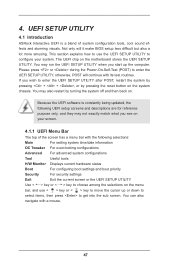
... ASRock Interactive UEFI is constantly being updated, the following selections: Main For setting system time/date information OC Tweaker For overclocking configurations Advanced For advanced system configurations Tool Useful tools H/W Monitor Displays current hardware status Boot For configuring boot settings and boot priority Security For security settings Exit Exit the current screen or the UEFI SETUP UTILITY Use < > key or < > key to choose among the selections on the menu bar, and use the UEFI SETUP UTILITY to enter the UEFI SETUP UTILITY after POST...
... ASRock Interactive UEFI is constantly being updated, the following selections: Main For setting system time/date information OC Tweaker For overclocking configurations Advanced For advanced system configurations Tool Useful tools H/W Monitor Displays current hardware status Boot For configuring boot settings and boot priority Security For security settings Exit Exit the current screen or the UEFI SETUP UTILITY Use < > key or < > key to choose among the selections on the menu bar, and use the UEFI SETUP UTILITY to enter the UEFI SETUP UTILITY after POST...
User Manual
Page 58
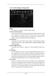
... type of Primary VGA in case of this to select DVI function when you to set the share memory feature. The default value of multiple video controllers. Configuration options: [as Dual Link DVI] and [as HDMI], you enable this to DVI port. It allows you can use Dual Link DVI monitor without audio function. If you can use HDMI monitor with audio function. Configuration options: [Onboard], [PCI] and [PCI Express]. The default value is [PCI Express]. Use this option, the primary monitor will switch the PCI Bus...
... type of Primary VGA in case of this to select DVI function when you to set the share memory feature. The default value of multiple video controllers. Configuration options: [as Dual Link DVI] and [as HDMI], you enable this to DVI port. It allows you can use Dual Link DVI monitor without audio function. If you can use HDMI monitor with audio function. Configuration options: [Onboard], [PCI] and [PCI Express]. The default value is [PCI Express]. Use this option, the primary monitor will switch the PCI Bus...

User Manual
Page 60
Hard Disk S.M.A.R.T. The default value is for SATA3_5 and SATA3_6 ports. Use this item to enable or disable AMD AHCI BIOS ROM. If you want to build RAID on SATA3_5 and SATA3_6 ports. AMD AHCI BIOS ROM Use this item to enable or disable the S.M.A.R.T. (Self-Monitoring, Analysis, and Reporting Technology) feature. Configuration options: [AHCI Mode], [RAID Mode] and [IDE Mode]. Use this item to enable or disable the "SATA Controller" feature. SATA IDE Combined Mode This item is [Enabled]. The default value of this item to RAID mode, it is [Disabled]. If you...
Hard Disk S.M.A.R.T. The default value is for SATA3_5 and SATA3_6 ports. Use this item to enable or disable AMD AHCI BIOS ROM. If you want to build RAID on SATA3_5 and SATA3_6 ports. AMD AHCI BIOS ROM Use this item to enable or disable the S.M.A.R.T. (Self-Monitoring, Analysis, and Reporting Technology) feature. Configuration options: [AHCI Mode], [RAID Mode] and [IDE Mode]. Use this item to enable or disable the "SATA Controller" feature. SATA IDE Combined Mode This item is [Enabled]. The default value of this item to RAID mode, it is [Disabled]. If you...

User Manual
Page 64
4.4.7 USB Configuration USB 2.0 Controller Use this item to enable or disable the use of USB 3.0 controller. There are connected. [Disabled] - Enables support for the details of these four options: [Enabled] - Enables legacy support if USB devices are four confi guration options: [Enabled], [Auto], [Disabled] and [UEFI Setup Only]. The default value is recommended to select [Disabled] to enter OS. [UEFI Setup Only] - USB devices are not allowed to enable or disable the use only under legacy OS and UEFI setup when [Disabled] is [Enabled]. 60 If you have USB compatibility ...
4.4.7 USB Configuration USB 2.0 Controller Use this item to enable or disable the use of USB 3.0 controller. There are connected. [Disabled] - Enables support for the details of these four options: [Enabled] - Enables legacy support if USB devices are four confi guration options: [Enabled], [Auto], [Disabled] and [UEFI Setup Only]. The default value is recommended to select [Disabled] to enter OS. [UEFI Setup Only] - USB devices are not allowed to enable or disable the use only under legacy OS and UEFI setup when [Disabled] is [Enabled]. 60 If you have USB compatibility ...

User Manual
Page 66
After copying the drivers please change the SATA mode to update system UEFI without permission to your current system configuration in Flash ROM. This convenient UEFI update tool allows you to RAID, then you can let you easily check your system via OMG. Just save the new 62 Please setup network configuration before using UEFI Tech Service. Easy Driver Installer For users that installs the LAN driver to modify the system time are required. 4.5 Tool...
After copying the drivers please change the SATA mode to update system UEFI without permission to your current system configuration in Flash ROM. This convenient UEFI update tool allows you to RAID, then you can let you easily check your system via OMG. Just save the new 62 Please setup network configuration before using UEFI Tech Service. Easy Driver Installer For users that installs the LAN driver to modify the system time are required. 4.5 Tool...
Quick Installation Guide
Page 3
...Fan Connector (PWR_FAN1) 2 ATX 12V Power Connector (ATX12V1) 3 CPU Fan Connector (CPU_FAN1) 4 CPU Fan Connector (CPU_FAN2) 5 2 x 240-pin DDR3 DIMM Slots (DDR3_A1, DDR3_B1) 6 2 x 240-pin DDR3 DIMM Slots (DDR3_A2, DDR3_B2) 7 ATX Power Connector (ATXPWR1) 8 USB 3.0 Header (USB3_3_4) 9 Clear CMOS Jumper (CLRCMOS1) 10 SATA3 Connector (SATA3_6) 11 SATA3 Connector (SATA3_5) 12 SATA3 Connector (SATA3_4) 13 SATA3 Connector (SATA3_3) 14 SATA3 Connector (SATA3_1) 15 SATA3 Connector (SATA3_2) 16 System Panel Header (PANEL1) 17 Power LED Header (PLED1) 18 Chassis Speaker Header (SPEAKER1) 19 USB 2.0 Header...
...Fan Connector (PWR_FAN1) 2 ATX 12V Power Connector (ATX12V1) 3 CPU Fan Connector (CPU_FAN1) 4 CPU Fan Connector (CPU_FAN2) 5 2 x 240-pin DDR3 DIMM Slots (DDR3_A1, DDR3_B1) 6 2 x 240-pin DDR3 DIMM Slots (DDR3_A2, DDR3_B2) 7 ATX Power Connector (ATXPWR1) 8 USB 3.0 Header (USB3_3_4) 9 Clear CMOS Jumper (CLRCMOS1) 10 SATA3 Connector (SATA3_6) 11 SATA3 Connector (SATA3_5) 12 SATA3 Connector (SATA3_4) 13 SATA3 Connector (SATA3_3) 14 SATA3 Connector (SATA3_1) 15 SATA3 Connector (SATA3_2) 16 System Panel Header (PANEL1) 17 Power LED Header (PLED1) 18 Chassis Speaker Header (SPEAKER1) 19 USB 2.0 Header...

Quick Installation Guide
Page 6
... Installation Guide ASRock FM2A75M Pro4+ Support CD 2 x Serial ATA (SATA) Data Cables (Optional) 1 x I/O Panel Shield ASRock Reminds You... This Quick Installation Guide contains introduction of this manual will be subject to change without further notice. ASRock website http://www.asrock.com If you require technical support related to the "User Manual" in the Support CD. For the BIOS setup, please refer to this motherboard, please visit our website for specific information about the model you for details. 6 ASRock FM2A75M Pro4+ Motherboard...
... Installation Guide ASRock FM2A75M Pro4+ Support CD 2 x Serial ATA (SATA) Data Cables (Optional) 1 x I/O Panel Shield ASRock Reminds You... This Quick Installation Guide contains introduction of this manual will be subject to change without further notice. ASRock website http://www.asrock.com If you require technical support related to the "User Manual" in the Support CD. For the BIOS setup, please refer to this motherboard, please visit our website for specific information about the model you for details. 6 ASRock FM2A75M Pro4+ Motherboard...
Quick Installation Guide
Page 8
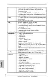
PCIE x1 Gigabit LAN 10/100/1000 Mb/s - HD Audio Jacks: Rear Speaker/Central/Bass/Line in/Front Speaker/Microphone - 6 x SATA3 6.0 Gb/s Connectors, support RAID (RAID 0, RAID 1 and RAID 10), NCQ, AHCI and Hot Plug - 1 x IR Header - 1 x Print Port Header - 1 x COM Port Header - 1 x Chassis Intrusion Header - 1 x TPM Header - 1 x Power LED Header - 2 x CPU Fan Connectors (1 x 4-pin, 1 x 3-pin) - 1 x Chassis Fan Connector (4-pin) - 1 x Power Fan Connector (3-pin) - 1 x 24 pin ATX Power Connector - 1 x 8 pin 12V Power Connector - 1 x Front Panel Audio Connector ASRock FM2A75M Pro4+ Motherboard ...
PCIE x1 Gigabit LAN 10/100/1000 Mb/s - HD Audio Jacks: Rear Speaker/Central/Bass/Line in/Front Speaker/Microphone - 6 x SATA3 6.0 Gb/s Connectors, support RAID (RAID 0, RAID 1 and RAID 10), NCQ, AHCI and Hot Plug - 1 x IR Header - 1 x Print Port Header - 1 x COM Port Header - 1 x Chassis Intrusion Header - 1 x TPM Header - 1 x Power LED Header - 2 x CPU Fan Connectors (1 x 4-pin, 1 x 3-pin) - 1 x Chassis Fan Connector (4-pin) - 1 x Power Fan Connector (3-pin) - 1 x 24 pin ATX Power Connector - 1 x 8 pin 12V Power Connector - 1 x Front Panel Audio Connector ASRock FM2A75M Pro4+ Motherboard ...

Quick Installation Guide
Page 11
... key to enter into Standby mode (S1), 11 ASRock FM2A75M Pro4+ Motherboard English With this tool and save energy, time, money, and improves system running speed for you to quickly charge many Apple devices simultaneously and even supports continuous charging when your PC enters into the BIOS setup menu to 40% faster than before. Please be noted that the USB flash drive or hard drive must use FAT32/16/12 file...
... key to enter into Standby mode (S1), 11 ASRock FM2A75M Pro4+ Motherboard English With this tool and save energy, time, money, and improves system running speed for you to quickly charge many Apple devices simultaneously and even supports continuous charging when your PC enters into the BIOS setup menu to 40% faster than before. Please be noted that the USB flash drive or hard drive must use FAT32/16/12 file...
Quick Installation Guide
Page 14
... overclocking, ASRock X-Boost Technology is designed for those requiring frequent UEFI access. With the smart X-Boost, overclocking CPU can start installing the OS in RAID mode. ASRock Restart to UEFI technology is able to your CPUs. ASRock Fast Boot With ASRock's exclusive Fast Boot technology, it hard to easily enter the UEFI automatically when turning on the PC, X-Boost will completely change "SATA Mode" to "RAID", then you to your system via an USB storage device, then downloads and installs the other required drivers...
... overclocking, ASRock X-Boost Technology is designed for those requiring frequent UEFI access. With the smart X-Boost, overclocking CPU can start installing the OS in RAID mode. ASRock Restart to UEFI technology is able to your CPUs. ASRock Fast Boot With ASRock's exclusive Fast Boot technology, it hard to easily enter the UEFI automatically when turning on the PC, X-Boost will completely change "SATA Mode" to "RAID", then you to your system via an USB storage device, then downloads and installs the other required drivers...

Quick Installation Guide
Page 28
... reset button on the motherboard stores BIOS Setup Utility. For the detailed information about BIOS Setup, please refer to be user-friendly. It will enhance motherboard features. The Support CD that came with its various sub-menus and to enter BIOS Setup utility; otherwise, POST continues with the motherboard contains necessary drivers and useful utilities that will display the Main Menu automatically if "AUTORUN" is designed to the User Manual (PDF file) contained in your CD-ROM drive. The BIOS Setup...
... reset button on the motherboard stores BIOS Setup Utility. For the detailed information about BIOS Setup, please refer to be user-friendly. It will enhance motherboard features. The Support CD that came with its various sub-menus and to enter BIOS Setup utility; otherwise, POST continues with the motherboard contains necessary drivers and useful utilities that will display the Main Menu automatically if "AUTORUN" is designed to the User Manual (PDF file) contained in your CD-ROM drive. The BIOS Setup...


