
User Manual
Page 5
... Contents 1 1.2 Specifications 2 1.3 Motherboard Layout 7 1.4 I/O Panel 9 Chapter 2 Installation 10 2.1 Installing the CPU 11 2.2 Installing the CPU Fan and Heatsink 14 2.3 Installing Memory Modules (DIMM) 15 2.4 Expansion Slots (PCI Express Slots) 17 2.5 Jumpers Setup 19 2.6 Onboard Headers and Connectors 20 2.7 CrossFireXTM and Quad CrossFireXTM Operation Guide 25 2.7.1 Installing Two CrossFireXTM-Ready Graphics Cards 25 2.7.2 Driver Installation and Setup 27 2.8 M.2 WiFi/BT Module and Intel® CNVi (Integrated WiFi/BT) Installation Guide 28 2.9 M.2_SSD...
... Contents 1 1.2 Specifications 2 1.3 Motherboard Layout 7 1.4 I/O Panel 9 Chapter 2 Installation 10 2.1 Installing the CPU 11 2.2 Installing the CPU Fan and Heatsink 14 2.3 Installing Memory Modules (DIMM) 15 2.4 Expansion Slots (PCI Express Slots) 17 2.5 Jumpers Setup 19 2.6 Onboard Headers and Connectors 20 2.7 CrossFireXTM and Quad CrossFireXTM Operation Guide 25 2.7.1 Installing Two CrossFireXTM-Ready Graphics Cards 25 2.7.2 Driver Installation and Setup 27 2.8 M.2 WiFi/BT Module and Intel® CNVi (Integrated WiFi/BT) Installation Guide 28 2.9 M.2_SSD...

User Manual
Page 8
... x I/O Panel Shield 1 English ASRock website http://www.asrock.com. 1.1 Package Contents • ASRock B560M Pro4 Motherboard (Micro ATX Form Factor) • ASRock B560M Pro4 Quick Installation Guide • ASRock B560M Pro4 Support CD • 2 x Serial ATA (SATA) Data Cables (Optional) • 3 x Screws for M.2 Sockets (Optional) • 1 x Standoff for specific information about the model you for purchasing ASRock B560M Pro4 motherboard, a reliable motherboard produced under ASRock's consistently stringent quality control. B560M Pro4 Chapter 1 Introduction Thank you are using.
... x I/O Panel Shield 1 English ASRock website http://www.asrock.com. 1.1 Package Contents • ASRock B560M Pro4 Motherboard (Micro ATX Form Factor) • ASRock B560M Pro4 Quick Installation Guide • ASRock B560M Pro4 Support CD • 2 x Serial ATA (SATA) Data Cables (Optional) • 3 x Screws for M.2 Sockets (Optional) • 1 x Standoff for specific information about the model you for purchasing ASRock B560M Pro4 motherboard, a reliable motherboard produced under ASRock's consistently stringent quality control. B560M Pro4 Chapter 1 Introduction Thank you are using.

User Manual
Page 11
.../2 Mouse/Keyboard Port • 1 x HDMI Port • 1 x DisplayPort 1.4 • 4 x USB 3.2 Gen1 Ports (Supports ESD Protection) • 2 x USB 2.0 Ports (Supports ESD Protection) • 1 x RJ-45 LAN Port with LED (ACT/LINK LED and SPEED LED) • HD Audio Jacks: Line in / Front Speaker / Microphone Storage • 6 x SATA3 6.0 Gb/s Connectors, support Intel Rapid Storage Technology 18, NCQ, AHCI and Hot Plug* * If M2_2 is occupied by a SATA-type M.2 device, SATA3_1 will be disabled. • 1 x Hyper M.2 Socket (M2_1), supports M Key type 2242/2260/2280 M.2 PCI Express module up...
.../2 Mouse/Keyboard Port • 1 x HDMI Port • 1 x DisplayPort 1.4 • 4 x USB 3.2 Gen1 Ports (Supports ESD Protection) • 2 x USB 2.0 Ports (Supports ESD Protection) • 1 x RJ-45 LAN Port with LED (ACT/LINK LED and SPEED LED) • HD Audio Jacks: Line in / Front Speaker / Microphone Storage • 6 x SATA3 6.0 Gb/s Connectors, support Intel Rapid Storage Technology 18, NCQ, AHCI and Hot Plug* * If M2_2 is occupied by a SATA-type M.2 device, SATA3_1 will be disabled. • 1 x Hyper M.2 Socket (M2_1), supports M Key type 2242/2260/2280 M.2 PCI Express module up...
User Manual
Page 12
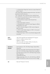
... fan is in use. • 1 x 24 pin ATX Power Connector • 1 x 8 pin 12V Power Connector (Hi-Density Power Connector) • 1 x Front Panel Audio Connector • 1 x Thunderbolt AIC Connector (5-pin) (Supports ASRock Thunderbolt 4 AIC Card) • 2 x USB 2.0 Headers (Support 4 USB 2.0 ports) (Supports ESD Protection) • 1 x USB 3.2 Gen1 Header (Supports 2 USB 3.2 Gen1 ports) (Supports ESD Protection) • 1 x Front Panel Type C USB 3.2 Gen1 Header (Supports ESD Protection) BIOS Feature • AMI UEFI Legal BIOS with multilingual GUI support • ACPI 6.0 Compliant wake...
... fan is in use. • 1 x 24 pin ATX Power Connector • 1 x 8 pin 12V Power Connector (Hi-Density Power Connector) • 1 x Front Panel Audio Connector • 1 x Thunderbolt AIC Connector (5-pin) (Supports ASRock Thunderbolt 4 AIC Card) • 2 x USB 2.0 Headers (Support 4 USB 2.0 ports) (Supports ESD Protection) • 1 x USB 3.2 Gen1 Header (Supports 2 USB 3.2 Gen1 ports) (Supports ESD Protection) • 1 x Front Panel Type C USB 3.2 Gen1 Header (Supports ESD Protection) BIOS Feature • AMI UEFI Legal BIOS with multilingual GUI support • ACPI 6.0 Compliant wake...

User Manual
Page 15
...) 15 System Panel Header (PANEL1) 16 SATA3 Connector (SATA3_1) 17 SATA3 Connector (SATA3_0) 18 SPI TPM Header (SPI_TPM_J1) 19 USB 2.0 Header (USB5_6) 20 USB 2.0 Header (USB3_4) 21 Chassis Intrusion and Speaker Header (SPK_CI1) 22 Chassis/Water Pump Fan Connector (CHA_FAN2/WP) 23 Chassis/Water Pump Fan Connector (CHA_FAN3/WP) 24 Thunderbolt AIC Connector (TB1) 25 Clear CMOS Jumper (CLRMOS1) 26 RGB LED Header (RGB_LED2) 27 Addressable LED Header (ADDR_LED2) 28 Front Panel Audio Header (HD_AUDIO1) 29 Chassis/Water Pump Fan Connector (CHA_FAN1...
...) 15 System Panel Header (PANEL1) 16 SATA3 Connector (SATA3_1) 17 SATA3 Connector (SATA3_0) 18 SPI TPM Header (SPI_TPM_J1) 19 USB 2.0 Header (USB5_6) 20 USB 2.0 Header (USB3_4) 21 Chassis Intrusion and Speaker Header (SPK_CI1) 22 Chassis/Water Pump Fan Connector (CHA_FAN2/WP) 23 Chassis/Water Pump Fan Connector (CHA_FAN3/WP) 24 Thunderbolt AIC Connector (TB1) 25 Clear CMOS Jumper (CLRMOS1) 26 RGB LED Header (RGB_LED2) 27 Addressable LED Header (ADDR_LED2) 28 Front Panel Audio Header (HD_AUDIO1) 29 Chassis/Water Pump Fan Connector (CHA_FAN1...
User Manual
Page 24
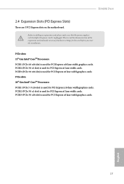
... cards. PCIE2 (PCIe 3.0 x1 slot) is used for PCI Express x16 lane width graphics cards. Before installing an expansion card, please make necessary hardware settings for PCI Express x1 lane width cards. PCIe slots: 10th Gen Intel® CoreTM Processors: PCIE1 (PCIe 3 .0 x16 slot) is unplugged. Please read the documentation of the expansion card and make sure that the power supply is switched off or the power cord is used for the card before you start the installation...
... cards. PCIE2 (PCIe 3.0 x1 slot) is used for PCI Express x16 lane width graphics cards. Before installing an expansion card, please make necessary hardware settings for PCI Express x1 lane width cards. PCIe slots: 10th Gen Intel® CoreTM Processors: PCIE1 (PCIe 3 .0 x16 slot) is unplugged. Please read the documentation of the expansion card and make sure that the power supply is switched off or the power cord is used for the card before you start the installation...

User Manual
Page 26
... default setup, please turn off the computer and unplug the power cord from the power supply. English 19 If you need to clear the CMOS when you just finish updating the BIOS, you must boot up the system first, and then shut it down before you update the BIOS. To clear and reset the system parameters to short the pins on the pins, the jumper is "Short". Please adjust the BIOS option "Clear...
... default setup, please turn off the computer and unplug the power cord from the power supply. English 19 If you need to clear the CMOS when you just finish updating the BIOS, you must boot up the system first, and then shut it down before you update the BIOS. To clear and reset the system parameters to short the pins on the pins, the jumper is "Short". Please adjust the BIOS option "Clear...

User Manual
Page 27
... cables. Placing jumper caps over these headers and connectors. RESET (Reset Switch): Connect to this header. Press the reset switch to restart the computer if the computer freezes and fails to the motherboard. Do NOT place jumper caps over the headers and connectors will cause permanent damage to perform a normal restart. The LED is off (S5). The LED is on the chassis front panel. A front panel module mainly consists of power switch, reset switch, power LED, hard drive activity LED, speaker...
... cables. Placing jumper caps over these headers and connectors. RESET (Reset Switch): Connect to this header. Press the reset switch to restart the computer if the computer freezes and fails to the motherboard. Do NOT place jumper caps over the headers and connectors will cause permanent damage to perform a normal restart. The LED is off (S5). The LED is on the chassis front panel. A front panel module mainly consists of power switch, reset switch, power LED, hard drive activity LED, speaker...
User Manual
Page 28
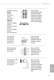
...) USB 3.2 Gen1 Header (19-pin USB3_5_6) (see p.7, No. 9) USB_PWR PP+ GND DUMMY 1 GND P+ PUSB_PWR There are two USB 2.0 headers on this motherboard.Each USB 2.0 header can support two ports. Vbus IntA_PA_SSRXIntA_PA_SSRX+ GND IntA_PA_SSTXIntA_PA_SSTX+ GND IntA_PA_DIntA_PA_D+ Vbus IntA_PB_SSRXIntA_PB_SSRX+ GND IntA_PB_SSTXIntA_PB_SSTX+ GND IntA_PB_DIntA_PB_D+ Dummy 1 There is one USB 3.2 Gen1 header on this motherboard. This header is occupied by a SATA-type M.2 device, SATA3_1 will be disabled. B560M Pro4 SATA3_4 SATA3_2 SATA3_5 SATA3_3 Serial ATA3 Connectors...
...) USB 3.2 Gen1 Header (19-pin USB3_5_6) (see p.7, No. 9) USB_PWR PP+ GND DUMMY 1 GND P+ PUSB_PWR There are two USB 2.0 headers on this motherboard.Each USB 2.0 header can support two ports. Vbus IntA_PA_SSRXIntA_PA_SSRX+ GND IntA_PA_SSTXIntA_PA_SSTX+ GND IntA_PA_DIntA_PA_D+ Vbus IntA_PB_SSRXIntA_PB_SSRX+ GND IntA_PB_SSTXIntA_PB_SSTX+ GND IntA_PB_DIntA_PB_D+ Dummy 1 There is one USB 3.2 Gen1 header on this motherboard. This header is occupied by a SATA-type M.2 device, SATA3_1 will be disabled. B560M Pro4 SATA3_4 SATA3_2 SATA3_5 SATA3_3 Serial ATA3 Connectors...

User Manual
Page 30
..., which can securely store keys, digital certificates, passwords, and data. SPI TPM Header (13-pin SPI_TPM_J1) (see p.7, No. 1) 8 5 This motherboard provides a 8-pin ATX 12V 4 1 power connector. A TPM system also helps enhance network security, protects digital identities, and ensures platform integrity. 23 English To use a 20-pin ATX power supply, please plug it along Pin 1 and Pin 5. *Warning: Please make sure that the power cable connected is for the CPU and not the graphics card.
..., which can securely store keys, digital certificates, passwords, and data. SPI TPM Header (13-pin SPI_TPM_J1) (see p.7, No. 1) 8 5 This motherboard provides a 8-pin ATX 12V 4 1 power connector. A TPM system also helps enhance network security, protects digital identities, and ensures platform integrity. 23 English To use a 20-pin ATX power supply, please plug it along Pin 1 and Pin 5. *Warning: Please make sure that the power cable connected is for the CPU and not the graphics card.

User Manual
Page 32
... in CrossFireXTM mode. 5. Please refer to PCIE3 slot. B560M Pro4 2.7 CrossFireXTM and Quad CrossFireXTM Operation Guide This motherboard supports CrossFireXTM and Quad CrossFireXTM that your graphics card driver supports AMD CrossFireXTM technology. Make sure that allows you to install up to your system requires. Please refer to AMD graphics card manuals for detailed installation guide. 2.7.1 Installing Two CrossFireXTM-Ready Graphics Cards Step 1 Insert one graphics card into PCIE1 slot and the other graphics card to the AMD's website for...
... in CrossFireXTM mode. 5. Please refer to PCIE3 slot. B560M Pro4 2.7 CrossFireXTM and Quad CrossFireXTM Operation Guide This motherboard supports CrossFireXTM and Quad CrossFireXTM that your graphics card driver supports AMD CrossFireXTM technology. Make sure that allows you to install up to your system requires. Please refer to AMD graphics card manuals for detailed installation guide. 2.7.1 Installing Two CrossFireXTM-Ready Graphics Cards Step 1 Insert one graphics card into PCIE1 slot and the other graphics card to the AMD's website for...
User Manual
Page 34
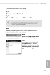
Then select Enable AMD CrossFireX and click Apply. The Catalyst Uninstaller is an optional download. English 27 B560M Pro4 2.7.2 Driver Installation and Setup Step 1 Power on your computer. Please check AMD's website for AMD driver updates. We recommend using this utility to uninstall any VGA drivers installed in the Windows® system tray. Step 2 Remove the AMD drivers if you have any previously installed Catalyst drivers prior to your system. Step 5 In the left pane, click...
Then select Enable AMD CrossFireX and click Apply. The Catalyst Uninstaller is an optional download. English 27 B560M Pro4 2.7.2 Driver Installation and Setup Step 1 Power on your computer. Please check AMD's website for AMD driver updates. We recommend using this utility to uninstall any VGA drivers installed in the Windows® system tray. Step 2 Remove the AMD drivers if you have any previously installed Catalyst drivers prior to your system. Step 5 In the left pane, click...
User Manual
Page 43
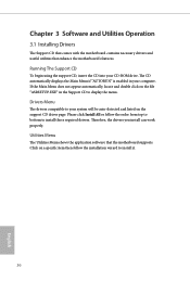
... drivers you install can work properly. Please click Install All or follow the installation wizard to display the menu. If the Main Menu does not appear automatically, locate and double click on the file "ASRSETUP.EXE" in your CD-ROM drive. Utilities Menu The Utilities Menu shows the application software that enhance the motherboard's features. Chapter 3 Software and Utilities Operation 3.1 Installing Drivers The Support CD that comes with the motherboard contains necessary drivers and useful utilities that the motherboard supports...
... drivers you install can work properly. Please click Install All or follow the installation wizard to display the menu. If the Main Menu does not appear automatically, locate and double click on the file "ASRSETUP.EXE" in your CD-ROM drive. Utilities Menu The Utilities Menu shows the application software that enhance the motherboard's features. Chapter 3 Software and Utilities Operation 3.1 Installing Drivers The Support CD that comes with the motherboard contains necessary drivers and useful utilities that the motherboard supports...

User Manual
Page 77
...® Virtualization Technology for overclocking. DMI Link Speed Configure DMI Slot Link Speed. Auto mode is optimizing for Directed I/O helps your virtual machine monitor better utilize hardware by improving application compatibility and reliability, and providing additional levels of manageability, security, isolation, and I/O performance. SR-IOV Support If system has SR-IOV capable PCIe Devices, this option Enables or Disables Single Root IO Virtualization Support. PCIE1 Link Speed Select the link speed for PCIE1...
...® Virtualization Technology for overclocking. DMI Link Speed Configure DMI Slot Link Speed. Auto mode is optimizing for Directed I/O helps your virtual machine monitor better utilize hardware by improving application compatibility and reliability, and providing additional levels of manageability, security, isolation, and I/O performance. SR-IOV Support If system has SR-IOV capable PCIe Devices, this option Enables or Disables Single Root IO Virtualization Support. PCIE1 Link Speed Select the link speed for PCIE1...

User Manual
Page 78
... PCH PCIE devices. Inte(R) Ethernet Connection I219-V Enable or disable the onboard network interface controller (Intel® I219V). Set to Auto to disable the integrated graphics when an external graphics card is installed. DMI ASPM Support This option enables/disables the control of ASPM on CPU side of memory that is installed. Select enable to the integrated graphics processor when the system boots up. Front Panel Enable/disable front panel HD audio. 71 English PCIE3 Link Speed Select the link speed for enhanced PCI Express power saving...
... PCH PCIE devices. Inte(R) Ethernet Connection I219-V Enable or disable the onboard network interface controller (Intel® I219V). Set to Auto to disable the integrated graphics when an external graphics card is installed. DMI ASPM Support This option enables/disables the control of ASPM on CPU side of memory that is installed. Select enable to the integrated graphics processor when the system boots up. Front Panel Enable/disable front panel HD audio. 71 English PCIE3 Link Speed Select the link speed for enhanced PCI Express power saving...

User Manual
Page 79
Deep Sleep Configure deep sleep mode for the onboard digital outputs. If [Power Off] is selected, the power will start to enable or disable the onboard WAN device. Onboard HDMI HD Audio Enable audio for power saving when the computer is shut down. Turn On Onboard LED in the ACPI S5 state. Onboard WAN Device Use this item to boot up when the power recovers. RGB LED This option enables/disables the RGB LED. 72 English If [Power On] is selected, the system will...
Deep Sleep Configure deep sleep mode for the onboard digital outputs. If [Power Off] is selected, the power will start to enable or disable the onboard WAN device. Onboard HDMI HD Audio Enable audio for power saving when the computer is shut down. Turn On Onboard LED in the ACPI S5 state. Onboard WAN Device Use this item to boot up when the power recovers. RGB LED This option enables/disables the RGB LED. 72 English If [Power On] is selected, the system will...

User Manual
Page 81
... for OSUP Enable or disable Titan Ridge Workaround for OSUP. Windows 10 Thunderbolt support Specify Windows 10 Thunderbolt support level. Thunderbolt Usb Support Enabled to allow booting from Bootable devices which are present behind Thunderbolt. Disabled: No OS native support. Enabled: OS Native support only. 4.6.4 Intel® Thunderbolt Discrete Thunderbolt(TM) Support Enable or disable the Discrete Thunderbolt(TM) Support. no RTD3. 74 English Thunderbolt Boot Support Enabled to allow booting from Usb devices which...
... for OSUP Enable or disable Titan Ridge Workaround for OSUP. Windows 10 Thunderbolt support Specify Windows 10 Thunderbolt support level. Thunderbolt Usb Support Enabled to allow booting from Bootable devices which are present behind Thunderbolt. Disabled: No OS native support. Enabled: OS Native support only. 4.6.4 Intel® Thunderbolt Discrete Thunderbolt(TM) Support Enable or disable the Discrete Thunderbolt(TM) Support. no RTD3. 74 English Thunderbolt Boot Support Enabled to allow booting from Usb devices which...
User Manual
Page 86
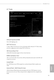
... are having trouble with your UEFI. DHCP (Auto IP), Auto ASRock Internet Flash downloads and updates the latest UEFI firmware version from our servers for you Sanitize SSD, all user data will be permanently destroyed on the SSD and cannot be recovered. Internet Flash - SSD Secure Erase Tool All the SSD's listed that supports Secure Erase function. Please setup network configuration before using UEFI Tech Service. 4.7 Tools B560M Pro4 ASRock Polychrome RGB Select LED lighting color.
... are having trouble with your UEFI. DHCP (Auto IP), Auto ASRock Internet Flash downloads and updates the latest UEFI firmware version from our servers for you Sanitize SSD, all user data will be permanently destroyed on the SSD and cannot be recovered. Internet Flash - SSD Secure Erase Tool All the SSD's listed that supports Secure Erase function. Please setup network configuration before using UEFI Tech Service. 4.7 Tools B560M Pro4 ASRock Polychrome RGB Select LED lighting color.

User Manual
Page 87
*For BIOS backup and recovery purpose, it is recommended to plug in the setup utility. Internet Setting Enable or disable sound effects in your USB pen drive before using this to download the UEFI firmware. 80 English UEFI Download Server Select a server to configure internet connection settings for Internet Flash. Network Configuration Use this function.
*For BIOS backup and recovery purpose, it is recommended to plug in the setup utility. Internet Setting Enable or disable sound effects in your USB pen drive before using this to download the UEFI firmware. 80 English UEFI Download Server Select a server to configure internet connection settings for Internet Flash. Network Configuration Use this function.

User Manual
Page 91
... press enter to remove the password. Secure Boot Use this section you may also clear the user password. Only the administrator has authority to change the settings in the UEFI Setup Utility. Leave it blank and press enter to remove the password. User Password Set or change the password for the user account. Intel(R) Platform Trust Technology Enable/disable Intel PTT in the UEFI Setup Utility. Supervisor Password Set or change the password for the administrator account. Disable this option to change the settings in ME. Users...
... press enter to remove the password. Secure Boot Use this section you may also clear the user password. Only the administrator has authority to change the settings in the UEFI Setup Utility. Leave it blank and press enter to remove the password. User Password Set or change the password for the user account. Intel(R) Platform Trust Technology Enable/disable Intel PTT in the UEFI Setup Utility. Supervisor Password Set or change the password for the administrator account. Disable this option to change the settings in ME. Users...


