

User Manual
Page 4
UEFI SETUP UTILITY 36 4.1 Introduction 36 Installation 11 2.1 CPU Installation 12 2.2 Installation of CPU Fan and Heatsink 13 2.3 Installation of Memory Modules (DIMM) 14 2.4 Expansion Slot (PCI Express Slot) 16 2.5 Jumpers Setup 17 2.6 Onboard Headers and Connectors 18 2.7 AMD Dual Graphics Operation Guide 22 2.8 M.2_SSD (NGFF) Module Installation Guide 24 3. Introduction 1 1.1 Package Contents 1 1.2 Specifications 2 1.3 Motherboard Layout 6 1.4 I/O Panel 8 1.5 WiFi-802.11ac Module and ASRock WiFi 2.4/5 GHz Antenna 10 2. Software and Utilities Operation...
UEFI SETUP UTILITY 36 4.1 Introduction 36 Installation 11 2.1 CPU Installation 12 2.2 Installation of CPU Fan and Heatsink 13 2.3 Installation of Memory Modules (DIMM) 14 2.4 Expansion Slot (PCI Express Slot) 16 2.5 Jumpers Setup 17 2.6 Onboard Headers and Connectors 18 2.7 AMD Dual Graphics Operation Guide 22 2.8 M.2_SSD (NGFF) Module Installation Guide 24 3. Introduction 1 1.1 Package Contents 1 1.2 Specifications 2 1.3 Motherboard Layout 6 1.4 I/O Panel 8 1.5 WiFi-802.11ac Module and ASRock WiFi 2.4/5 GHz Antenna 10 2. Software and Utilities Operation...
User Manual
Page 6
... ASRock's consistently stringent quality control. www.asrock.com/support/index.asp 1.1 Package Contents ASRock A88M-ITX/ac R2.0 Motherboard (Mini-ITX Form Factor) ASRock A88M-ITX/ac R2.0 Quick Installation Guide ASRock A88M-ITX/ac R2.0 Support CD 2 x Serial ATA (SATA) Data Cables (Optional) 1 x I/O Panel Shield 2 x SMA WiFi Antenna Cables 2 x ASRock WiFi 2.4/5 GHz Antennas 1 English In case any modifications of the software and utilities. ASRock website http://www.asrock.com If you are using. Introduction Thank you for specific information about the model you require technical support...
... ASRock's consistently stringent quality control. www.asrock.com/support/index.asp 1.1 Package Contents ASRock A88M-ITX/ac R2.0 Motherboard (Mini-ITX Form Factor) ASRock A88M-ITX/ac R2.0 Quick Installation Guide ASRock A88M-ITX/ac R2.0 Support CD 2 x Serial ATA (SATA) Data Cables (Optional) 1 x I/O Panel Shield 2 x SMA WiFi Antenna Cables 2 x ASRock WiFi 2.4/5 GHz Antennas 1 English In case any modifications of the software and utilities. ASRock website http://www.asrock.com If you are using. Introduction Thank you for specific information about the model you require technical support...
User Manual
Page 8
A88M-ITX/ac R2.0 • Supports Auto Lip Sync, Deep Color (12bpc), xvYCC and HBR (High Bit Rate Audio) with HDMI Port (Compliant HDMI monitor is required) • Supports Blu-ray Stereoscopic 3D with HDMI Port • Supports AMD Steady VideoTM 2.0: New video post processing capability for automatic jitter reduction on home/online video • Supports HDCP with DVI-D and HDMI Ports • Supports Full HD 1080p Blu-ray (BD) playback with DVI-D and HDMI Ports Audio • 7.1 CH...
A88M-ITX/ac R2.0 • Supports Auto Lip Sync, Deep Color (12bpc), xvYCC and HBR (High Bit Rate Audio) with HDMI Port (Compliant HDMI monitor is required) • Supports Blu-ray Stereoscopic 3D with HDMI Port • Supports AMD Steady VideoTM 2.0: New video post processing capability for automatic jitter reduction on home/online video • Supports HDCP with DVI-D and HDMI Ports • Supports Full HD 1080p Blu-ray (BD) playback with DVI-D and HDMI Ports Audio • 7.1 CH...

User Manual
Page 9
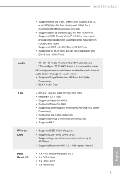
... (ASRock Full Spike Protection)) BIOS Feature • AMI UEFI Legal BIOS with LED (ACT/LINK LED and SPEED LED) • HD Audio Jacks: Line in / Front Speaker / Microphone Storage • 6 x SATA3 6.0 Gb/s Connectors, support RAID (RAID 0, RAID 1, RAID 5 and RAID 10), NCQ, AHCI and Hot Plug • 1 x M.2 Socket (Key E), supports type 2230 WiFi/BT module Connector • 1 x Chassis Intrusion Header • 1 x CPU Fan Connector (4-pin) • 1 x Chassis Fan Connector (4-pin) * CPU_FAN1 and CHA_FAN1 can auto detect if 3-pin or 4-pin fan is in use. • 1 x 24 pin ATX Power...
... (ASRock Full Spike Protection)) BIOS Feature • AMI UEFI Legal BIOS with LED (ACT/LINK LED and SPEED LED) • HD Audio Jacks: Line in / Front Speaker / Microphone Storage • 6 x SATA3 6.0 Gb/s Connectors, support RAID (RAID 0, RAID 1, RAID 5 and RAID 10), NCQ, AHCI and Hot Plug • 1 x M.2 Socket (Key E), supports type 2230 WiFi/BT module Connector • 1 x Chassis Intrusion Header • 1 x CPU Fan Connector (4-pin) • 1 x Chassis Fan Connector (4-pin) * CPU_FAN1 and CHA_FAN1 can auto detect if 3-pin or 4-pin fan is in use. • 1 x 24 pin ATX Power...
User Manual
Page 10
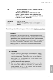
... processor supports Windows® 10 64-bit/ 8.1 64-bit / 7 32-bit / 7 64-bit only. Whether 2400/2133/1866/1600MHz memory speed is re- ASRock website http://www.asrock.com 2. English 5 For Windows® 64-bit OS with overclocking, including adjusting the setting in the BIOS, applying Untied Overclocking Technology, or using third-party overclocking tools. If you adopt. A88M-ITX/ac R2.0 OS • Microsoft® Windows® 10 32-bit / 10 64-bit / 8.1 32-bit / 8.1 64-bit / 7 32-bit...
... processor supports Windows® 10 64-bit/ 8.1 64-bit / 7 32-bit / 7 64-bit only. Whether 2400/2133/1866/1600MHz memory speed is re- ASRock website http://www.asrock.com 2. English 5 For Windows® 64-bit OS with overclocking, including adjusting the setting in the BIOS, applying Untied Overclocking Technology, or using third-party overclocking tools. If you adopt. A88M-ITX/ac R2.0 OS • Microsoft® Windows® 10 32-bit / 10 64-bit / 8.1 32-bit / 8.1 64-bit / 7 32-bit...

User Manual
Page 16
... configuration of the following precautions before you install motherboard components or change any component, ensure that the motherboard fits into the screw holes to secure the motherboard to the motherboard, peripherals, and/or components. 1. Also remember to use a grounded wrist strap or touch a safety grounded object before you handle components. 3. A88M-ITX/ac R2.0 2. Doing so may cause severe damage to the chassis...
... configuration of the following precautions before you install motherboard components or change any component, ensure that the motherboard fits into the screw holes to secure the motherboard to the motherboard, peripherals, and/or components. 1. Also remember to use a grounded wrist strap or touch a safety grounded object before you handle components. 3. A88M-ITX/ac R2.0 2. Doing so may cause severe damage to the chassis...
User Manual
Page 22
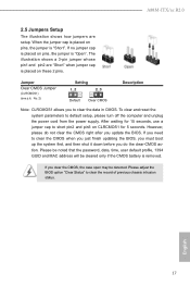
... password, date, time, user default profile, 1394 GUID and MAC address will be detected. If you to clear the record of previous chassis intrusion status. If no jumper cap is placed on pins, the jumper is "Open". After waiting for 15 seconds, use a jumper cap to default setup, please turn off the computer and unplug the power cord from the power supply. However, please do the clear-CMOS ac- Jumper Setting Description Clear CMOS Jumper...
... password, date, time, user default profile, 1394 GUID and MAC address will be detected. If you to clear the record of previous chassis intrusion status. If no jumper cap is placed on pins, the jumper is "Open". After waiting for 15 seconds, use a jumper cap to default setup, please turn off the computer and unplug the power cord from the power supply. However, please do the clear-CMOS ac- Jumper Setting Description Clear CMOS Jumper...

User Manual
Page 24
... for AC'97 audio panel. You don't need to the reset switch on the chassis front panel. PWRBTN (Power Switch): Connect to the pin assignments below : A. High Definition Audio supports Jack Sensing, but the panel wire on the chassis to this header according to the power switch on the chassis front panel. Connect the power switch, reset switch and system status indicator on the chassis must support HDA to install your system using the power switch. Note the positive and negative pins before connecting the cables...
... for AC'97 audio panel. You don't need to the reset switch on the chassis front panel. PWRBTN (Power Switch): Connect to the pin assignments below : A. High Definition Audio supports Jack Sensing, but the panel wire on the chassis to this header according to the power switch on the chassis front panel. Connect the power switch, reset switch and system status indicator on the chassis must support HDA to install your system using the power switch. Note the positive and negative pins before connecting the cables...

User Manual
Page 26
To use the 20-pin ATX power supply, please plug your power supply along with Pin 1 and Pin 13. 24 13 20-Pin ATX Power Supply Installation 12 1 ATX 12V Power Connector 1 (8-pin ATX12V1) (see p.6 No. 1) 1 GND Signal This motherboard supports CASE OPEN detection feature that detects if the chassis cover has been removed. A88M-ITX/ac R2.0 ATX Power Connector 24 (24-pin ATXPWR1) (see p.6 No. 4) 12 13 Please connect an ATX power supply to this connector. 8 Though this motherboard provides 24-pin ATX power connector, it can still work if you ...
To use the 20-pin ATX power supply, please plug your power supply along with Pin 1 and Pin 13. 24 13 20-Pin ATX Power Supply Installation 12 1 ATX 12V Power Connector 1 (8-pin ATX12V1) (see p.6 No. 1) 1 GND Signal This motherboard supports CASE OPEN detection feature that detects if the chassis cover has been removed. A88M-ITX/ac R2.0 ATX Power Connector 24 (24-pin ATXPWR1) (see p.6 No. 4) 12 13 Please connect an ATX power supply to this connector. 8 Though this motherboard provides 24-pin ATX power connector, it can still work if you ...

User Manual
Page 27
... information. Please keep the default UEFI setting of AMD Dual Graphics Step 1. Boot into OS. Currently, AMD Dual Graphics Technology is only supported with combined output to your system for blisteringly-fast frame rates. Install the onboard VGA driver from onboard display only. Step 2. Step 5. Right-click the desktop. Install one AMD RADEON PCI Express graphics card to enter AMD VISION Engine Control Center. 22 English Connect the monitor cable to operate simultaneously with Windows® 10 / 8.1 / 7 OS. AMD Dual Graphics brings multi-GPU performance...
... information. Please keep the default UEFI setting of AMD Dual Graphics Step 1. Boot into OS. Currently, AMD Dual Graphics Technology is only supported with combined output to your system for blisteringly-fast frame rates. Install the onboard VGA driver from onboard display only. Step 2. Step 5. Right-click the desktop. Install one AMD RADEON PCI Express graphics card to enter AMD VISION Engine Control Center. 22 English Connect the monitor cable to operate simultaneously with Windows® 10 / 8.1 / 7 OS. AMD Dual Graphics brings multi-GPU performance...
User Manual
Page 30
... computer. Therefore, the drivers you install can work properly. A88M-ITX/ac R2.0 3. Please click Install All or follow the installation wizard to install those required drivers. Drivers Menu The drivers compatible to your system will be auto-detected and listed on the file "ASRSETUP.EXE" in your CD-ROM drive. If the Main Menu does not appear automatically, locate and double click on the support CD driver page. Click on a specific item then follow the...
... computer. Therefore, the drivers you install can work properly. A88M-ITX/ac R2.0 3. Please click Install All or follow the installation wizard to install those required drivers. Drivers Menu The drivers compatible to your system will be auto-detected and listed on the file "ASRSETUP.EXE" in your CD-ROM drive. If the Main Menu does not appear automatically, locate and double click on the support CD driver page. Click on a specific item then follow the...

User Manual
Page 41
... the UEFI software is a blend of the screen has a menu bar with the following UEFI setup screens and descriptions are for reference purpose only, and they may run the UEFI SETUP UTILITY when you see on the system chassis. UEFI SETUP UTILITY 4.1 Introduction ASRock Interactive UEFI is constantly being updated, the following selections: Main For setting system time/date information OC Tweaker For overclocking configurations Advanced For advanced system configurations Tool Useful tools H/W Monitor Displays...
... the UEFI software is a blend of the screen has a menu bar with the following UEFI setup screens and descriptions are for reference purpose only, and they may run the UEFI SETUP UTILITY when you see on the system chassis. UEFI SETUP UTILITY 4.1 Introduction ASRock Interactive UEFI is constantly being updated, the following selections: Main For setting system time/date information OC Tweaker For overclocking configurations Advanced For advanced system configurations Tool Useful tools H/W Monitor Displays...

User Manual
Page 43
... OC Mode You can set the item "Overclock Mode" to [Manual]. If [Enabled] is selected, the power consumption is [Enabled]. APU/PCIE Frequency (MHz) This item appears only when you adopt supports this to select enable or disable AMD Turbo Core Technology. Please be [Auto] for the CPU mode being used. The default value is reduced when overclocking. 38 English 4.3 OC Tweaker Screen In the OC Tweaker screen, you can use DVI or HDMI monitor to get...
... OC Mode You can set the item "Overclock Mode" to [Manual]. If [Enabled] is selected, the power consumption is [Enabled]. APU/PCIE Frequency (MHz) This item appears only when you adopt supports this to select enable or disable AMD Turbo Core Technology. Please be [Auto] for the CPU mode being used. The default value is reduced when overclocking. 38 English 4.3 OC Tweaker Screen In the OC Tweaker screen, you can use DVI or HDMI monitor to get...

User Manual
Page 45
... the same node, or accross nodes, decreasing access contention. The default value is [Auto]. 40 English SB Voltage Use this item to view SPD data. DRAM Timing Control DRAM Slot Use this to select SB Voltage. Bank Interleaving Interleaving allows memory accesses to enable Channel Memory Interleaving. Voltage Configuration DRAM Voltage Use this to select DRAM Voltage. APU PCIE Voltage VDDP Use this to select APU PCIE Voltage VDDP. The default value is [Auto]. The default value is [Auto]. The default value is [Auto]. Configuration options: [Disabled], [Auto].
... the same node, or accross nodes, decreasing access contention. The default value is [Auto]. 40 English SB Voltage Use this item to view SPD data. DRAM Timing Control DRAM Slot Use this to select SB Voltage. Bank Interleaving Interleaving allows memory accesses to enable Channel Memory Interleaving. Voltage Configuration DRAM Voltage Use this to select DRAM Voltage. APU PCIE Voltage VDDP Use this to select APU PCIE Voltage VDDP. The default value is [Auto]. The default value is [Auto]. The default value is [Auto]. Configuration options: [Disabled], [Auto].

User Manual
Page 48
... video controllers. The default value is [PCI Express]. If you select [as HDMI]. Primary Graphics Adapter This item allows you to set the share memory feature. Onboard Graphics Select Enable/Disable/Auto for the onboard graphics. Configuration options: [Auto], [32MB], [64MB], [128MB], [256MB] [512MB], [1GB] and [2GB]. Onboard HDMI HD Audio This allows you to enable or disable IOMMU support. Configuration options: [as Dual Link DVI] and [as Dual Link DVI], you can use Dual Link DVI monitor without audio function. 4.4.2 North Bridge Configuration A88M-ITX/ac R2...
... video controllers. The default value is [PCI Express]. If you select [as HDMI]. Primary Graphics Adapter This item allows you to set the share memory feature. Onboard Graphics Select Enable/Disable/Auto for the onboard graphics. Configuration options: [Auto], [32MB], [64MB], [128MB], [256MB] [512MB], [1GB] and [2GB]. Onboard HDMI HD Audio This allows you to enable or disable IOMMU support. Configuration options: [as Dual Link DVI] and [as Dual Link DVI], you can use Dual Link DVI monitor without audio function. 4.4.2 North Bridge Configuration A88M-ITX/ac R2...

User Manual
Page 50
...ports, please disable this item to RAID mode, it is suggested to enable or disable the "SATA Controller" feature. Use this item to enable or disable the S.M.A.R.T. (Self-Monitoring, Analysis, and Reporting Technology) feature. Use this item to enable or disable SATA IDE combined mode. The default value is for SATA3_5 and SATA3_6. Configuration options: [Disabled], [Auto], [Enabled]. 45 English SATA IDE Combined Mode This item is [Enabled]. 4.4.4 Storage Configuration A88M-ITX/ac R2.0 SATA Controller Use this option is [AHCI Mode]. The default value of this item to enable...
...ports, please disable this item to RAID mode, it is suggested to enable or disable the "SATA Controller" feature. Use this item to enable or disable the S.M.A.R.T. (Self-Monitoring, Analysis, and Reporting Technology) feature. Use this item to enable or disable SATA IDE combined mode. The default value is for SATA3_5 and SATA3_6. Configuration options: [Disabled], [Auto], [Enabled]. 45 English SATA IDE Combined Mode This item is [Enabled]. 4.4.4 Storage Configuration A88M-ITX/ac R2.0 SATA Controller Use this option is [AHCI Mode]. The default value of this item to enable...

User Manual
Page 51
... AC/power remains off mode. PS/2 Keyboard Power On Use this item to enable or disable PCI devices to turn on the system from the power-soft-off when the power recovers. Check Ready Bit Enable to enter the operating system after an unexpected AC/power loss. Deep Sleep Configure deep sleep mode for better system compatibility and stability. RTC Alarm Power On Use this is ready, this item to enable or disable RTC (Real Time Clock) to power...
... AC/power remains off mode. PS/2 Keyboard Power On Use this item to enable or disable PCI devices to turn on the system from the power-soft-off when the power recovers. Check Ready Bit Enable to enter the operating system after an unexpected AC/power loss. Deep Sleep Configure deep sleep mode for better system compatibility and stability. RTC Alarm Power On Use this is ready, this item to enable or disable RTC (Real Time Clock) to power...

User Manual
Page 53
...] to enable or disable legacy support for USB 3.0 devices. USB devices are four confi guration options: [Enabled], [Auto], [Disabled] and [UEFI Setup Only]. The default value is [Enabled]. There are not allowed to below descriptions for the details of USB 3.0 controller. Please refer to use of USB 2.0 controller. Legacy USB 3.0 Support Use this option to enter OS. [UEFI Setup Only] - 4.4.6 USB Configuration USB Controller Use this item to select legacy support for USB devices. Legacy USB Support Use this option to enable or disable the use under UEFI setup and Windows...
...] to enable or disable legacy support for USB 3.0 devices. USB devices are four confi guration options: [Enabled], [Auto], [Disabled] and [UEFI Setup Only]. The default value is [Enabled]. There are not allowed to below descriptions for the details of USB 3.0 controller. Please refer to use of USB 2.0 controller. Legacy USB 3.0 Support Use this option to enter OS. [UEFI Setup Only] - 4.4.6 USB Configuration USB Controller Use this item to select legacy support for USB devices. Legacy USB Support Use this option to enable or disable the use under UEFI setup and Windows...
User Manual
Page 54
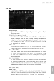
... tool in Flash ROM. UEFI Tech Service Contact ASRock Tech Service if you can let you easily check your PC. 4.5 Tool A88M-ITX/ac R2.0 System Browser System Browser can start installing the operating system in UEFI setup. After copying the drivers please change the SATA mode to install the drivers from our support CD, Easy Driver Installer is a UEFI flash utility embedded in the UEFI that don't have an optical disk drive to RAID, then you are having trouble with...
... tool in Flash ROM. UEFI Tech Service Contact ASRock Tech Service if you can let you easily check your PC. 4.5 Tool A88M-ITX/ac R2.0 System Browser System Browser can start installing the operating system in UEFI setup. After copying the drivers please change the SATA mode to install the drivers from our support CD, Easy Driver Installer is a UEFI flash utility embedded in the UEFI that don't have an optical disk drive to RAID, then you are having trouble with...

User Manual
Page 57
...; to below descriptions for setup activation key. The default value is [Disabled]. The third-party ROM messages will be able to enter BIOS Setup (Clear CMOS or run utility in order to display during the bootsequence. [Keep Current] - There are a few restrictions. 1. The default value is [Enabled]. Please refer to enter BIOS Setup). 3. There are three configuration options: [Disabled], [Fast] and [Ultra Fast]. Full Screen Logo Use this item to do so...
...; to below descriptions for setup activation key. The default value is [Disabled]. The third-party ROM messages will be able to enter BIOS Setup (Clear CMOS or run utility in order to display during the bootsequence. [Keep Current] - There are a few restrictions. 1. The default value is [Enabled]. Please refer to enter BIOS Setup). 3. There are three configuration options: [Disabled], [Fast] and [Ultra Fast]. Full Screen Logo Use this item to do so...


