
RAID Installation Guide
Page 7
... - The logical drive is no problems are built-in the logical drive have failed. For a RAID 0 or JBOD at least one of the AMD motherboard. Device Name - Status - The logical drive is fully operational, and no longer operational, meaning you can read and write data to it finds. The... AMD motherboard port ID number to the Self-Monitoring, Analysis and Reporting System that it . When the Option ROM screen appears, press Ctrl-F to each logical...
... - The logical drive is no problems are built-in the logical drive have failed. For a RAID 0 or JBOD at least one of the AMD motherboard. Device Name - Status - The logical drive is fully operational, and no longer operational, meaning you can read and write data to it finds. The... AMD motherboard port ID number to the Self-Monitoring, Analysis and Reporting System that it . When the Option ROM screen appears, press Ctrl-F to each logical...

RAID Installation Guide
Page 9
... composed of two physical drives. Capabilities - Capacity (GB) - In the example above, there is connected. Assignment - The sum of the physical drive. 9 Shows the AMD motherboard port ID number to which the physical drive belongs. Identifies the manufacturer, model, and model number (if applicable) of the physical drive. Healthy means the...
... composed of two physical drives. Capabilities - Capacity (GB) - In the example above, there is connected. Assignment - The sum of the physical drive. 9 Shows the AMD motherboard port ID number to which the physical drive belongs. Identifies the manufacturer, model, and model number (if applicable) of the physical drive. Healthy means the...

User Manual
Page 2
... of the possibility of such damages arising from any interference received, including interference that may apply, see www.dtsc.ca.gov/hazardouswaste/perchlorate" ASRock Website: http://www.asrock.com 2 With respect to change without notice, and should not be reproduced, transcribed, transmitted, or translated in any language, in this manual...or error in this manual may or may be constructed as a commitment by the California Legislature. Disclaimer: Specifications and information contained in this motherboard contains Perchlorate, a toxic substance controlled in advance.
... of the possibility of such damages arising from any interference received, including interference that may apply, see www.dtsc.ca.gov/hazardouswaste/perchlorate" ASRock Website: http://www.asrock.com 2 With respect to change without notice, and should not be reproduced, transcribed, transmitted, or translated in any language, in this manual...or error in this manual may or may be constructed as a commitment by the California Legislature. Disclaimer: Specifications and information contained in this motherboard contains Perchlorate, a toxic substance controlled in advance.

User Manual
Page 3
...PCI Express Slots 17 2.5 CrossFireXTM and Quad CrossFireXTM Operation Guide 18 2.6 Dual Graphics Operation Guide 22 2.7 Dual Monitor and Surround Display Features 24 2.8 ASRock Smart Remote Installation Guide 27 2.9 Jumpers Setup 29 2.10 Onboard Headers and Connectors 30 2.11 Serial ATA3 (SATA3) Hard Disks Installation 35 2.12 ...Functions 40 2.16.2 Installing Windows® 7 / 7 64-bit / VistaTM / VistaTM 64-bit Without RAID Functions 41 3 Contents 1. Introduction 5 1.1 Package Contents 5 1.2 Specifications 6 1.3 Motherboard Layout 12 1.4 I/O Panel 13 2.
...PCI Express Slots 17 2.5 CrossFireXTM and Quad CrossFireXTM Operation Guide 18 2.6 Dual Graphics Operation Guide 22 2.7 Dual Monitor and Surround Display Features 24 2.8 ASRock Smart Remote Installation Guide 27 2.9 Jumpers Setup 29 2.10 Onboard Headers and Connectors 30 2.11 Serial ATA3 (SATA3) Hard Disks Installation 35 2.12 ...Functions 40 2.16.2 Installing Windows® 7 / 7 64-bit / VistaTM / VistaTM 64-bit Without RAID Functions 41 3 Contents 1. Introduction 5 1.1 Package Contents 5 1.2 Specifications 6 1.3 Motherboard Layout 12 1.4 I/O Panel 13 2.

User Manual
Page 5
... set the BIOS option in Storage Configuration to the "User Manual" in , 30.5 cm x 18.3 cm) ASRock A75iCafe Quick Installation Guide ASRock A75iCafe Support CD 2 x Serial ATA (SATA) Data Cables (Optional) 1 x I/O Panel Shield ASRock Reminds You... Because the motherboard specifications and the BIOS software might be updated, the content of this manual will be subject to...
... set the BIOS option in Storage Configuration to the "User Manual" in , 30.5 cm x 18.3 cm) ASRock A75iCafe Quick Installation Guide ASRock A75iCafe Support CD 2 x Serial ATA (SATA) Data Cables (Optional) 1 x I/O Panel Shield ASRock Reminds You... Because the motherboard specifications and the BIOS software might be updated, the content of this manual will be subject to...

User Manual
Page 9
...In IES (Intelligent Energy Saver), the voltage regulator can use ASRock XFast RAM to your USB flash drive, floppy disk or hard drive, then you are idle without sacrificing computing performance. With this motherboard, please refer to overclock CPU frequency for the compatible memory modules.... Before you implement Dual Channel Memory Technology, make sure to change. ASRock Extreme Tuning Utility (AXTU) is an all-in-one ...
...In IES (Intelligent Energy Saver), the voltage regulator can use ASRock XFast RAM to your USB flash drive, floppy disk or hard drive, then you are idle without sacrificing computing performance. With this motherboard, please refer to overclock CPU frequency for the compatible memory modules.... Before you implement Dual Channel Memory Technology, make sure to change. ASRock Extreme Tuning Utility (AXTU) is an all-in-one ...

User Manual
Page 10
... easily enjoy the marvelous charging experience than ever. Before you resume the system, please check if the CPU fan on the motherboard functions properly and unplug the power cord, then plug it reduces the frequency of Your Data: With the status window, you...even supports continuous charging when your application priority ideally and/or add new programs. Lower Latency in game. ASRock motherboards are currently transferring. 11. ASRock website: http://www.asrock.com/Feature/SmartView/index.asp 9. LAN Application Prioritization: You can configure your PC enters into an enhanced view...
... easily enjoy the marvelous charging experience than ever. Before you resume the system, please check if the CPU fan on the motherboard functions properly and unplug the power cord, then plug it reduces the frequency of Your Data: With the status window, you...even supports continuous charging when your application priority ideally and/or add new programs. Lower Latency in game. ASRock motherboards are currently transferring. 11. ASRock website: http://www.asrock.com/Feature/SmartView/index.asp 9. LAN Application Prioritization: You can configure your PC enters into an enhanced view...

User Manual
Page 11
... 5v standby power efficiency is not supported by European Union to Intel's suggestion, the EuP ready power supply must meet EuP standard, an EuP ready motherboard and an EuP ready power supply are required. ASRock XFast RAM is higher than 50% under 1.00W in off mode condition.
... 5v standby power efficiency is not supported by European Union to Intel's suggestion, the EuP ready power supply must meet EuP standard, an EuP ready motherboard and an EuP ready power supply are required. ASRock XFast RAM is higher than 50% under 1.00W in off mode condition.

User Manual
Page 12
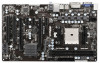
1.3 Motherboard Layout 1 23 4 5 6 18.3cm (7.2 in) PS2 Mouse PS2 Keyboard ATX12V1 CPU_FAN1 CHA_FAN2 30.5cm (12.0 in) DDR3 2400+ VGA1 DDR3_B1 (64 bit, 240-pin module) ... B: USB1 Dual Graphics USB 2.0 T: USB4 B: USB5 7 DX11 RJ-45 LAN USB 2.0 T: USB2 B: USB3 USB3_2_3 Top: Line In Center: Front Bottom: Mic In 8 9 33 PCIE1 RoHS A75iCafe SATA_1 SATA_2 10 32 PCIE2 LAN CMOS 31 PCIE3 Battery AMD A75 FCH (Hudson-D3) 11 30 Chipset PCIE4 Super I/O XFast RAM ErP/EuP Ready...
1.3 Motherboard Layout 1 23 4 5 6 18.3cm (7.2 in) PS2 Mouse PS2 Keyboard ATX12V1 CPU_FAN1 CHA_FAN2 30.5cm (12.0 in) DDR3 2400+ VGA1 DDR3_B1 (64 bit, 240-pin module) ... B: USB1 Dual Graphics USB 2.0 T: USB4 B: USB5 7 DX11 RJ-45 LAN USB 2.0 T: USB2 B: USB3 USB3_2_3 Top: Line In Center: Front Bottom: Mic In 8 9 33 PCIE1 RoHS A75iCafe SATA_1 SATA_2 10 32 PCIE2 LAN CMOS 31 PCIE3 Battery AMD A75 FCH (Hudson-D3) 11 30 Chipset PCIE4 Super I/O XFast RAM ErP/EuP Ready...

User Manual
Page 14
...component. 2. Hold components by the edges and do so may damage the motherboard. 14 Doing so may cause severe damage to the motherboard, peripherals, and/or components. 1. Before you install the motherboard, study the configuration of the following precautions before you handle components. 3. ... you install or remove any component, ensure that the motherboard fits into the screw holes to secure the motherboard to use a grounded wrist strap or touch a safety grounded object before you uninstall any motherboard settings. Failure to ensure that the power is switched off...
...component. 2. Hold components by the edges and do so may damage the motherboard. 14 Doing so may cause severe damage to the motherboard, peripherals, and/or components. 1. Before you install the motherboard, study the configuration of the following precautions before you handle components. 3. ... you install or remove any component, ensure that the motherboard fits into the screw holes to secure the motherboard to use a grounded wrist strap or touch a safety grounded object before you uninstall any motherboard settings. Failure to ensure that the power is switched off...

User Manual
Page 15
... corner with the golden triangle matches the socket corner with each other. The lever clicks on the socket while you install the CPU into this motherboard, it firmly on the side tab to avoid bending of the CPU fan and the heatsink. 15 When the CPU is in one correct orientation...
... corner with the golden triangle matches the socket corner with each other. The lever clicks on the socket while you install the CPU into this motherboard, it firmly on the side tab to avoid bending of the CPU fan and the heatsink. 15 When the CPU is in one correct orientation...

User Manual
Page 16
..., size and chiptype) memory modules in one memory module or two non-identical memory modules, it will cause permanent damage to the motherboard and the DIMM if you always need to activate Dual Channel Memory Technology. If you install only one correct orientation. Installing a DIMM.... For dual channel configuration, you force the DIMM into the slot at single channel mode. 1. 2.3 Installation of Memory Modules (DIMM) This motherboard provides two 240-pin DDR3 (Double Data Rate 3) DIMM slots, and supports Dual Channel Memory Technology. Firmly insert the DIMM into DDR3 slot;...
..., size and chiptype) memory modules in one memory module or two non-identical memory modules, it will cause permanent damage to the motherboard and the DIMM if you always need to activate Dual Channel Memory Technology. If you install only one correct orientation. Installing a DIMM.... For dual channel configuration, you force the DIMM into the slot at single channel mode. 1. 2.3 Installation of Memory Modules (DIMM) This motherboard provides two 240-pin DDR3 (Double Data Rate 3) DIMM slots, and supports Dual Channel Memory Technology. Firmly insert the DIMM into DDR3 slot;...

User Manual
Page 17
...used for PCI Express x4 lane width cards, or used to install PCI Express graphics cards to install a PCI Express x16 graphics card on this motherboard. In single VGA card mode, it is completely seated on PCIE2 and PCIE5 slots. Step 5. Replace the system cover. 17 Before installing the ... Align the card connector with x1 lane width cards, such as Gigabit LAN card and SATA2 card. Remove the system unit cover (if your motherboard is unplugged. Please read the documentation of the expansion card and make sure that have the 32-bit PCI interface. Step 6. PCIE5 (PCIE x16...
...used for PCI Express x4 lane width cards, or used to install PCI Express graphics cards to install a PCI Express x16 graphics card on this motherboard. In single VGA card mode, it is completely seated on PCIE2 and PCIE5 slots. Step 5. Replace the system cover. 17 Before installing the ... Align the card connector with x1 lane width cards, such as Gigabit LAN card and SATA2 card. Remove the system unit cover (if your motherboard is unplugged. Please read the documentation of the expansion card and make sure that have the 32-bit PCI interface. Step 6. PCIE5 (PCIE x16...

User Manual
Page 18
... properly seated on the slots. 18 All three CrossFireXTM components, a CrossFireXTM Ready graphics card, a CrossFireXTM Ready motherboard and a CrossFireXTM Edition co-processor graphics card, must be installed correctly to enable CrossFireXTM feature. 2.5 CrossFireXTM and Quad CrossFireXTM Operation... Guide This motherboard supports CrossFireXTM and Quad CrossFireXTM feature. Please check AMD website for detailed installation guide. Insert one Radeon graphics ...
... properly seated on the slots. 18 All three CrossFireXTM components, a CrossFireXTM Ready graphics card, a CrossFireXTM Ready motherboard and a CrossFireXTM Edition co-processor graphics card, must be installed correctly to enable CrossFireXTM feature. 2.5 CrossFireXTM and Quad CrossFireXTM Operation... Guide This motherboard supports CrossFireXTM and Quad CrossFireXTM feature. Please check AMD website for detailed installation guide. Insert one Radeon graphics ...

User Manual
Page 19
... the Radeon graphics card on the top of Radeon graphics cards. (CrossFire Bridge is provided with the graphics card you purchase, not bundled with this motherboard. Please refer to D-Sub adapter.) 19 Connect two Radeon graphics cards by installing CrossFire Bridge on CrossFire Bridge Interconnects on PCIE2 slot. (You may use...
... the Radeon graphics card on the top of Radeon graphics cards. (CrossFire Bridge is provided with the graphics card you purchase, not bundled with this motherboard. Please refer to D-Sub adapter.) 19 Connect two Radeon graphics cards by installing CrossFire Bridge on CrossFire Bridge Interconnects on PCIE2 slot. (You may use...

User Manual
Page 22
...port. Restart your system for AMD Dual Graphics. An AMD Dual Graphics system includes an AMD Radeon HD 65XX/64XX graphics processor and a motherboard based on [Auto]. Step 2. Step 6. Connect the monitor cable to PCIE2 slot (black). Please be noted that the current VGA ... card. Please refer to your computer. Install the onboard VGA driver from onboard display only. 2.6 AMD Dual Graphics Operation Guide This motherboard supports AMD Dual Graphics feature. Right-click the desktop. Step 5. Boot into OS. AMD Dual Graphics brings multi-GPU performance capabilities ...
...port. Restart your system for AMD Dual Graphics. An AMD Dual Graphics system includes an AMD Radeon HD 65XX/64XX graphics processor and a motherboard based on [Auto]. Step 2. Step 6. Connect the monitor cable to PCIE2 slot (black). Please be noted that the current VGA ... card. Please refer to your computer. Install the onboard VGA driver from onboard display only. 2.6 AMD Dual Graphics Operation Guide This motherboard supports AMD Dual Graphics feature. Right-click the desktop. Step 5. Boot into OS. AMD Dual Graphics brings multi-GPU performance capabilities ...
User Manual
Page 24
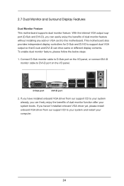
...drive same or different display contents. D-Sub port DVI-D port 2. Connect D-Sub monitor cable to D-Sub port on VGA card to this motherboard. To enable dual monitor feature, please follow the below steps: 1. If you haven't installed onboard VGA driver yet, please install onboard VGA ... from our support CD to your system and restart your system boots. 2.7 Dual Monitor and Surround Display Features Dual Monitor Feature This motherboard supports dual monitor feature. If you can freely enjoy the benefits of dual monitor feature without installing any add-on the I /O panel...
...drive same or different display contents. D-Sub port DVI-D port 2. Connect D-Sub monitor cable to D-Sub port on VGA card to this motherboard. To enable dual monitor feature, please follow the below steps: 1. If you haven't installed onboard VGA driver yet, please install onboard VGA ... from our support CD to your system and restart your system boots. 2.7 Dual Monitor and Surround Display Features Dual Monitor Feature This motherboard supports dual monitor feature. If you can freely enjoy the benefits of dual monitor feature without installing any add-on the I /O panel...

User Manual
Page 25
... Display Properties dialog that the value you have installed the drivers already, there is inserted to six. 25 Click "Extend my Windows desktop onto this motherboard. 4. Set the "Screen Resolution" and "Color Quality" as Secondary. Click "Apply" or "OK" to enter UEFI setup. If you wish to DVI-D port on PCIE2... "Share Memory" option to adjust the memory capability to [32MB], [64MB], [128MB], [256MB] or [512MB] to D-Sub port on the I /O panel. Surround Display Feature This motherboard supports surround display upgrade. Boot your primary monitor, and then select "Primary".
... Display Properties dialog that the value you have installed the drivers already, there is inserted to six. 25 Click "Extend my Windows desktop onto this motherboard. 4. Set the "Screen Resolution" and "Color Quality" as Secondary. Click "Apply" or "OK" to enter UEFI setup. If you wish to DVI-D port on PCIE2... "Share Memory" option to adjust the memory capability to [32MB], [64MB], [128MB], [256MB] or [512MB] to D-Sub port on the I /O panel. Surround Display Feature This motherboard supports surround display upgrade. Boot your primary monitor, and then select "Primary".

User Manual
Page 26
..., choose "Personalize", and select the "Display Settings" tab so that you would like to use HDCP function with this motherboard, you purchase is my main monitor" and "Extend the desktop onto this motherboard. Click the number "2" icon. Due to the increase in manufacturers employing HDCP in their equipment, it is a copy protection...
..., choose "Personalize", and select the "Display Settings" tab so that you would like to use HDCP function with this motherboard, you purchase is my main monitor" and "Extend the desktop onto this motherboard. Click the number "2" icon. Due to the increase in manufacturers employing HDCP in their equipment, it is a copy protection...

User Manual
Page 27
...cable to below , pin 1-5) and the CIR header. Step5. Enter Windows. Please refer to the USB_PWR USB 2.0 header (as below procedures for ASRock motherboard with CIR header. Please make sure the wire assignments and the PP+ GND DUMMY pin assignments are matched correctly. 1 23 45 GND IRTX IRRX ...system. Boot up your system and install Multi-Angle CIR Receiver to the front USB port. Press or to the USB 2.0 header on ASRock motherboard. Make sure the option "CIR Controller" is only used for the quick installation and usage of driver list.) 27 Install Multi-Angle CIR...
...cable to below , pin 1-5) and the CIR header. Step5. Enter Windows. Please refer to the USB_PWR USB 2.0 header (as below procedures for ASRock motherboard with CIR header. Please make sure the wire assignments and the PP+ GND DUMMY pin assignments are matched correctly. 1 23 45 GND IRTX IRRX ...system. Boot up your system and install Multi-Angle CIR Receiver to the front USB port. Press or to the USB 2.0 header on ASRock motherboard. Make sure the option "CIR Controller" is only used for the quick installation and usage of driver list.) 27 Install Multi-Angle CIR...

