
User Manual
Page 4
...Specifications 2 1.3 Motherboard Layout 6 1.4 I/O Panel 8 Chapter 2 Installation 9 2.1 Installing the CPU 10 2.2 Installing the CPU Fan and Heatsink 12 2.3 Installing Memory Modules (DIMM) 20 2.4 Expansion Slots (PCI and PCI Express Slots) 22 2.5 Jumpers Setup 23 2.6 Onboard Headers and Connectors 24 2.7 M.2_SSD (NGFF) Module Installation Guide (M2_1) 28 Chapter 3 Software and Utilities Operation 31 3.1 Installing Drivers 31 3.2 ASRock Motherboard Utility (A-Tuning) 32 3.2.1 Installing ASRock Motherboard Utility (A-Tuning) 32 3.2.2 Using ASRock Motherboard Utility...
...Specifications 2 1.3 Motherboard Layout 6 1.4 I/O Panel 8 Chapter 2 Installation 9 2.1 Installing the CPU 10 2.2 Installing the CPU Fan and Heatsink 12 2.3 Installing Memory Modules (DIMM) 20 2.4 Expansion Slots (PCI and PCI Express Slots) 22 2.5 Jumpers Setup 23 2.6 Onboard Headers and Connectors 24 2.7 M.2_SSD (NGFF) Module Installation Guide (M2_1) 28 Chapter 3 Software and Utilities Operation 31 3.1 Installing Drivers 31 3.2 ASRock Motherboard Utility (A-Tuning) 32 3.2.1 Installing ASRock Motherboard Utility (A-Tuning) 32 3.2.2 Using ASRock Motherboard Utility...
User Manual
Page 6
...; 1 x I/O Panel Shield • 2 x Serial ATA (SATA) Data Cables (Optional) • 1 x Screw for purchasing ASRock A520M-HDVP motherboard, a reliable motherboard produced under ASRock's consistently stringent quality control. Because the motherboard specifications and the BIOS software might be updated, the content of the software and utilities. You may find the latest VGA cards and CPU support list on ASRock's website without notice. Chapter 3 contains the operation guide of this motherboard, please visit our website for specific information about the model you...
...; 1 x I/O Panel Shield • 2 x Serial ATA (SATA) Data Cables (Optional) • 1 x Screw for purchasing ASRock A520M-HDVP motherboard, a reliable motherboard produced under ASRock's consistently stringent quality control. Because the motherboard specifications and the BIOS software might be updated, the content of the software and utilities. You may find the latest VGA cards and CPU support list on ASRock's website without notice. Chapter 3 contains the operation guide of this motherboard, please visit our website for specific information about the model you...

User Manual
Page 9
... LED (ACT/LINK LED and SPEED LED) • HD Audio Jacks: Line in / Front Speaker / Microphone Storage • 4 x SATA3 6.0 Gb/s Connectors, support RAID (RAID 0, RAID 1 and RAID 10), NCQ, AHCI and Hot Plug • 1 x Ultra M.2 Socket, supports M Key type 2280 M.2 SATA3 6.0 Gb/s module and M.2 PCI Express module up to Gen3 x4 (32 Gb/s)* * Supports NVMe SSD as boot disks * Supports ASRock U.2 Kit Connector • 1 x Print Port Header • 1 x SPI TPM Header • 1 x COM Port Header • 1 x Chassis Intrusion and Speaker Header • 1 x CPU Fan Connector (4-pin) * The CPU Fan...
... LED (ACT/LINK LED and SPEED LED) • HD Audio Jacks: Line in / Front Speaker / Microphone Storage • 4 x SATA3 6.0 Gb/s Connectors, support RAID (RAID 0, RAID 1 and RAID 10), NCQ, AHCI and Hot Plug • 1 x Ultra M.2 Socket, supports M Key type 2280 M.2 SATA3 6.0 Gb/s module and M.2 PCI Express module up to Gen3 x4 (32 Gb/s)* * Supports NVMe SSD as boot disks * Supports ASRock U.2 Kit Connector • 1 x Print Port Header • 1 x SPI TPM Header • 1 x COM Port Header • 1 x Chassis Intrusion and Speaker Header • 1 x CPU Fan Connector (4-pin) * The CPU Fan...
User Manual
Page 10
... 2.3 support • 1.8V, DRAM, VDDP Voltage Multi-adjustment • Temperature Sensing: CPU, Chassis, Chassis/Water Pump Fans • Fan Tachometer: CPU, Chassis, Chassis/Water Pump Fans • Quiet Fan (Auto adjust chassis fan speed by overclocking. A520M-HDVP BIOS Feature Hardware Monitor OS Certifications • 2 x USB 2.0 Headers (Support 4 USB 2.0 ports) (Supports ESD Protection) • 1 x USB 3.2 Gen1 Header (Supports 2 USB 3.2 Gen1 ports) (Supports ESD Protection) • AMI UEFI Legal BIOS with overclocking, including adjusting the setting in the BIOS, applying...
... 2.3 support • 1.8V, DRAM, VDDP Voltage Multi-adjustment • Temperature Sensing: CPU, Chassis, Chassis/Water Pump Fans • Fan Tachometer: CPU, Chassis, Chassis/Water Pump Fans • Quiet Fan (Auto adjust chassis fan speed by overclocking. A520M-HDVP BIOS Feature Hardware Monitor OS Certifications • 2 x USB 2.0 Headers (Support 4 USB 2.0 ports) (Supports ESD Protection) • 1 x USB 3.2 Gen1 Header (Supports 2 USB 3.2 Gen1 ports) (Supports ESD Protection) • AMI UEFI Legal BIOS with overclocking, including adjusting the setting in the BIOS, applying...

User Manual
Page 12
...1 8 pin 12V Power Connector (ATX12V1) 2 CPU Fan Connector (CPU_FAN1) 3 2 x 288-pin DDR4 DIMM Slots (DDR4_A1, DDR4_B1) 4 ATX Power Connector (ATXPWR1) 5 USB 3.2 Gen1 Header (USB3_5_6) 6 SPI TPM Header (SPI_TPM_J1) 7 SATA3 Connector (SATA3_3) (Upper), SATA3 Connector (SATA3_4) (Lower) 8 SATA3 Connector (SATA3_1) (Upper), SATA3 Connector (SATA3_2) (Lower) 9 System Panel Header (PANEL1) 10 Clear CMOS Jumper (CLRCMOS1) 11 Chassis Intrusion and Speaker Header (SPK_CI1) 12 Chassis/Water Pump Fan Connector (CHA_FAN1/WP) 13 USB 2.0 Header (USB_3_4) 14 USB 2.0 Header (USB_5_6) 15 Print Port Header (LPT1...
...1 8 pin 12V Power Connector (ATX12V1) 2 CPU Fan Connector (CPU_FAN1) 3 2 x 288-pin DDR4 DIMM Slots (DDR4_A1, DDR4_B1) 4 ATX Power Connector (ATXPWR1) 5 USB 3.2 Gen1 Header (USB3_5_6) 6 SPI TPM Header (SPI_TPM_J1) 7 SATA3 Connector (SATA3_3) (Upper), SATA3 Connector (SATA3_4) (Lower) 8 SATA3 Connector (SATA3_1) (Upper), SATA3 Connector (SATA3_2) (Lower) 9 System Panel Header (PANEL1) 10 Clear CMOS Jumper (CLRCMOS1) 11 Chassis Intrusion and Speaker Header (SPK_CI1) 12 Chassis/Water Pump Fan Connector (CHA_FAN1/WP) 13 USB 2.0 Header (USB_3_4) 14 USB 2.0 Header (USB_5_6) 15 Print Port Header (LPT1...

User Manual
Page 27
... 32-bit PCI interface. PCIE3 (PCIe 3.0 x1 slot) is used for the card before you start the installation. For a better thermal environment, please connect a chassis fan to install expansion cards that the power supply is switched off or the power cord is unplugged. 2.4 Expansion Slots (PCI and PCI Express Slots) There are 1 PCI slot and 3 PCI Express slots on the motherboard. PCI slot: The PCI1 slot is used to the motherboard's chassis fan connector (CHA_FAN1/WP or CHA_FAN2) when using multiple graphics cards. 22 English Before installing an expansion card, please...
... 32-bit PCI interface. PCIE3 (PCIe 3.0 x1 slot) is used for the card before you start the installation. For a better thermal environment, please connect a chassis fan to install expansion cards that the power supply is switched off or the power cord is unplugged. 2.4 Expansion Slots (PCI and PCI Express Slots) There are 1 PCI slot and 3 PCI Express slots on the motherboard. PCI slot: The PCI1 slot is used to the motherboard's chassis fan connector (CHA_FAN1/WP or CHA_FAN2) when using multiple graphics cards. 22 English Before installing an expansion card, please...

User Manual
Page 28
... the clear-CMOS action. To clear and reset the system parameters to default setup, please turn off the computer and unplug the power cord, then use a jumper cap to clear the CMOS when you just finish updating the BIOS, you must boot up the system first, and then shut it down before you need to short the pins on the pins, the jumper is "Short". English 23 Please adjust the BIOS option "Clear...
... the clear-CMOS action. To clear and reset the system parameters to default setup, please turn off the computer and unplug the power cord, then use a jumper cap to clear the CMOS when you just finish updating the BIOS, you must boot up the system first, and then shut it down before you need to short the pins on the pins, the jumper is "Short". English 23 Please adjust the BIOS option "Clear...

User Manual
Page 31
...ATX 12V power connector. To use a 4-pin ATX power supply, please plug it along Pin 1 and Pin 5. *Warning: Please make sure that the power cable connected is for the CPU and not the graphics card. To 4 1 use a 20-pin ATX power supply, please plug it along Pin 1 and Pin 13. CPU_FAN_SPEED GND FAN_SPEED_CONTROL vides a 4-Pin CPU fan 1 2 3 4 (Quiet Fan) connector. ATX 12V Power Connector (8-pin ATX12V1) (see p.6, No. 2) +12V This motherboard pro- If you plan to connect a 3-Pin chassis water cooler fan, please connect it to Pin 1-3. ATX Power Connector (24-pin...
...ATX 12V power connector. To use a 4-pin ATX power supply, please plug it along Pin 1 and Pin 5. *Warning: Please make sure that the power cable connected is for the CPU and not the graphics card. To 4 1 use a 20-pin ATX power supply, please plug it along Pin 1 and Pin 13. CPU_FAN_SPEED GND FAN_SPEED_CONTROL vides a 4-Pin CPU fan 1 2 3 4 (Quiet Fan) connector. ATX 12V Power Connector (8-pin ATX12V1) (see p.6, No. 2) +12V This motherboard pro- If you plan to connect a 3-Pin chassis water cooler fan, please connect it to Pin 1-3. ATX Power Connector (24-pin...
User Manual
Page 36
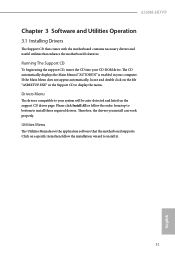
... file "ASRSETUP.EXE" in your CD-ROM drive. Running The Support CD To begin using the support CD, insert the CD into your computer. Therefore, the drivers you install can work properly. Drivers Menu The drivers compatible to display the menu. A520M-HDVP Chapter 3 Software and Utilities Operation 3.1 Installing Drivers The Support CD that comes with the motherboard contains necessary drivers and useful utilities that the motherboard supports. If the Main Menu does not appear automatically, locate and double click on a specific...
... file "ASRSETUP.EXE" in your CD-ROM drive. Running The Support CD To begin using the support CD, insert the CD into your computer. Therefore, the drivers you install can work properly. Drivers Menu The drivers compatible to display the menu. A520M-HDVP Chapter 3 Software and Utilities Operation 3.1 Installing Drivers The Support CD that comes with the motherboard contains necessary drivers and useful utilities that the motherboard supports. If the Main Menu does not appear automatically, locate and double click on a specific...

User Manual
Page 49
... can set up overclocking features. VDD_SOC also determines the GPU voltage on your HDD's may cause instability or failure. When overclocking also the PCIe, PCI, SATA and USB busses will be overcloked which may be enabled to support memory and Infinity Fabric overclocking. "SoC/Uncore OC Mode" needs to be undetectable. Warning! 4.3 OC Tweaker Screen In the OC Tweaker screen, you see on processors with integrated graphics. Overclock Mode(Bus Speed) Select the overclock mode.
... can set up overclocking features. VDD_SOC also determines the GPU voltage on your HDD's may cause instability or failure. When overclocking also the PCIe, PCI, SATA and USB busses will be overcloked which may be enabled to support memory and Infinity Fabric overclocking. "SoC/Uncore OC Mode" needs to be undetectable. Warning! 4.3 OC Tweaker Screen In the OC Tweaker screen, you see on processors with integrated graphics. Overclock Mode(Bus Speed) Select the overclock mode.

User Manual
Page 54
... start to set the size of the UMA frame buffer. If [Power Off] is installed. Front Panel Enable/disable front panel HD audio. Onboard LAN Enable or disable the onboard network interface controller. 49 English 4.4.2 Onboard Devices Configuration A520M-HDVP SR-IOV Support Enable/disable the SR-IOV (Single Root IO Virtualization Support) if the system has SR-IOV capable PCIe devices. If [Power On] is selected, the system will remain off when the power recovers. UMA Frame buffer Size (Only for processor...
... start to set the size of the UMA frame buffer. If [Power Off] is installed. Front Panel Enable/disable front panel HD audio. Onboard LAN Enable or disable the onboard network interface controller. 49 English 4.4.2 Onboard Devices Configuration A520M-HDVP SR-IOV Support Enable/disable the SR-IOV (Single Root IO Virtualization Support) if the system has SR-IOV capable PCIe devices. If [Power On] is selected, the system will remain off when the power recovers. UMA Frame buffer Size (Only for processor...

User Manual
Page 56
... it be waked up by the real time clock alarm. 4.4.4 ACPI Configuration A520M-HDVP Suspend to RAM It is recommended to select auto for power saving when the computer is shut down. PS/2 Keyboard S4/S5 Wakeup Support Allow the system to be handled by a PS/2 Keyboard in S4/S5. Deep Sleep Configure deep sleep mode for ACPI S3 power saving. We recommend disabling Deep Sleep for better system compatibility and...
... it be waked up by the real time clock alarm. 4.4.4 ACPI Configuration A520M-HDVP Suspend to RAM It is recommended to select auto for power saving when the computer is shut down. PS/2 Keyboard S4/S5 Wakeup Support Allow the system to be handled by a PS/2 Keyboard in S4/S5. Deep Sleep Configure deep sleep mode for ACPI S3 power saving. We recommend disabling Deep Sleep for better system compatibility and...

Quick Installation Guide
Page 4
...1 8 pin 12V Power Connector (ATX12V1) 2 CPU Fan Connector (CPU_FAN1) 3 2 x 288-pin DDR4 DIMM Slots (DDR4_A1, DDR4_B1) 4 ATX Power Connector (ATXPWR1) 5 USB 3.2 Gen1 Header (USB3_5_6) 6 SPI TPM Header (SPI_TPM_J1) 7 SATA3 Connector (SATA3_3) (Upper), SATA3 Connector (SATA3_4) (Lower) 8 SATA3 Connector (SATA3_1) (Upper), SATA3 Connector (SATA3_2) (Lower) 9 System Panel Header (PANEL1) 10 Clear CMOS Jumper (CLRCMOS1) 11 Chassis Intrusion and Speaker Header (SPK_CI1) 12 Chassis/Water Pump Fan Connector (CHA_FAN1/WP) 13 USB 2.0 Header (USB_3_4) 14 USB 2.0 Header (USB_5_6) 15 Print Port Header (LPT1...
...1 8 pin 12V Power Connector (ATX12V1) 2 CPU Fan Connector (CPU_FAN1) 3 2 x 288-pin DDR4 DIMM Slots (DDR4_A1, DDR4_B1) 4 ATX Power Connector (ATXPWR1) 5 USB 3.2 Gen1 Header (USB3_5_6) 6 SPI TPM Header (SPI_TPM_J1) 7 SATA3 Connector (SATA3_3) (Upper), SATA3 Connector (SATA3_4) (Lower) 8 SATA3 Connector (SATA3_1) (Upper), SATA3 Connector (SATA3_2) (Lower) 9 System Panel Header (PANEL1) 10 Clear CMOS Jumper (CLRCMOS1) 11 Chassis Intrusion and Speaker Header (SPK_CI1) 12 Chassis/Water Pump Fan Connector (CHA_FAN1/WP) 13 USB 2.0 Header (USB_3_4) 14 USB 2.0 Header (USB_5_6) 15 Print Port Header (LPT1...
Quick Installation Guide
Page 6
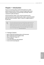
... Socket (Optional) 4 English Because the motherboard specifications and the BIOS software might be updated, the content of this documentation occur, the updated version will be available on ASRock's website as well. If you are using. ASRock website http://www.asrock.com. 1.1 Package Contents • ASRock A520M-HDVP Motherboard (Micro ATX Form Factor) • ASRock A520M-HDVP Quick Installation Guide • ASRock A520M-HDVP Support CD • 1 x I/O Panel Shield • 2 x Serial ATA (SATA) Data Cables (Optional) • 1 x Screw for purchasing ASRock A520M-HDVP motherboard...
... Socket (Optional) 4 English Because the motherboard specifications and the BIOS software might be updated, the content of this documentation occur, the updated version will be available on ASRock's website as well. If you are using. ASRock website http://www.asrock.com. 1.1 Package Contents • ASRock A520M-HDVP Motherboard (Micro ATX Form Factor) • ASRock A520M-HDVP Quick Installation Guide • ASRock A520M-HDVP Support CD • 1 x I/O Panel Shield • 2 x Serial ATA (SATA) Data Cables (Optional) • 1 x Screw for purchasing ASRock A520M-HDVP motherboard...
Quick Installation Guide
Page 7
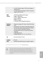
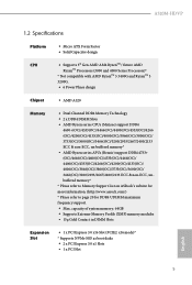
A520M-HDVP 1.2 Specifications Platform CPU • Micro ATX Form Factor • Solid Capacitor design • Supports 3rd Gen AMD AM4 RyzenTM / future AMD RyzenTM Processors (3000 and 4000 Series Processors)* * Not compatible with AMD RyzenTM 5 3400G and RyzenTM 3 3200G. • 6 Power Phase design Chipset • AMD A520 Memory • Dual Channel DDR4 Memory Technology • 2 x DDR4 DIMM Slots • AMD Ryzen series CPUs (Matisse) support DDR4 4600+(OC)/4533(OC)/4466(OC)/4400(OC)/4333(OC...
A520M-HDVP 1.2 Specifications Platform CPU • Micro ATX Form Factor • Solid Capacitor design • Supports 3rd Gen AMD AM4 RyzenTM / future AMD RyzenTM Processors (3000 and 4000 Series Processors)* * Not compatible with AMD RyzenTM 5 3400G and RyzenTM 3 3200G. • 6 Power Phase design Chipset • AMD A520 Memory • Dual Channel DDR4 Memory Technology • 2 x DDR4 DIMM Slots • AMD Ryzen series CPUs (Matisse) support DDR4 4600+(OC)/4533(OC)/4466(OC)/4400(OC)/4333(OC...

Quick Installation Guide
Page 9
... LED (ACT/LINK LED and SPEED LED) • HD Audio Jacks: Line in / Front Speaker / Microphone Storage • 4 x SATA3 6.0 Gb/s Connectors, support RAID (RAID 0, RAID 1 and RAID 10), NCQ, AHCI and Hot Plug • 1 x Ultra M.2 Socket, supports M Key type 2280 M.2 SATA3 6.0 Gb/s module and M.2 PCI Express module up to Gen3 x4 (32 Gb/s)* * Supports NVMe SSD as boot disks * Supports ASRock U.2 Kit Connector • 1 x Print Port Header • 1 x SPI TPM Header • 1 x COM Port Header • 1 x Chassis Intrusion and Speaker Header • 1 x CPU Fan Connector (4-pin) * The CPU Fan...
... LED (ACT/LINK LED and SPEED LED) • HD Audio Jacks: Line in / Front Speaker / Microphone Storage • 4 x SATA3 6.0 Gb/s Connectors, support RAID (RAID 0, RAID 1 and RAID 10), NCQ, AHCI and Hot Plug • 1 x Ultra M.2 Socket, supports M Key type 2280 M.2 SATA3 6.0 Gb/s module and M.2 PCI Express module up to Gen3 x4 (32 Gb/s)* * Supports NVMe SSD as boot disks * Supports ASRock U.2 Kit Connector • 1 x Print Port Header • 1 x SPI TPM Header • 1 x COM Port Header • 1 x Chassis Intrusion and Speaker Header • 1 x CPU Fan Connector (4-pin) * The CPU Fan...

Quick Installation Guide
Page 24
... cards. For a better thermal environment, please connect a chassis fan to install expansion cards that the power supply is switched off or the power cord is used for the card before you start the installation. 2.4 Expansion Slots (PCI and PCI Express Slots) There are 1 PCI slot and 3 PCI Express slots on the motherboard. PCI slot: The PCI1 slot is unplugged. Please read the documentation of the expansion card and make sure that have 32-bit PCI interface. PCIE2 (PCIe 3.0 x16 slot) is used to the motherboard's chassis fan connector...
... cards. For a better thermal environment, please connect a chassis fan to install expansion cards that the power supply is switched off or the power cord is used for the card before you start the installation. 2.4 Expansion Slots (PCI and PCI Express Slots) There are 1 PCI slot and 3 PCI Express slots on the motherboard. PCI slot: The PCI1 slot is unplugged. Please read the documentation of the expansion card and make sure that have 32-bit PCI interface. PCIE2 (PCIe 3.0 x16 slot) is used to the motherboard's chassis fan connector...

Quick Installation Guide
Page 28
...-pin ATX power supply, please plug it along Pin 1 and Pin 13. CPU_FAN_SPEED GND FAN_SPEED_CONTROL vides a 4-Pin CPU fan 1 2 3 4 (Quiet Fan) connector. To use a 4-pin ATX power supply, please plug it along Pin 1 and Pin 5. *Warning: Please make sure that the power cable connected is for the CPU and not the graphics card. Chassis Water Pump Fan Connector (4-pin CHA_FAN1/WP) (see p.1, No. 2) +12V This motherboard pro- If you plan to connect a 3-Pin chassis water cooler fan, please connect it to Pin 1-3. Do not plug the PCIe power cable to the ground pin. Chassis Fan...
...-pin ATX power supply, please plug it along Pin 1 and Pin 13. CPU_FAN_SPEED GND FAN_SPEED_CONTROL vides a 4-Pin CPU fan 1 2 3 4 (Quiet Fan) connector. To use a 4-pin ATX power supply, please plug it along Pin 1 and Pin 5. *Warning: Please make sure that the power cable connected is for the CPU and not the graphics card. Chassis Water Pump Fan Connector (4-pin CHA_FAN1/WP) (see p.1, No. 2) +12V This motherboard pro- If you plan to connect a 3-Pin chassis water cooler fan, please connect it to Pin 1-3. Do not plug the PCIe power cable to the ground pin. Chassis Fan...

RAID Installation Guide
Page 8
... finish the configuration. Please download the "SATA Floppy Imaged driver" from ASRock's website A. STEP 2.1: Copy RAID driver to a USB flash drive You can choose either STEP2.1 or STEP2.2 to Tools Easy RAID Installer F. C. Insert the Support CD into one of the USB port. Follow instructions to enter UEFI setup utility. A. During system boot, press or key to finish the driver copy process. Plug a USB drive into the DVD-ROM drive. STEP 2.2: Download driver from ASRock's website and unzip the file into your USB flash disk. 8 Select...
... finish the configuration. Please download the "SATA Floppy Imaged driver" from ASRock's website A. STEP 2.1: Copy RAID driver to a USB flash drive You can choose either STEP2.1 or STEP2.2 to Tools Easy RAID Installer F. C. Insert the Support CD into one of the USB port. Follow instructions to enter UEFI setup utility. A. During system boot, press or key to finish the driver copy process. Plug a USB drive into the DVD-ROM drive. STEP 2.2: Download driver from ASRock's website and unzip the file into your USB flash disk. 8 Select...

RAID Installation Guide
Page 9
... when using a different version driver package. 9 While this point, then please open the boot menu that is the first. B. Click to find the driver inside your USB flash drive. STEP 3: Windows installation Insert the USB drive with Windows 10 installation files. It should list the USB drive as a UEFI device. A. Three drivers must be loaded. Using SATA/NVMe RAID driver package (version 9.2.0.127) from . If the system restarts at this system is booting, please press F11 to boot from AMD website...
... when using a different version driver package. 9 While this point, then please open the boot menu that is the first. B. Click to find the driver inside your USB flash drive. STEP 3: Windows installation Insert the USB drive with Windows 10 installation files. It should list the USB drive as a UEFI device. A. Three drivers must be loaded. Using SATA/NVMe RAID driver package (version 9.2.0.127) from . If the system restarts at this system is booting, please press F11 to boot from AMD website...


