
User Manual
Page 7
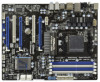
... Play" 7 Front panel audio connector - 3 x USB 2.0 headers (support 6 USB 2.0 ports) - 1 x USB 3.0 header (supports 2 USB 3.0 ports) - 1 x Dr. Debug (7-Segment Debug LED) - 1 x Clear CMOS Switch with LED - 1 x Power Switch with LED - 1 x Reset Switch with LED - 32Mb AMI UEFI Legal BIOS with LED - Rear Panel I /O Panel - 1 x PS/2 Mouse Port - 1 x PS/2 Keyboard Port - 1 x Coaxial SPDIF Out Port - 1 x Optical...
... Play" 7 Front panel audio connector - 3 x USB 2.0 headers (support 6 USB 2.0 ports) - 1 x USB 3.0 header (supports 2 USB 3.0 ports) - 1 x Dr. Debug (7-Segment Debug LED) - 1 x Clear CMOS Switch with LED - 1 x Power Switch with LED - 1 x Reset Switch with LED - 32Mb AMI UEFI Legal BIOS with LED - Rear Panel I /O Panel - 1 x PS/2 Mouse Port - 1 x PS/2 Keyboard Port - 1 x Coaxial SPDIF Out Port - 1 x Optical...

User Manual
Page 12
... PCIE2 AUDIO CODEC PCI1 PCIE3 CMOS BATTERY Super I/O 32Mb BIOS HDMI_SPDIF1 IR1 1 1 COM1 PCIE4 PCI2 PCIE5 USB_10_11 USB_8_9 1 1 970 Extreme4 SATA3 6Gb/s SATA3_4_5 USB_6_7 1 1 CIR1 SATA3_2_3 AMD SB950 Chipset SATA3_1 X FAST USB CHA_FAN3 Front USB 3.0 1394a PLED1 FRONT_1394 1 PANEL 1 PLED PWRBTN 1 ... 31 30 29 28 27 26 25 24 23 22 21 20 11 12 13 14 15 16 17 18 19 1 ATX 12V Power Connector (ATX12V1) 23 Power Switch (PWRBTN) 2 Power Fan Connector (PWR_FAN1) 24 Front Panel IEEE 1394 Header 3 CPU Fan Connector (CPU_FAN2) (FRONT_1394, White) 4 CPU Fan Connector (...
... PCIE2 AUDIO CODEC PCI1 PCIE3 CMOS BATTERY Super I/O 32Mb BIOS HDMI_SPDIF1 IR1 1 1 COM1 PCIE4 PCI2 PCIE5 USB_10_11 USB_8_9 1 1 970 Extreme4 SATA3 6Gb/s SATA3_4_5 USB_6_7 1 1 CIR1 SATA3_2_3 AMD SB950 Chipset SATA3_1 X FAST USB CHA_FAN3 Front USB 3.0 1394a PLED1 FRONT_1394 1 PANEL 1 PLED PWRBTN 1 ... 31 30 29 28 27 26 25 24 23 22 21 20 11 12 13 14 15 16 17 18 19 1 ATX 12V Power Connector (ATX12V1) 23 Power Switch (PWRBTN) 2 Power Fan Connector (PWR_FAN1) 24 Front Panel IEEE 1394 Header 3 CPU Fan Connector (CPU_FAN2) (FRONT_1394, White) 4 CPU Fan Connector (...

User Manual
Page 15
... you handle components. 3. Failure to the motherboard, peripherals, and/or components. 1. Unplug the power cord from the power supply. Installation This is detached from the wall socket before you uninstall any component, ensure that the power is switched of f or the power cord is an ATX form factor (12.0-in x 9.6-in the bag that the...
... you handle components. 3. Failure to the motherboard, peripherals, and/or components. 1. Unplug the power cord from the power supply. Installation This is detached from the wall socket before you uninstall any component, ensure that the power is switched of f or the power cord is an ATX form factor (12.0-in x 9.6-in the bag that the...

User Manual
Page 19
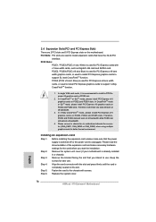
... card. Before installing the expansion card, please make necessary hardware settings for the card before you intend to install expansion cards that the power supply is switched off or the power cord is recommended to motherboard chassis fan connector (CHA_FAN1, CHA_FAN2 or CHA_FAN3) when using multiple graphics cards for later use . PCIE Slots...
... card. Before installing the expansion card, please make necessary hardware settings for the card before you intend to install expansion cards that the power supply is switched off or the power cord is recommended to motherboard chassis fan connector (CHA_FAN1, CHA_FAN2 or CHA_FAN3) when using multiple graphics cards for later use . PCIE Slots...

User Manual
Page 30
...short pin2 and pin3 on CLRCMOS1 for 15 seconds, use a jumper cap to default setup, please turn of f the computer and unplug the power cord from the power supply. Jumper Setting Clear CMOS Jumper (CLRCMOS1) (see p.12, No. 19) Default Clear CMOS Note: CLRCMOS1 allows you to clear the ...is "Short". When the jumper cap is placed on pins, the jumper is "Open". However, please do the clear-CMOS action. The Clear CMOS Switch has the same function as system password, date, time, and system setup parameters. 2.9 Jumpers Setup The illustration shows how jumpers are "Short" when ...
...short pin2 and pin3 on CLRCMOS1 for 15 seconds, use a jumper cap to default setup, please turn of f the computer and unplug the power cord from the power supply. Jumper Setting Clear CMOS Jumper (CLRCMOS1) (see p.12, No. 19) Default Clear CMOS Note: CLRCMOS1 allows you to clear the ...is "Short". When the jumper cap is placed on pins, the jumper is "Open". However, please do the clear-CMOS action. The Clear CMOS Switch has the same function as system password, date, time, and system setup parameters. 2.9 Jumpers Setup The illustration shows how jumpers are "Short" when ...
User Manual
Page 33
...Windows® 7 / 7 64-bit / VistaTM / VistaTM 64-bit OS: Go to connect them for HD audio panel only. PLED (System Power LED): Connect to the power switch on when the hard drive is operating. The LED keeps blinking when the sys-tem is in S3/S4 sleep state or... To activate the front mic. Then click "FrontMic". Connect the power switch, reset switch and system status indicator on when the system is reading or writing data. 33 RESET (Reset Switch): Connect to install your system using the power switch. The LED is on the chassis to this header according to MIC2_L...
...Windows® 7 / 7 64-bit / VistaTM / VistaTM 64-bit OS: Go to connect them for HD audio panel only. PLED (System Power LED): Connect to the power switch on when the hard drive is operating. The LED keeps blinking when the sys-tem is in S3/S4 sleep state or... To activate the front mic. Then click "FrontMic". Connect the power switch, reset switch and system status indicator on when the system is reading or writing data. 33 RESET (Reset Switch): Connect to install your system using the power switch. The LED is on the chassis to this header according to MIC2_L...

User Manual
Page 34
... match the black wire to the ground pin. A front panel module mainly consists of power switch, reset switch, power LED, hard drive activity LED, speaker and etc. The LED is operating. Please connect the chassis power LED to indicate system power status. When connecting your chassis front panel module to this header to this header, make...
... match the black wire to the ground pin. A front panel module mainly consists of power switch, reset switch, power LED, hard drive activity LED, speaker and etc. The LED is operating. Please connect the chassis power LED to indicate system power status. When connecting your chassis front panel module to this header to this header, make...
User Manual
Page 36
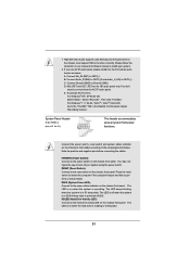
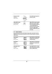
... to this header. 2.11 Smart Switches This motherboard has three smart switches: power switch, reset switch and clear CMOS switch, allowing users to connect HDMI Digital TV/ projector/LCD devices. Clear CMOS Switch (CLRCBTN) (see p.12 No. 22) Reset Switch is a smart switch, allowing users to quickly turn on... /off or reset the system or clear the CMOS values. Reset Switch (RSTBTN) (see p.13 No. 14) Clear CMOS Switch is a smart switch, allowing users to quickly reset the system. Power Switch (PWRBTN) (see p.12 No.31) This COM1 header supports a serial port ...
... to this header. 2.11 Smart Switches This motherboard has three smart switches: power switch, reset switch and clear CMOS switch, allowing users to connect HDMI Digital TV/ projector/LCD devices. Clear CMOS Switch (CLRCBTN) (see p.12 No. 22) Reset Switch is a smart switch, allowing users to quickly turn on... /off or reset the system or clear the CMOS values. Reset Switch (RSTBTN) (see p.13 No. 14) Clear CMOS Switch is a smart switch, allowing users to quickly reset the system. Power Switch (PWRBTN) (see p.12 No.31) This COM1 header supports a serial port ...

Quick Installation Guide
Page 2
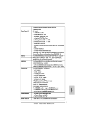
...Power Connector (ATXPWR1) 32 Infrared Module Header (IR1) 11 USB 3.0 Header (USB_12_13, Blue) 33 HDMI_SPDIF Header 12 Northbridge Controller (HDMI_SPDIF1, White) 13 Southbridge Controller 34 PCI Express 2.0 x16 Slot (PCIE5; White) 21 System Panel Header (PANEL1, White) 42 Front Panel Audio Header 22 Reset Switch (RSTBTN) (HD_AUDIO1, White) English 2 ASRock 970 Extreme4...24 23 22 21 20 11 12 13 14 15 16 17 18 19 1 ATX 12V Power Connector (ATX12V1) 23 Power Switch (PWRBTN) 2 Power Fan Connector (PWR_FAN1) 24 Front Panel IEEE 1394 Header 3 CPU Fan Connector (CPU_FAN2) (...
...Power Connector (ATXPWR1) 32 Infrared Module Header (IR1) 11 USB 3.0 Header (USB_12_13, Blue) 33 HDMI_SPDIF Header 12 Northbridge Controller (HDMI_SPDIF1, White) 13 Southbridge Controller 34 PCI Express 2.0 x16 Slot (PCIE5; White) 21 System Panel Header (PANEL1, White) 42 Front Panel Audio Header 22 Reset Switch (RSTBTN) (HD_AUDIO1, White) English 2 ASRock 970 Extreme4...24 23 22 21 20 11 12 13 14 15 16 17 18 19 1 ATX 12V Power Connector (ATX12V1) 23 Power Switch (PWRBTN) 2 Power Fan Connector (PWR_FAN1) 24 Front Panel IEEE 1394 Header 3 CPU Fan Connector (CPU_FAN2) (...
Quick Installation Guide
Page 7
... connector - 24 pin ATX power connector - 8 pin 12V power connector - HD Audio Jack: Side Speaker/Rear Speaker/Central/Bass/ Line in/Front Speaker/Microphone (see CAUTION 6) SATA3 - 5 x SATA3 ... 1394 Port - 1 x Clear CMOS Switch with GUI support English 7 ASRock 970 Extreme4 Motherboard Front panel audio connector - 3 x USB 2.0 headers (support 6 USB 2.0 ports) - 1 x USB 3.0 header (supports 2 USB 3.0 ports) - 1 x Dr. Debug (7-Segment Debug LED) Smart Switch - 1 x Clear CMOS Switch with LED - 1 x Power Switch with LED - 1 x Reset Switch with LED BIOS Feature - 32Mb AMI UEFI...
... connector - 24 pin ATX power connector - 8 pin 12V power connector - HD Audio Jack: Side Speaker/Rear Speaker/Central/Bass/ Line in/Front Speaker/Microphone (see CAUTION 6) SATA3 - 5 x SATA3 ... 1394 Port - 1 x Clear CMOS Switch with GUI support English 7 ASRock 970 Extreme4 Motherboard Front panel audio connector - 3 x USB 2.0 headers (support 6 USB 2.0 ports) - 1 x USB 3.0 header (supports 2 USB 3.0 ports) - 1 x Dr. Debug (7-Segment Debug LED) Smart Switch - 1 x Clear CMOS Switch with LED - 1 x Power Switch with LED - 1 x Reset Switch with LED BIOS Feature - 32Mb AMI UEFI...

Quick Installation Guide
Page 12
...! Doing so may cause severe damage to do so may damage the motherboard. 12 ASRock 970 Extreme4 Motherboard English Failure to the motherboard, peripherals, and/or components. 1. Before you uninstall any component, ensure that the power is switched off or the power cord is an ATX form factor (12.0-in x 9.6-in the bag that the motherboard...
...! Doing so may cause severe damage to do so may damage the motherboard. 12 ASRock 970 Extreme4 Motherboard English Failure to the motherboard, peripherals, and/or components. 1. Before you uninstall any component, ensure that the power is switched off or the power cord is an ATX form factor (12.0-in x 9.6-in the bag that the motherboard...
Quick Installation Guide
Page 16
... is used for better thermal environment. Remove the bracket facing the slot that you start the installation. Step 4. Replace the system cover. 16 ASRock 970 Extreme4 Motherboard English PCI Slots: PCI slots are 2 PCI slots and 5 PCI Express slots on PCIE2 slot. 2. In CrossFireXTM or SLITM mode, ... x16 graphics cards on PCIE2 and PCIE4 slots. Please read the documentation of the expansion card and make sure that the power supply is switched off or the power cord is already installed in a chassis). Fasten the card to install a PCI Express x16 graphics card on this motherboard...
... is used for better thermal environment. Remove the bracket facing the slot that you start the installation. Step 4. Replace the system cover. 16 ASRock 970 Extreme4 Motherboard English PCI Slots: PCI slots are 2 PCI slots and 5 PCI Express slots on PCIE2 slot. 2. In CrossFireXTM or SLITM mode, ... x16 graphics cards on PCIE2 and PCIE4 slots. Please read the documentation of the expansion card and make sure that the power supply is switched off or the power cord is already installed in a chassis). Fasten the card to install a PCI Express x16 graphics card on this motherboard...

Quick Installation Guide
Page 27
... on CLRCMOS1 for 15 seconds, use a jumper cap to clear the data in CMOS. English 27 ASRock 970 Extreme4 Motherboard The illustration shows a 3-pin jumper whose pin1 and pin2 are setup. Jumper Clear CMOS Jumper ...CLRCMOS1 allows you need to default setup, please turn off the computer and unplug the power cord from the power supply. Please be noted that the password, date, time, user default profile...pins. If no jumper cap is placed on pins, the jumper is "Short". The Clear CMOS Switch has the same function as the Clear CMOS jumper. After waiting for 5 seconds. However, please ...
... on CLRCMOS1 for 15 seconds, use a jumper cap to clear the data in CMOS. English 27 ASRock 970 Extreme4 Motherboard The illustration shows a 3-pin jumper whose pin1 and pin2 are setup. Jumper Clear CMOS Jumper ...CLRCMOS1 allows you need to default setup, please turn off the computer and unplug the power cord from the power supply. Please be noted that the password, date, time, user default profile...pins. If no jumper cap is placed on pins, the jumper is "Short". The Clear CMOS Switch has the same function as the Clear CMOS jumper. After waiting for 5 seconds. However, please ...

Quick Installation Guide
Page 30
...XP / XP 64-bit OS: Select "Mixer". Adjust "Recording Volume". RESET (Reset Switch): Connect to the hard drive activity LED on the chassis front panel. The LED is reading or writing data. 30 ASRock 970 Extreme4 Motherboard English For Windows® 7 / 7 64-bit / VistaTM / VistaTM 64... A. System Panel Header (9-pin PANEL1) (see p.2 No. 21) This header accommodates several system front panel functions. Connect the power switch, reset switch and system status indicator on the chassis front panel. Note the positive and negative pins before connecting the cables. Please follow the ...
...XP / XP 64-bit OS: Select "Mixer". Adjust "Recording Volume". RESET (Reset Switch): Connect to the hard drive activity LED on the chassis front panel. The LED is reading or writing data. 30 ASRock 970 Extreme4 Motherboard English For Windows® 7 / 7 64-bit / VistaTM / VistaTM 64... A. System Panel Header (9-pin PANEL1) (see p.2 No. 21) This header accommodates several system front panel functions. Connect the power switch, reset switch and system status indicator on the chassis front panel. Note the positive and negative pins before connecting the cables. Please follow the ...

Quick Installation Guide
Page 31
...front panel design may differ by chassis. A front panel module mainly consists of power switch, reset switch, power LED, hard drive activity LED, speaker and etc. The LED is on when the system is off ). Chassis and Power Fan Connectors (4-pin CHA_FAN1) (see p.2 No. 9) GND +12V CHA_FAN_SPEED ...(4-pin SPEAKER 1) (see p.2 No. 20) 1 SPEAKER DUMMY +5V DUMMY Power LED Header (3-pin PLED1) (see p.2 No. 18) Please connect the chassis speaker to this header to this header. English 31 ASRock 970 Extreme4 Motherboard CPU Fan Connectors (4-pin CPU_FAN1) (see p.2 No. 2) +12V GND ...
...front panel design may differ by chassis. A front panel module mainly consists of power switch, reset switch, power LED, hard drive activity LED, speaker and etc. The LED is on when the system is off ). Chassis and Power Fan Connectors (4-pin CHA_FAN1) (see p.2 No. 9) GND +12V CHA_FAN_SPEED ...(4-pin SPEAKER 1) (see p.2 No. 20) 1 SPEAKER DUMMY +5V DUMMY Power LED Header (3-pin PLED1) (see p.2 No. 18) Please connect the chassis speaker to this header to this header. English 31 ASRock 970 Extreme4 Motherboard CPU Fan Connectors (4-pin CPU_FAN1) (see p.2 No. 2) +12V GND ...

Quick Installation Guide
Page 34
...) (see p.3 No. 14) Clear CMOS Switch is a smart switch, allowing users to quickly clear the CMOS values English 34 ASRock 970 Extreme4 Motherboard Reset Switch (RSTBTN) (see p.2 No. 23) Power Switch is a smart switch, allowing users to quickly turn on /off the system. 2.11 Smart Switches This motherboard has three smart switches: power switch, reset switch and clear CMOS switch, allowing users to quickly turn...
...) (see p.3 No. 14) Clear CMOS Switch is a smart switch, allowing users to quickly clear the CMOS values English 34 ASRock 970 Extreme4 Motherboard Reset Switch (RSTBTN) (see p.2 No. 23) Power Switch is a smart switch, allowing users to quickly turn on /off the system. 2.11 Smart Switches This motherboard has three smart switches: power switch, reset switch and clear CMOS switch, allowing users to quickly turn...


