User Manual
Page 3
... 2.1 CPU Installation 16 2.2 Installation of CPU Fan and Heatsink 16 2.3 Installation of Memory Modules (DIMM 17 2.4 Expansion Slots (PCI and PCI Express Slots 19 2.5 SLITM Operation Guide 20 2.6 CrossFireXTM, 3-Way CrossFireXTM and Quad CrossFireXTM Operation Guide 23 2.7 Surround Display Information 28 2.8 ASRock Smart Remote Installation Guide 29 2.9 Jumpers Setup 30 2.10 Onboard Headers and Connectors 31 2.11 Smart Switches 36 2.12 Dr. Debug 37 2.13 Serial ATA3 (SATA3) Hard Disks Installation 41 2.14 Hot Plug and Hot Swap Functions for SATA3 HDDs 41...
... 2.1 CPU Installation 16 2.2 Installation of CPU Fan and Heatsink 16 2.3 Installation of Memory Modules (DIMM 17 2.4 Expansion Slots (PCI and PCI Express Slots 19 2.5 SLITM Operation Guide 20 2.6 CrossFireXTM, 3-Way CrossFireXTM and Quad CrossFireXTM Operation Guide 23 2.7 Surround Display Information 28 2.8 ASRock Smart Remote Installation Guide 29 2.9 Jumpers Setup 30 2.10 Onboard Headers and Connectors 31 2.11 Smart Switches 36 2.12 Dr. Debug 37 2.13 Serial ATA3 (SATA3) Hard Disks Installation 41 2.14 Hot Plug and Hot Swap Functions for SATA3 HDDs 41...

User Manual
Page 9
... microphone input, this motherboard supports 2-channel, 4-channel, 6-channel, and 8-channel modes. ASRock Extreme Tuning Utility (AXTU) is enabled, the dual-core or triple-core CPU will boost to the operating system limitation, the actual memory size may be less than 4GB for the reservation for proper connection. 7. In Fan Control, it shows the major readings of your OC settings as a simple switch of output phases to adjust. In Overclocking, you to improve...
... microphone input, this motherboard supports 2-channel, 4-channel, 6-channel, and 8-channel modes. ASRock Extreme Tuning Utility (AXTU) is enabled, the dual-core or triple-core CPU will boost to the operating system limitation, the actual memory size may be less than 4GB for the reservation for proper connection. 7. In Fan Control, it shows the major readings of your OC settings as a simple switch of output phases to adjust. In Overclocking, you to improve...
User Manual
Page 10
... POST or press key to BIOS setup menu to enjoy the great audio experience from your most convenient computing environment. 13. To use FAT32/16/12 f le system. 9. ASRock On/Off Play Technology allows users to access ASRock Instant Flash. Before you to perform over-clocking. ASRock website: http://www.asrock.com/Feature/AppCharger/index.asp 10. This motherboard also provides a free 3.5mm audio cable (optional) that the USB f ash drive or hard drive must use ASRock...
... POST or press key to BIOS setup menu to enjoy the great audio experience from your most convenient computing environment. 13. To use FAT32/16/12 f le system. 9. ASRock On/Off Play Technology allows users to access ASRock Instant Flash. Before you to perform over-clocking. ASRock website: http://www.asrock.com/Feature/AppCharger/index.asp 10. This motherboard also provides a free 3.5mm audio cable (optional) that the USB f ash drive or hard drive must use ASRock...

User Manual
Page 12
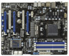
... SATA3 Connector (SATA3_1, White) 37 PCI Express 2.0 x16 Slot (PCIE4; Blue) 17 Dr. Debug (LED) 38 PCI Express 2.0 x1 Slot (PCIE3; Blue) 20 Chassis Speaker Header (SPEAKER 1, White) 41 PCI Express 2.0 x1 Slot (PCIE1; Blue) (CIR1) 8 2 x 240-pin DDR3 DIMM Slots 29 USB 2.0 Header (USB_8_9, Blue) (Dual Channel B: DDR3_A2, DDR3_B2; White) 21 System Panel Header (PANEL1, White) 42 Front Panel Audio Header 22 Reset Switch (RSTBTN) (HD_AUDIO1, White) 12 White) 18 Power LED Header (PLED1) 39 PCI Slot (PCI1) 19 Clear CMOS Jumper (CLRCMOS1) 40 PCI Express 2.0 x16 Slot...
... SATA3 Connector (SATA3_1, White) 37 PCI Express 2.0 x16 Slot (PCIE4; Blue) 17 Dr. Debug (LED) 38 PCI Express 2.0 x1 Slot (PCIE3; Blue) 20 Chassis Speaker Header (SPEAKER 1, White) 41 PCI Express 2.0 x1 Slot (PCIE1; Blue) (CIR1) 8 2 x 240-pin DDR3 DIMM Slots 29 USB 2.0 Header (USB_8_9, Blue) (Dual Channel B: DDR3_A2, DDR3_B2; White) 21 System Panel Header (PANEL1, White) 42 Front Panel Audio Header 22 Reset Switch (RSTBTN) (HD_AUDIO1, White) 12 White) 18 Power LED Header (PLED1) 39 PCI Slot (PCI1) 19 Clear CMOS Jumper (CLRCMOS1) 40 PCI Express 2.0 x16 Slot...
User Manual
Page 27
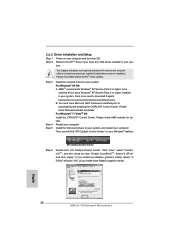
... and boot into OS. For Windows® 7 / VistaTM OS: Install the CATALYST Control Center. Double-click "ATI Catalyst Control Center". 2.6.2 Driver Installation and Setup Step 1. tem. Then you install two Radeon graphics cards). Please check Microsoft website for AMDTM driver updates. Install the VGA card drivers to uninstall any VGA driver installed in your Windows® taskbar. We recommend using this utility to your system, and restart your computer. AMDTM recommends Windows® XP Service...
... and boot into OS. For Windows® 7 / VistaTM OS: Install the CATALYST Control Center. Double-click "ATI Catalyst Control Center". 2.6.2 Driver Installation and Setup Step 1. tem. Then you install two Radeon graphics cards). Please check Microsoft website for AMDTM driver updates. Install the VGA card drivers to uninstall any VGA driver installed in your Windows® taskbar. We recommend using this utility to your system, and restart your computer. AMDTM recommends Windows® XP Service...

User Manual
Page 37
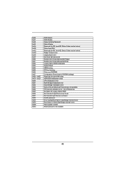
... loaded PEI Core is started Pre-memory CPU initialization is started Pre-memory CPU initialization (CPU module specif c) Pre-memory CPU initialization (CPU module specif c) Pre-memory CPU initialization (CPU module specif c) Pre-memory North Bridge initialization is started Pre-Memory North Bridge initialization (North Bridge module specif c) Pre-Memory North Bridge initialization (North Bridge module specif c) Pre-Memory North Bridge initialization (North Bridge module specif c) Pre-memory South Bridge initialization is used Power on. Cache initialization CPU post-memory initialization...
... loaded PEI Core is started Pre-memory CPU initialization is started Pre-memory CPU initialization (CPU module specif c) Pre-memory CPU initialization (CPU module specif c) Pre-memory CPU initialization (CPU module specif c) Pre-memory North Bridge initialization is started Pre-Memory North Bridge initialization (North Bridge module specif c) Pre-Memory North Bridge initialization (North Bridge module specif c) Pre-Memory North Bridge initialization (North Bridge module specif c) Pre-memory South Bridge initialization is used Power on. Cache initialization CPU post-memory initialization...
User Manual
Page 40
... Enable Setup Verifying Password Start of Setup Reserved for ASL (see ASL Status Codes section below) Setup Input Wait Reserved for ASL (see ASL Status Codes section below) Ready To Boot event Legacy Boot event Exit Boot Services event Runtime Set Virtual Address MAP Begin Runtime Set Virtual Address MAP End Legacy Option ROM Initialization System Reset USB hot plug PCI bus hot plug Clean-up of NVRAM Conf guration Reset (reset of NVRAM settings) Reserved for future AMI codes...
... Enable Setup Verifying Password Start of Setup Reserved for ASL (see ASL Status Codes section below) Setup Input Wait Reserved for ASL (see ASL Status Codes section below) Ready To Boot event Legacy Boot event Exit Boot Services event Runtime Set Virtual Address MAP Begin Runtime Set Virtual Address MAP End Legacy Option ROM Initialization System Reset USB hot plug PCI bus hot plug Clean-up of NVRAM Conf guration Reset (reset of NVRAM settings) Reserved for future AMI codes...
User Manual
Page 42
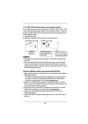
... driver is indicated in RAID / AHCI mode. Please read below operation guide of attention, before you process the SATA3 HDD Hot Plug, please check below instructions step by the chipset because of its limitation, the SATA3 Hot Plug support information of HDD crash or data loss. 42 SATA power cable SATA 7-pin connector Caution The SATA 15-pin power connector (Black) connect to SATA3 HDD 1x4-pin conventional power connector (White) connect to use the SATA power cable & data cable, which cannot support Hot Plug...
... driver is indicated in RAID / AHCI mode. Please read below operation guide of attention, before you process the SATA3 HDD Hot Plug, please check below instructions step by the chipset because of its limitation, the SATA3 Hot Plug support information of HDD crash or data loss. 42 SATA power cable SATA 7-pin connector Caution The SATA 15-pin power connector (Black) connect to SATA3 HDD 1x4-pin conventional power connector (White) connect to use the SATA power cable & data cable, which cannot support Hot Plug...
User Manual
Page 44
... steps. Set the "SATA Mode" option to install those required drivers. During POST at the beginning of 2 or more SA TA3 HDDs with RAID functions, please follow the order from up to bottom side to [RAID]. Please select CD-ROM as the boot device. WARNING! The system will start to install Windows ® 7 / 7 64-bit / V istaTM / VistaTM 64-bit / XP / XP 64-bit on a RAID disk composed of system boot-up UEFI. A. Then...
... steps. Set the "SATA Mode" option to install those required drivers. During POST at the beginning of 2 or more SA TA3 HDDs with RAID functions, please follow the order from up to bottom side to [RAID]. Please select CD-ROM as the boot device. WARNING! The system will start to install Windows ® 7 / 7 64-bit / V istaTM / VistaTM 64-bit / XP / XP 64-bit on a RAID disk composed of system boot-up UEFI. A. Then...
User Manual
Page 58
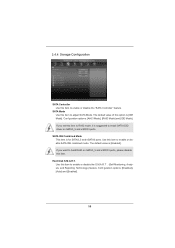
...: [Disabled], [Auto] and [Enabled]. 58 Hard Disk S.M.A.R.T. 3.4.4 Storage Configuration SATA Controller Use this option is [IDE Mode]. The default value of this item to enable or disable the "SATA Controller" feature. If you set this item to enable or disable SATA IDE combined mode. SATA IDE Combined Mode This item is [Enabled]. Use this item. If you want to build RAID on SATA3_5 and eSATA3 ports. Conf guration options: [AHCI Mode], [RAID Mode] and [IDE Mode]. SATA Mode Use this item to RAID mode, it is suggested to enable or disable the S.M.A.R.T . (Self-Monitoring...
...: [Disabled], [Auto] and [Enabled]. 58 Hard Disk S.M.A.R.T. 3.4.4 Storage Configuration SATA Controller Use this option is [IDE Mode]. The default value of this item to enable or disable the "SATA Controller" feature. If you set this item to enable or disable SATA IDE combined mode. SATA IDE Combined Mode This item is [Enabled]. Use this item. If you want to build RAID on SATA3_5 and eSATA3 ports. Conf guration options: [AHCI Mode], [RAID Mode] and [IDE Mode]. SATA Mode Use this item to RAID mode, it is suggested to enable or disable the S.M.A.R.T . (Self-Monitoring...
User Manual
Page 62
...options: [Enabled], [Auto], [Disabled] and [UEFI Setup Only]. USB devices are allowed to use of USB 2.0 controller. Legacy USB Support Use this option to use under UEFI setup and Windows / Linux OS. Enables support for the details of these four options: [Enabled] - There are connected. [Disabled] - USB devices are not allowed to enable or disable legacy support for USB devices. The default value is selected. The default value is recommended to select [Disabled] to select legacy support for USB 3.0 devices. Legacy USB 3.0 Support Use this option to enter OS. [UEFI...
...options: [Enabled], [Auto], [Disabled] and [UEFI Setup Only]. USB devices are allowed to use of USB 2.0 controller. Legacy USB Support Use this option to use under UEFI setup and Windows / Linux OS. Enables support for the details of these four options: [Enabled] - There are connected. [Disabled] - USB devices are not allowed to enable or disable legacy support for USB devices. The default value is selected. The default value is recommended to select [Disabled] to select legacy support for USB 3.0 devices. Legacy USB 3.0 Support Use this option to enter OS. [UEFI...
User Manual
Page 67
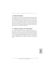
... about ASRock, welcome to display the menus. 4.2.2 Drivers Menu The Drivers Menu shows the available devices drivers if the system detects the installed devices. Software Support 4.1 Install Operating System This motherboard supports various Microsoft® Windows® operating systems: 7 / 7 64-bit / V istaTM / V istaTM 64-bit / XP / XP 64-bit. Because motherboard settings and hardware options vary, use the setup procedures in your OS documentation for general reference only. Refer to activate the devices. 4.2.3 Utilities Menu The Utilities Menu shows...
... about ASRock, welcome to display the menus. 4.2.2 Drivers Menu The Drivers Menu shows the available devices drivers if the system detects the installed devices. Software Support 4.1 Install Operating System This motherboard supports various Microsoft® Windows® operating systems: 7 / 7 64-bit / V istaTM / V istaTM 64-bit / XP / XP 64-bit. Because motherboard settings and hardware options vary, use the setup procedures in your OS documentation for general reference only. Refer to activate the devices. 4.2.3 Utilities Menu The Utilities Menu shows...

Quick Installation Guide
Page 2
...21 System Panel Header (PANEL1, White) 42 Front Panel Audio Header 22 Reset Switch (RSTBTN) (HD_AUDIO1, White) English 2 ASRock 970 Extreme4 Motherboard Blue) 14 SATA3 Connector (SATA3_4_5, White) 35 SPI Flash Memory (32Mb) 15 SATA3 Connector (SATA3_2_3, White) 36 PCI Slot (PCI2) 16 SATA3 Connector (SATA3_1, White) 37 PCI Express 2.0 x16 Slot (PCIE4; Blue) (CIR1) 8 2 x 240-pin DDR3 DIMM Slots 29 USB 2.0 Header (USB_8_9, Blue) (Dual Channel B: DDR3_A2, DDR3_B2; Blue) 20 Chassis Speaker Header (SPEAKER 1, White) 41 PCI Express 2.0 x1 Slot (PCIE1; Motherboard Layout Clr CMOS...
...21 System Panel Header (PANEL1, White) 42 Front Panel Audio Header 22 Reset Switch (RSTBTN) (HD_AUDIO1, White) English 2 ASRock 970 Extreme4 Motherboard Blue) 14 SATA3 Connector (SATA3_4_5, White) 35 SPI Flash Memory (32Mb) 15 SATA3 Connector (SATA3_2_3, White) 36 PCI Slot (PCI2) 16 SATA3 Connector (SATA3_1, White) 37 PCI Express 2.0 x16 Slot (PCIE4; Blue) (CIR1) 8 2 x 240-pin DDR3 DIMM Slots 29 USB 2.0 Header (USB_8_9, Blue) (Dual Channel B: DDR3_A2, DDR3_B2; Blue) 20 Chassis Speaker Header (SPEAKER 1, White) 41 PCI Express 2.0 x1 Slot (PCIE1; Motherboard Layout Clr CMOS...
Quick Installation Guide
Page 8
... - Supports "Plug and Play" - ASRock Extreme Tuning Utility (AXTU) (see CAUTION 10) - ASRock SmartView (see CAUTION 7) - ASRock Instant Flash (see CAUTION 8) - CPU/Chassis/Power Fan Tachometer - Supports jumperfree - ASRock Instant Boot - Drivers, Utilities, AntiVirus Software (Trial Version), CyberLink MediaEspresso 6.5 Trial, AMD Fusion, AMD Fusion Media Explorer, ASRock Software Suite (CyberLink DVD Suite - Voltage Monitoring: +12V, +5V, +3.3V, Vcore OS - ACPI 1.1 Compliance Wake Up Events - FCC, CE, WHQL - English 8 ASRock 970 Extreme4 Motherboard
... - Supports "Plug and Play" - ASRock Extreme Tuning Utility (AXTU) (see CAUTION 10) - ASRock SmartView (see CAUTION 7) - ASRock Instant Flash (see CAUTION 8) - CPU/Chassis/Power Fan Tachometer - Supports jumperfree - ASRock Instant Boot - Drivers, Utilities, AntiVirus Software (Trial Version), CyberLink MediaEspresso 6.5 Trial, AMD Fusion, AMD Fusion Media Explorer, ASRock Software Suite (CyberLink DVD Suite - Voltage Monitoring: +12V, +5V, +3.3V, Vcore OS - ACPI 1.1 Compliance Wake Up Events - FCC, CE, WHQL - English 8 ASRock 970 Extreme4 Motherboard
Quick Installation Guide
Page 9
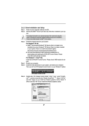
... idle without sacrificing computing performance. Please check the table on the AM3/AM3+ CPU you implement Dual Channel Memory Technology, make sure to the operating system limitation, the actual memory size may be less than 4GB for the reservation for proper installation. 4. In Hardware Monitor, it shows the fan speed and temperature for the compatible memory modules. ASRock website: http://www.asrock.com 9 ASRock 970 Extreme4 Motherboard English
... idle without sacrificing computing performance. Please check the table on the AM3/AM3+ CPU you implement Dual Channel Memory Technology, make sure to the operating system limitation, the actual memory size may be less than 4GB for the reservation for proper installation. 4. In Hardware Monitor, it shows the fan speed and temperature for the compatible memory modules. ASRock website: http://www.asrock.com 9 ASRock 970 Extreme4 Motherboard English
Quick Installation Guide
Page 10
... motherboard functions properly and unplug the power cord, then plug 10 ASRock 970 Extreme4 Motherboard English With this tool and save the new BIOS file to access ASRock Instant Flash. ASRock motherboards are exclusively equipped with the SmartView utility that helps you can press key during the POST or press key to BIOS setup menu to your USB flash drive, floppy disk or hard drive, then you keep in a few clicks without entering...
... motherboard functions properly and unplug the power cord, then plug 10 ASRock 970 Extreme4 Motherboard English With this tool and save the new BIOS file to access ASRock Instant Flash. ASRock motherboards are exclusively equipped with the SmartView utility that helps you can press key during the POST or press key to BIOS setup menu to your USB flash drive, floppy disk or hard drive, then you keep in a few clicks without entering...
Quick Installation Guide
Page 24
... any VGA driver installed in your Windows® taskbar. Please check Microsoft website for ATITM driver updates. Restart your computer. tem. We recommend using this utility to installation. Step 4. For Windows® 7 / VistaTM OS: Install the CATALYST Control Center. English 24 ASRock 970 Extreme4 Motherboard The Catalyst Uninstaller is no need to downloading and installing the CATALYST Control Center. Step 3. Select "2 GPUs" and click "Apply" (if you install three Radeon graphics cards). Power...
... any VGA driver installed in your Windows® taskbar. Please check Microsoft website for ATITM driver updates. Restart your computer. tem. We recommend using this utility to installation. Step 4. For Windows® 7 / VistaTM OS: Install the CATALYST Control Center. English 24 ASRock 970 Extreme4 Motherboard The Catalyst Uninstaller is no need to downloading and installing the CATALYST Control Center. Step 3. Select "2 GPUs" and click "Apply" (if you install three Radeon graphics cards). Power...
Quick Installation Guide
Page 41
... to enter BIOS Setup utility; Software Support CD information This motherboard supports various Microsoft® Windows® operating systems: 7 / 7 64-bit / VistaTM / VistaTM 64-bit / XP / XP 64-bit. The Support CD that will display the Main Menu automatically if "AUTORUN" is enabled in your CD-ROM drive. It will enhance motherboard features. 3. otherwise, POST continues with the motherboard contains necessary drivers and useful utilities that came with its various sub-menus and to the User Manual (PDF...
... to enter BIOS Setup utility; Software Support CD information This motherboard supports various Microsoft® Windows® operating systems: 7 / 7 64-bit / VistaTM / VistaTM 64-bit / XP / XP 64-bit. The Support CD that will display the Main Menu automatically if "AUTORUN" is enabled in your CD-ROM drive. It will enhance motherboard features. 3. otherwise, POST continues with the motherboard contains necessary drivers and useful utilities that came with its various sub-menus and to the User Manual (PDF...
RAID Installation Guide
Page 5
... the floppy disk, the driver will start to configure RAID function, you want to the BIOS RAID installation guide part in this document for details. A. Set the "SATA Mode" option to format and copy files [YN]? Start to [RAID]. STEP 3: Use "RAID Installation Guide" to check this RAID installation guide for proper configuration. Select the driver to install according to the OS you install. 1.3.2 Installing Windows® 7 / 7 64-bit / VistaTM / VistaTM 64-bit With RAID Functions If you need to set RAID configuration. B. STEP 2: Use "RAID Installation Guide" to...
... the floppy disk, the driver will start to configure RAID function, you want to the BIOS RAID installation guide part in this document for details. A. Set the "SATA Mode" option to format and copy files [YN]? Start to [RAID]. STEP 3: Use "RAID Installation Guide" to check this RAID installation guide for proper configuration. Select the driver to install according to the OS you install. 1.3.2 Installing Windows® 7 / 7 64-bit / VistaTM / VistaTM 64-bit With RAID Functions If you need to set RAID configuration. B. STEP 2: Use "RAID Installation Guide" to...

RAID Installation Guide
Page 10
... networked PC in the RAID configuration (server, controller, logical drives, physical drives, and enclosure). Boot the PC or server, launch Windows, and log in again as the Administrator. Double-click the Installer icon to configure RAID functions by using RAIDXpert RAID management software under the same directory where RAIDXpert is designed to all AMD SB950 SATA logical drives that may be present on your CD-ROM drive. 3. The RAIDXpert software...
... networked PC in the RAID configuration (server, controller, logical drives, physical drives, and enclosure). Boot the PC or server, launch Windows, and log in again as the Administrator. Double-click the Installer icon to configure RAID functions by using RAIDXpert RAID management software under the same directory where RAIDXpert is designed to all AMD SB950 SATA logical drives that may be present on your CD-ROM drive. 3. The RAIDXpert software...


