
User Manual
Page 3
Installation 14 Pre-installation Precautions 14 2.1 CPU Installation 15 2.2 Installation of CPU Fan and Heatsink 15 2.3 Installation of Memory Modules (DIMM 16 2.4 Expansion Slots (PCI and PCI Express Slots 18 2.5 Dual Monitor and Surround Display Features 19 2.6 ATITM Hybrid CrossFireXTM Operation Guide 22 2.7 Jumpers Setup 24 2.8 Onboard Headers and Connectors 25 2.9 SATAII ...
Installation 14 Pre-installation Precautions 14 2.1 CPU Installation 15 2.2 Installation of CPU Fan and Heatsink 15 2.3 Installation of Memory Modules (DIMM 16 2.4 Expansion Slots (PCI and PCI Express Slots 18 2.5 Dual Monitor and Surround Display Features 19 2.6 ATITM Hybrid CrossFireXTM Operation Guide 22 2.7 Jumpers Setup 24 2.8 Onboard Headers and Connectors 25 2.9 SATAII ...

User Manual
Page 6
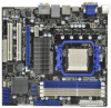
...: D-Sub, DVI-D and HDMI - resolution up to 1920x1200 (1080P) - Six-Core CPU Ready - Dual Channel DDR3 Memory Technology (see CAUTION 4) - 1 x PCI Express 2.0 x16 slot (blue @ x16 mode) - 1 x PCI Express 2.0 x1 slot - 2 x PCI slots - Supports HDCP function with ACC feature (Advanced Clock Calibration) - All Solid Capacitor design (100% Japan-made high-quality Polymer Capacitors...
...: D-Sub, DVI-D and HDMI - resolution up to 1920x1200 (1080P) - Six-Core CPU Ready - Dual Channel DDR3 Memory Technology (see CAUTION 4) - 1 x PCI Express 2.0 x16 slot (blue @ x16 mode) - 1 x PCI Express 2.0 x1 slot - 2 x PCI slots - Supports HDCP function with ACC feature (Advanced Clock Calibration) - All Solid Capacitor design (100% Japan-made high-quality Polymer Capacitors...

User Manual
Page 18
...: PCIE1 (PCIE x1 slot; Installing an expansion card Step 1. Step 2. Step 4. Step 5. 2.4 Expansion Slots (PCI and PCI Express Slots) There are used to use . PCI Slots: PCI slots are 2 PCI slots and 2 PCI Express slots on the slot. Remove the system unit cover (if your motherboard is used for later use . Step ... lane width graphics cards. Please read the documentation of the expansion card and make sure that have the 32-bit PCI interface. Keep the screws for PCI Express cards with screws. Fasten the card to the chassis with x1 lane width cards, such as Gigabit LAN card...
...: PCIE1 (PCIE x1 slot; Installing an expansion card Step 1. Step 2. Step 4. Step 5. 2.4 Expansion Slots (PCI and PCI Express Slots) There are used to use . PCI Slots: PCI slots are 2 PCI slots and 2 PCI Express slots on the slot. Remove the system unit cover (if your motherboard is used for later use . Step ... lane width graphics cards. Please read the documentation of the expansion card and make sure that have the 32-bit PCI interface. Keep the screws for PCI Express cards with screws. Fasten the card to the chassis with x1 lane width cards, such as Gigabit LAN card...

User Manual
Page 20
...my Windows desktop onto this motherboard. 4. E. If you do not adjust the BIOS setup, the default value of the add-on PCI Express VGA card on PCI Express VGA card driver to your system. Click the "Identify" button to the corresponding connectors of "Share Memory", [Auto], will be...C through E for the diaplay icon identified by the number 2. Surround Display Feature This motherboard supports surround display upgrade. Install the ATITM PCI Express VGA card on VGA card is less than the total capability of surround display feature. Then connect other monitor cables to display ...
...my Windows desktop onto this motherboard. 4. E. If you do not adjust the BIOS setup, the default value of the add-on PCI Express VGA card on PCI Express VGA card driver to your system. Click the "Identify" button to the corresponding connectors of "Share Memory", [Auto], will be...C through E for the diaplay icon identified by the number 2. Surround Display Feature This motherboard supports surround display upgrade. Install the ATITM PCI Express VGA card on VGA card is less than the total capability of surround display feature. Then connect other monitor cables to display ...

User Manual
Page 22
... AX3450 256MD2-S ATI RADEON HD5450 1GB Driver Support CD 8.70 Support CD 8.70 Support CD 8.70 Enjoy the benefit of more compatible PCI Express graphics cards, please visit our website for ATITM Hybrid CrossFireXTM. Then set the option "Surround View" to enter BIOS setup. Step... refer to PCIE2 slot (blue). Please visit our website for both the onboard VGA and the discrete graphics card. Install one compatible PCI Express graphics card to section "Expansion Slots". 2.6 ATITM Hybrid CrossFireXTM Operation Guide This motherboard supports ATITM Hybrid CrossFireXTM feature. ATITM Hybrid ...
... AX3450 256MD2-S ATI RADEON HD5450 1GB Driver Support CD 8.70 Support CD 8.70 Support CD 8.70 Enjoy the benefit of more compatible PCI Express graphics cards, please visit our website for ATITM Hybrid CrossFireXTM. Then set the option "Surround View" to enter BIOS setup. Step... refer to PCIE2 slot (blue). Please visit our website for both the onboard VGA and the discrete graphics card. Install one compatible PCI Express graphics card to section "Expansion Slots". 2.6 ATITM Hybrid CrossFireXTM Operation Guide This motherboard supports ATITM Hybrid CrossFireXTM feature. ATITM Hybrid ...

User Manual
Page 38
Before you apply Untied Overclocking Technology. 38 2.16 Untied Overclocking Technology This motherboard supports Untied Overclocking Technology, which means during overclocking, but PCI / PCIE buses are in the fixed mode so that FSB can operate under a more stable overclocking environment. Therefore, CPU FSB is untied during overclocking, FSB ... possible overclocking risk before you enable Untied Overclocking function, please enter "Overclock Mode" option of BIOS setup to set the selection from [Auto] to fixed PCI / PCIE buses.
Before you apply Untied Overclocking Technology. 38 2.16 Untied Overclocking Technology This motherboard supports Untied Overclocking Technology, which means during overclocking, but PCI / PCIE buses are in the fixed mode so that FSB can operate under a more stable overclocking environment. Therefore, CPU FSB is untied during overclocking, FSB ... possible overclocking risk before you enable Untied Overclocking function, please enter "Overclock Mode" option of BIOS setup to set the selection from [Auto] to fixed PCI / PCIE buses.

User Manual
Page 51
... Audio Select [Auto], [Enabled] or [Disabled] for video card. Primary Graphics Adapter This item will be disabled when PCI Sound Card is [PCI]. Internal Graphics Mode This allows you to select the type of Primary VGA in AMD 890GX. Share Memory This allows you...[Auto]. 3.4.2 Chipset Configuration BIOS SETUP UTILITY Advanced Chipset Settings Onboard HD Audio Front Panel OnBoard Lan Primary Graphics Adapter [Auto] [Auto] [Enabled] [PCI] Internal Graphics Mode Share Memory Onboard HDMI HD Audio Surround View [UMA] [Auto] [Disabled] [Disabled] Options UMA Disabled +F1 F9 F10 ESC ...
... Audio Select [Auto], [Enabled] or [Disabled] for video card. Primary Graphics Adapter This item will be disabled when PCI Sound Card is [PCI]. Internal Graphics Mode This allows you to select the type of Primary VGA in AMD 890GX. Share Memory This allows you...[Auto]. 3.4.2 Chipset Configuration BIOS SETUP UTILITY Advanced Chipset Settings Onboard HD Audio Front Panel OnBoard Lan Primary Graphics Adapter [Auto] [Auto] [Enabled] [PCI] Internal Graphics Mode Share Memory Onboard HDMI HD Audio Surround View [UMA] [Auto] [Disabled] [Disabled] Options UMA Disabled +F1 F9 F10 ESC ...

User Manual
Page 52
... to enable or disable PS/2 keyboard to turn on the system from the power-soft-off mode. PCI Devices Power On Use this option to [Enabled] if you to auto-detect or disable the Suspend...Suspend to RAM Use this item to select whether to set this item to enable or disable PCI devices to power on the system from the power-soft-off when the power recovers. Restore on... AC / Power Loss Ring-In Power On PCI Devices Power On PS / 2 Keyboard Power On RTC Alarm Power On ACPI HPET Table [Auto] [Auto] [Disabled]...
... to enable or disable PS/2 keyboard to turn on the system from the power-soft-off mode. PCI Devices Power On Use this option to [Enabled] if you to auto-detect or disable the Suspend...Suspend to RAM Use this item to select whether to set this item to enable or disable PCI devices to power on the system from the power-soft-off when the power recovers. Restore on... AC / Power Loss Ring-In Power On PCI Devices Power On PS / 2 Keyboard Power On RTC Alarm Power On ACPI HPET Table [Auto] [Auto] [Disabled]...

User Manual
Page 55
...Floppy Configuration Floppy A [1.44 MB 312"] Select the type of floppy drive connected to malfunction. Setting wrong values in units of PCI clocks for PCI device latency timer register. +F1 F9 F10 ESC Select Screen Select Item Change Option General Help Load Defaults Save and Exit Exit ...v02.54 (C) Copyright 1985-2003, American Megatrends, Inc. PCI Latency Timer The default value is recommended to enable or disable the PCI IDE BusMaster feature. 3.4.6 Floppy Configuration In this section, you may cause the system to the system. ...
...Floppy Configuration Floppy A [1.44 MB 312"] Select the type of floppy drive connected to malfunction. Setting wrong values in units of PCI clocks for PCI device latency timer register. +F1 F9 F10 ESC Select Screen Select Item Change Option General Help Load Defaults Save and Exit Exit ...v02.54 (C) Copyright 1985-2003, American Megatrends, Inc. PCI Latency Timer The default value is recommended to enable or disable the PCI IDE BusMaster feature. 3.4.6 Floppy Configuration In this section, you may cause the system to the system. ...
Quick Installation Guide
Page 2
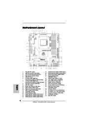
... Controller 17 SATAII Connector (SATAII_4 (PORT 3), Blue) 35 USB_PW2 Jumper 18 SATAII Connector (SATAII_3 (PORT 2), Blue) 2 ASRock 890GMH/USB3 Motherboard Blue) 14 Southbridge Controller 32 PCI Express 2.0 x1 Slot (PCIE1; White) 26 Floppy Connector (FLOPPY1) 8 ATX Power Connector (ATXPWR1) 27 Serial Port Connector...Panel Audio Header 11 USB 2.0 Header (USB6_7, Blue) (HD_AUDIO1, White) 12 Chassis Fan Connector (CHA_FAN1) 30 PCI Slots (PCI1-2) 13 USB 2.0 Header (USB8_9, Blue) 31 PCI Express 2.0 x16 Slot (PCIE2; Blue) 24 Clear CMOS Jumper (CLRCMOS1) 7 2 x 240-pin DDR3 DIMM...
... Controller 17 SATAII Connector (SATAII_4 (PORT 3), Blue) 35 USB_PW2 Jumper 18 SATAII Connector (SATAII_3 (PORT 2), Blue) 2 ASRock 890GMH/USB3 Motherboard Blue) 14 Southbridge Controller 32 PCI Express 2.0 x1 Slot (PCIE1; White) 26 Floppy Connector (FLOPPY1) 8 ATX Power Connector (ATXPWR1) 27 Serial Port Connector...Panel Audio Header 11 USB 2.0 Header (USB6_7, Blue) (HD_AUDIO1, White) 12 Chassis Fan Connector (CHA_FAN1) 30 PCI Slots (PCI1-2) 13 USB 2.0 Header (USB8_9, Blue) 31 PCI Express 2.0 x16 Slot (PCIE2; Blue) 24 Clear CMOS Jumper (CLRCMOS1) 7 2 x 240-pin DDR3 DIMM...

Quick Installation Guide
Page 5
...-buffered memory (see CAUTION 4) - 1 x PCI Express 2.0 x16 slot (blue @ x16 mode) - 1 x PCI Express 2.0 x1 slot - 2 x PCI slots - Max. capacity of system memory: 16GB (see CAUTION 3) - Integrated AMD Radeon HD 4290 graphics - Max. shared memory 512MB (see CAUTION 5) - resolution up to 2560x1600 @ 75Hz - Supports Dual-link DVI with DVI and HDMI ports English 5 ASRock 890GMH/USB3 Motherboard
...-buffered memory (see CAUTION 4) - 1 x PCI Express 2.0 x16 slot (blue @ x16 mode) - 1 x PCI Express 2.0 x1 slot - 2 x PCI slots - Max. capacity of system memory: 16GB (see CAUTION 3) - Integrated AMD Radeon HD 4290 graphics - Max. shared memory 512MB (see CAUTION 5) - resolution up to 2560x1600 @ 75Hz - Supports Dual-link DVI with DVI and HDMI ports English 5 ASRock 890GMH/USB3 Motherboard

Quick Installation Guide
Page 15
...card connector with the slot and press firmly until the card is completely seated on this motherboard. Replace the system cover. 15 ASRock 890GMH/USB3 Motherboard English Please read the documentation of the expansion card and make sure that the power supply is switched off or the power... the 32-bit PCI interface. Step 6. PCIE2 (PCIE x16 slot; PCI Slots: PCI slots are 2 PCI slots and 2 PCI Express slots on the slot. Blue) is used for PCI Express x16 lane width graphics cards. Step 3. 2.4 Expansion Slots (PCI and PCI Express Slots) There are used for PCI Express cards with ...
...card connector with the slot and press firmly until the card is completely seated on this motherboard. Replace the system cover. 15 ASRock 890GMH/USB3 Motherboard English Please read the documentation of the expansion card and make sure that the power supply is switched off or the power... the 32-bit PCI interface. Step 6. PCIE2 (PCIE x16 slot; PCI Slots: PCI slots are 2 PCI slots and 2 PCI Express slots on the slot. Blue) is used for PCI Express x16 lane width graphics cards. Step 3. 2.4 Expansion Slots (PCI and PCI Express Slots) There are used for PCI Express cards with ...

Quick Installation Guide
Page 17
... A. D. Right-click the display icon in the Display Properties dialog that you select is less than the total capability of the add-on PCI Express VGA card on the I /O panel, or connect HDMI monitor cable to enable the function of VGA/D-sub. Select the display icon identified...icon identified by the number 2. Then connect other monitor cables to the steps below. Boot your card, one , two, three and four. 17 ASRock 890GMH/USB3 Motherboard English For Windows® XP / XP 64-bit OS: Right click the desktop, choose "Properties", and select the "Settings" tab so that...
... A. D. Right-click the display icon in the Display Properties dialog that you select is less than the total capability of the add-on PCI Express VGA card on the I /O panel, or connect HDMI monitor cable to enable the function of VGA/D-sub. Select the display icon identified...icon identified by the number 2. Then connect other monitor cables to the steps below. Boot your card, one , two, three and four. 17 ASRock 890GMH/USB3 Motherboard English For Windows® XP / XP 64-bit OS: Right click the desktop, choose "Properties", and select the "Settings" tab so that...

Quick Installation Guide
Page 19
...AX3450 256MD2-S ATI RADEON HD5450 1GB Driver Support CD 8.70 Support CD 8.70 Support CD 8.70 Enjoy the benefit of more compatible PCI Express graphics cards, please visit our website for further information. Then you have any VGA driver installed in a Windows® VistaTM ... Step 1. Install one compatible PCI Express graphics card to your system for blisteringlyfast frame rates. Step 3. Boot your Windows® taskbar. Install the onboard VGA driver from our support CD to PCIE2 slot (blue). Step 6. English ATI Catalyst Control Center 19 ASRock 890GMH/USB3 Motherboard
...AX3450 256MD2-S ATI RADEON HD5450 1GB Driver Support CD 8.70 Support CD 8.70 Support CD 8.70 Enjoy the benefit of more compatible PCI Express graphics cards, please visit our website for further information. Then you have any VGA driver installed in a Windows® VistaTM ... Step 1. Install one compatible PCI Express graphics card to your system for blisteringlyfast frame rates. Step 3. Boot your Windows® taskbar. Install the onboard VGA driver from our support CD to PCIE2 slot (blue). Step 6. English ATI Catalyst Control Center 19 ASRock 890GMH/USB3 Motherboard

Quick Installation Guide
Page 27
... Hot Plug functions (AHCI mode) STEP 1: Set Up BIOS. B. Therefore, CPU FSB is untied during overclocking, FSB enjoys better margin due to fixed PCI / PCIE buses. A. STEP 2: Install Windows® 7 / 7 64-bit / VistaTM / VistaTM 64-bit OS on your system. STEP 2: ... supports Untied Overclocking Technology, which means during overclocking, but PCI / PCIE buses are in the fixed mode so that FSB can operate under a more stable overclocking environment. English 27 ASRock 890GMH/USB3 Motherboard Enter BIOS SETUP UTILITY Advanced screen Storage Configuration. Before...
... Hot Plug functions (AHCI mode) STEP 1: Set Up BIOS. B. Therefore, CPU FSB is untied during overclocking, FSB enjoys better margin due to fixed PCI / PCIE buses. A. STEP 2: Install Windows® 7 / 7 64-bit / VistaTM / VistaTM 64-bit OS on your system. STEP 2: ... supports Untied Overclocking Technology, which means during overclocking, but PCI / PCIE buses are in the fixed mode so that FSB can operate under a more stable overclocking environment. English 27 ASRock 890GMH/USB3 Motherboard Enter BIOS SETUP UTILITY Advanced screen Storage Configuration. Before...
