
User Manual
Page 4
... 3.4 Advanced Screen 49 3.4.1 CPU Configuration 50 3.4.2 Chipset Configuration 51 3.4.3 ACPI Configuration 52 3.4.4 Storage Configuration 53 3.4.5 PCIPnP Configuration 55 3.4.6 Floppy Configuration 55 3.4.7 Super IO Configuration 56 3.4.8 USB Configuration 57 3.5 Hardware Health Event Monitoring Screen 58 3.6 Boot Screen 59 3.6.1 Boot Settings Configuration 59 3.7 Security Screen 60 3.8 Exit Screen 61 4 . Software Support 62 4.1 Install...
... 3.4 Advanced Screen 49 3.4.1 CPU Configuration 50 3.4.2 Chipset Configuration 51 3.4.3 ACPI Configuration 52 3.4.4 Storage Configuration 53 3.4.5 PCIPnP Configuration 55 3.4.6 Floppy Configuration 55 3.4.7 Super IO Configuration 56 3.4.8 USB Configuration 57 3.5 Hardware Health Event Monitoring Screen 58 3.6 Boot Screen 59 3.6.1 Boot Settings Configuration 59 3.7 Security Screen 60 3.8 Exit Screen 61 4 . Software Support 62 4.1 Install...

User Manual
Page 7
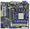
... Audio Jack: Rear Speaker/Central/Bass/Line in header - CD in / Front Speaker/Microphone (see CAUTION 6) - 1 x USB 3.0 port by Fresco FL1000G, supports USB 3.0 up to -Use USB 3.0 Port - 1 x RJ-45 LAN Port with Content Protection (Realtek ALC892 Audio Codec) - ACPI 1.1 Compliance Wake Up ... Panel - 1 x PS/2 Keyboard Port - 1 x VGA/D-Sub Port - 1 x VGA/DVI-D Port - 1 x HDMI Port - 1 x Optical SPDIF Out Port - 5 x Ready-to-Use USB 2.0 Ports - 1 x eSATAII Connector - 1 x Ready-to 5Gb/s - 5 x Serial ATAII 3.0Gb/s connectors, support RAID (RAID 0, RAID 1, RAID 10 and JBOD), NCQ, AHCI and "Hot Plug...
... Audio Jack: Rear Speaker/Central/Bass/Line in header - CD in / Front Speaker/Microphone (see CAUTION 6) - 1 x USB 3.0 port by Fresco FL1000G, supports USB 3.0 up to -Use USB 3.0 Port - 1 x RJ-45 LAN Port with Content Protection (Realtek ALC892 Audio Codec) - ACPI 1.1 Compliance Wake Up ... Panel - 1 x PS/2 Keyboard Port - 1 x VGA/D-Sub Port - 1 x VGA/DVI-D Port - 1 x HDMI Port - 1 x Optical SPDIF Out Port - 5 x Ready-to-Use USB 2.0 Ports - 1 x eSATAII Connector - 1 x Ready-to 5Gb/s - 5 x Serial ATAII 3.0Gb/s connectors, support RAID (RAID 0, RAID 1, RAID 10 and JBOD), NCQ, AHCI and "Hot Plug...

User Manual
Page 10
...of. Please be noticed that the USB flash drive or hard drive must use FAT32/16/12 file system. 11. ASRock AIWI is just to install the ASRock AIWI utility either from ASRock official website or ASRock software support CD to 40% faster than before. ASRock APP Charger. Simply installing the ...also download the free AIWI Lite from your iPhone/iPod touch. It helps you to save your OC settings as yours! ASRock website: http://www.asrock.com/Feature/AppCharger/index.asp 14. This convenient BIOS update tool allows you to update system BIOS without preparing an additional ...
...of. Please be noticed that the USB flash drive or hard drive must use FAT32/16/12 file system. 11. ASRock AIWI is just to install the ASRock AIWI utility either from ASRock official website or ASRock software support CD to 40% faster than before. ASRock APP Charger. Simply installing the ...also download the free AIWI Lite from your iPhone/iPod touch. It helps you to save your OC settings as yours! ASRock website: http://www.asrock.com/Feature/AppCharger/index.asp 14. This convenient BIOS update tool allows you to update system BIOS without preparing an additional ...
User Manual
Page 13
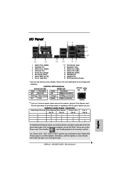
...Mixer ToolBox" , click "Enable playback multi-streaming", and click "ok". 1.4 I/O Panel 1 2 34 58 69 7 10 16 15 14 13 12 11 1 USB 2.0 Ports (USB23) 2 VGA/D-Sub Port 3 USB 2.0 Ports (USB45) * 4 LAN RJ-45 Port 5 Central / Bass (Orange) 6 Rear Speaker (Black) 7 Optical SPDIF Out Port 8 Line In (Light ...Blue) ** 9 Front Speaker (Lime) 10 Microphone (Pink) 11 USB 2.0 Port (USB0) 12 USB 3.0 Port (USB1) 13 eSATAII Port (eSATA1) 14 VGA/HDMI Port 15 VGA/DVI-D Port 16 PS/2 Keyboard Port (Purple) * There are allowed ...
...Mixer ToolBox" , click "Enable playback multi-streaming", and click "ok". 1.4 I/O Panel 1 2 34 58 69 7 10 16 15 14 13 12 11 1 USB 2.0 Ports (USB23) 2 VGA/D-Sub Port 3 USB 2.0 Ports (USB45) * 4 LAN RJ-45 Port 5 Central / Bass (Orange) 6 Rear Speaker (Black) 7 Optical SPDIF Out Port 8 Line In (Light ...Blue) ** 9 Front Speaker (Lime) 10 Microphone (Pink) 11 USB 2.0 Port (USB0) 12 USB 3.0 Port (USB1) 13 eSATAII Port (eSATA1) 14 VGA/HDMI Port 15 VGA/DVI-D Port 16 PS/2 Keyboard Port (Purple) * There are allowed ...
User Manual
Page 24
... If you need to clear the CMOS when you just finish updating the BIOS, you do not clear the CMOS right after you select +5V_DUAL, USB devices can wake up the system first, and then shut it requires 2 Amp and higher standby current provided by power supply. When you update the...
... If you need to clear the CMOS when you just finish updating the BIOS, you do not clear the CMOS right after you select +5V_DUAL, USB devices can wake up the system first, and then shut it requires 2 Amp and higher standby current provided by power supply. When you update the...

User Manual
Page 26
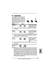
... header as a CD-ROM, DVD-ROM, TV tuner card, or MPEG card. Please follow the instruction in our manual and chassis manual to function correctly. USB 2.0 Headers (9-pin USB6_7) (see p.12 No. 11) (9-pin USB8_9) (see p.12 No. 13) (9-pin USB10_11) (see p.12 No. 23) Infrared... P-8 USB_PWR USB_PWR P-11 P+11 GND DUMMY 1 GND P+10 P-10 USB_PWR IRTX +5V DUMMY 1 GND IRRX Besides five default USB 2.0 ports on the I/O panel, there are three USB 2.0 headers on the chassis must support HDA to install your system. 2. This header supports an optional wireless transmitting and receiving infrared module...
... header as a CD-ROM, DVD-ROM, TV tuner card, or MPEG card. Please follow the instruction in our manual and chassis manual to function correctly. USB 2.0 Headers (9-pin USB6_7) (see p.12 No. 11) (9-pin USB8_9) (see p.12 No. 13) (9-pin USB10_11) (see p.12 No. 23) Infrared... P-8 USB_PWR USB_PWR P-11 P+11 GND DUMMY 1 GND P+10 P-10 USB_PWR IRTX +5V DUMMY 1 GND IRRX Besides five default USB 2.0 ports on the I/O panel, there are three USB 2.0 headers on the chassis must support HDA to install your system. 2. This header supports an optional wireless transmitting and receiving infrared module...
User Manual
Page 49
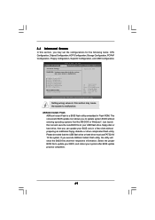
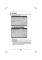
... Inc. If you to malfunction. CPU Configuration Chipset Configuration ACPI Configuration Storage Configuration PCIPnP Configuration Floppy Configuration SuperIO Configuration USB Configuration BIOS Update Utility ASRock Instant Flash Select Screen Select Item Enter Go to update your BIOS, and reboot your BIOS only in this section... may cause the system to your USB flash drive, floppy disk or hard drive, then you may cause system ...
... Inc. If you to malfunction. CPU Configuration Chipset Configuration ACPI Configuration Storage Configuration PCIPnP Configuration Floppy Configuration SuperIO Configuration USB Configuration BIOS Update Utility ASRock Instant Flash Select Screen Select Item Enter Go to update your BIOS, and reboot your BIOS only in this section... may cause the system to your USB flash drive, floppy disk or hard drive, then you may cause system ...

User Manual
Page 57
... BIOS setup when [Disabled] is recommended to select [Disabled] to enable or disable the USB 2.0 support. 3.4.8 USB Configuration BIOS SETUP UTILITY Advanced USB Configuration USB Controller USB 2.0 Support Legacy USB Support USB 3.0 Controller [Enabled] [Enabled] [Enabled] [Enabled] To enable or disable the onboard USB controllers. +F1 F9 F10 ESC Select Screen Select Item Change Option General Help Load...
... BIOS setup when [Disabled] is recommended to select [Disabled] to enable or disable the USB 2.0 support. 3.4.8 USB Configuration BIOS SETUP UTILITY Advanced USB Configuration USB Controller USB 2.0 Support Legacy USB Support USB 3.0 Controller [Enabled] [Enabled] [Enabled] [Enabled] To enable or disable the onboard USB controllers. +F1 F9 F10 ESC Select Screen Select Item Change Option General Help Load...
User Manual
Page 59
... Item Change Option General Help Load Defaults Save and Exit Exit v02.54 (C) Copyright 1985-2003, American Megatrends, Inc. Configuration options: [Enabled] and [Disabled]. ROM C] [USB] Select Screen Select Item Enter Go to adjust AddOn ROM Display. HDS722580VL] [CD / DVD: 3S - The default value is [Enabled]. 59 3.6 Boot Screen In this...
... Item Change Option General Help Load Defaults Save and Exit Exit v02.54 (C) Copyright 1985-2003, American Megatrends, Inc. Configuration options: [Enabled] and [Disabled]. ROM C] [USB] Select Screen Select Item Enter Go to adjust AddOn ROM Display. HDS722580VL] [CD / DVD: 3S - The default value is [Enabled]. 59 3.6 Boot Screen In this...
Quick Installation Guide
Page 2
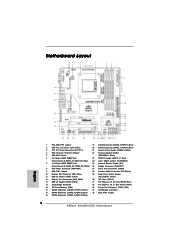
... 10 Primary IDE Connector (IDE1, Blue) 29 Front Panel Audio Header 11 USB 2.0 Header (USB6_7, Blue) (HD_AUDIO1, White) 12 Chassis Fan Connector (CHA_FAN1) 30 PCI Slots (PCI1-2) 13 USB 2.0 Header (USB8_9, Blue) 31 PCI Express 2.0 x16 Slot (PCIE2; ...White) 15 SPI Flash Memory (8Mb) 33 Power Fan Connector (PWR_FAN1) 16 SATAII Connector (SATAII_5 (PORT 4), Blue) 34 Northbridge Controller 17 SATAII Connector (SATAII_4 (PORT 3), Blue) 35 USB_PW2 Jumper 18 SATAII Connector (SATAII_3 (PORT 2), Blue) 2 ASRock 890GMH/USB3...
... 10 Primary IDE Connector (IDE1, Blue) 29 Front Panel Audio Header 11 USB 2.0 Header (USB6_7, Blue) (HD_AUDIO1, White) 12 Chassis Fan Connector (CHA_FAN1) 30 PCI Slots (PCI1-2) 13 USB 2.0 Header (USB8_9, Blue) 31 PCI Express 2.0 x16 Slot (PCIE2; ...White) 15 SPI Flash Memory (8Mb) 33 Power Fan Connector (PWR_FAN1) 16 SATAII Connector (SATAII_5 (PORT 4), Blue) 34 Northbridge Controller 17 SATAII Connector (SATAII_4 (PORT 3), Blue) 35 USB_PW2 Jumper 18 SATAII Connector (SATAII_3 (PORT 2), Blue) 2 ASRock 890GMH/USB3...
Quick Installation Guide
Page 3
...Orange) 6 Rear Speaker (Black) 7 Optical SPDIF Out Port 8 Line In (Light Blue) ** 9 Front Speaker (Lime) 10 Microphone (Pink) 11 USB 2.0 Port (USB0) 12 USB 3.0 Port (USB1) 13 eSATAII Port (eSATA1) 14 VGA/HDMI Port 15 VGA/DVI-D Port 16 PS/2 Keyboard Port (Purple) * There are allowed ...to select "Realtek HDA Primary output" to use Rear Speaker, Central/Bass, and Front Speaker, or select "Realtek HDA Audio 2nd output" to use front panel audio. 3 ASRock 890GMH/USB3...
...Orange) 6 Rear Speaker (Black) 7 Optical SPDIF Out Port 8 Line In (Light Blue) ** 9 Front Speaker (Lime) 10 Microphone (Pink) 11 USB 2.0 Port (USB0) 12 USB 3.0 Port (USB1) 13 eSATAII Port (eSATA1) 14 VGA/HDMI Port 15 VGA/DVI-D Port 16 PS/2 Keyboard Port (Purple) * There are allowed ...to select "Realtek HDA Primary output" to use Rear Speaker, Central/Bass, and Front Speaker, or select "Realtek HDA Audio 2nd output" to use front panel audio. 3 ASRock 890GMH/USB3...

Quick Installation Guide
Page 6
... Play" - VCCM, NB, SB Voltage Multi-adjustment English 6 ASRock 890GMH/USB3 Motherboard PCIE x1 Gigabit LAN 10/100/1000 Mb/s - Supports jumperfree - Audio LAN Rear Panel I /O Panel - 1 x PS/2 Keyboard Port - 1 x VGA/D-Sub Port - 1 x VGA/DVI-D Port - 1 x HDMI Port - 1 x Optical SPDIF Out Port - 5 x Ready-to-Use USB 2.0 Ports - 1 x eSATAII Connector - 1 x Ready-to 5Gb/s - 5 x Serial ATAII...
... Play" - VCCM, NB, SB Voltage Multi-adjustment English 6 ASRock 890GMH/USB3 Motherboard PCIE x1 Gigabit LAN 10/100/1000 Mb/s - Supports jumperfree - Audio LAN Rear Panel I /O Panel - 1 x PS/2 Keyboard Port - 1 x VGA/D-Sub Port - 1 x VGA/DVI-D Port - 1 x HDMI Port - 1 x Optical SPDIF Out Port - 5 x Ready-to-Use USB 2.0 Ports - 1 x eSATAII Connector - 1 x Ready-to 5Gb/s - 5 x Serial ATAII...

Quick Installation Guide
Page 9
...turn your overclocking record under the operating system and simplifies the complicated recording process of the system or damage the CPU. 9 ASRock 890GMH/USB3 Motherboard English ASRock AIWI is a BIOS flash utility embedded in a few clicks without entering operating systems first like MS-DOS or Windows®....the new BIOS file to perform over-clocking. 10. Frequencies other complicated flash utility. With this utility, you can update your USB flash drive, floppy disk or hard drive, then you can easily enjoy the marvelous charging experience than the recommended CPU bus ...
...turn your overclocking record under the operating system and simplifies the complicated recording process of the system or damage the CPU. 9 ASRock 890GMH/USB3 Motherboard English ASRock AIWI is a BIOS flash utility embedded in a few clicks without entering operating systems first like MS-DOS or Windows®....the new BIOS file to perform over-clocking. 10. Frequencies other complicated flash utility. With this utility, you can update your USB flash drive, floppy disk or hard drive, then you can easily enjoy the marvelous charging experience than the recommended CPU bus ...
Quick Installation Guide
Page 21
...jumper whose pin1 and pin2 are setup. Note: To select +5VSB, it down before you do not clear the CMOS right after you select +5V_DUAL, USB devices can wake up events. Clear CMOS Jumper (CLRCMOS1) (see p.2, No. 1) +5VSB (standby) for 5 seconds. The data in CMOS. ...No. 35) +5V_DUAL for USB6_7/8_9/10_11 wake up events. After waiting for 15 seconds, use a jumper cap to RAM) state. English 21 ASRock 890GMH/USB3 Motherboard To clear and reset the system parameters to enable (see p.2, No. 24) Default Clear CMOS Note: CLRCMOS1 allows you must boot up events...
...jumper whose pin1 and pin2 are setup. Note: To select +5VSB, it down before you do not clear the CMOS right after you select +5V_DUAL, USB devices can wake up events. Clear CMOS Jumper (CLRCMOS1) (see p.2, No. 1) +5VSB (standby) for 5 seconds. The data in CMOS. ...No. 35) +5V_DUAL for USB6_7/8_9/10_11 wake up events. After waiting for 15 seconds, use a jumper cap to RAM) state. English 21 ASRock 890GMH/USB3 Motherboard To clear and reset the system parameters to enable (see p.2, No. 24) Default Clear CMOS Note: CLRCMOS1 allows you must boot up events...

Quick Installation Guide
Page 23
... CD1) (CD1: see p.2 No. 28) Front Panel Audio Header (9-pin HD_AUDIO1) (see p.2 No. 23) Besides five default USB 2.0 ports on the I/O panel, there are three USB 2.0 headers on the chassis must support HDA to the front panel audio header as a CD-ROM, DVD-ROM, TV tuner card,... supports Jack Sensing, but the panel wire on this motherboard. Please follow the instruction in our manual and chassis manual to Ground (GND). 23 ASRock 890GMH/USB3 Motherboard English Connect Ground (GND) to install your system. 2. Connect Mic_IN (MIC) to OUT2_L. Connect Audio_R (RIN) to OUT2_R and Audio_L ...
... CD1) (CD1: see p.2 No. 28) Front Panel Audio Header (9-pin HD_AUDIO1) (see p.2 No. 23) Besides five default USB 2.0 ports on the I/O panel, there are three USB 2.0 headers on the chassis must support HDA to the front panel audio header as a CD-ROM, DVD-ROM, TV tuner card,... supports Jack Sensing, but the panel wire on this motherboard. Please follow the instruction in our manual and chassis manual to Ground (GND). 23 ASRock 890GMH/USB3 Motherboard English Connect Ground (GND) to install your system. 2. Connect Mic_IN (MIC) to OUT2_L. Connect Audio_R (RIN) to OUT2_R and Audio_L ...


