RAID Installation Guide
Page 4
... install. (Select "AMD AHCI Compatible RAID Controller-x86 platform" for Windows XP, or "AMD AHCI Compatible RAID Controller-x64 platform" for details. 4 Enter BIOS SETUP UTILITY → Advanced screen →IDE Configuration. When you see these messages, Please insert a blank formatted diskette into floppy drive A: press any key. When prompted, insert the SATA / SATAII driver diskette containing AMD RAID driver. Then, please set RAID configuration. A. B. After making a SATA / SATAII driver diskette and set up "SATA Operation Mode" to generate Serial ATA driver diskette...
... install. (Select "AMD AHCI Compatible RAID Controller-x86 platform" for Windows XP, or "AMD AHCI Compatible RAID Controller-x64 platform" for details. 4 Enter BIOS SETUP UTILITY → Advanced screen →IDE Configuration. When you see these messages, Please insert a blank formatted diskette into floppy drive A: press any key. When prompted, insert the SATA / SATAII driver diskette containing AMD RAID driver. Then, please set RAID configuration. A. B. After making a SATA / SATAII driver diskette and set up "SATA Operation Mode" to generate Serial ATA driver diskette...
RAID Installation Guide
Page 5
...SATAII HDDs with the disk drives installed, the AMD onboard BIOS will display the following path in BIOS. 1.4 Create Disk Array Power on your system. page, please insert the ASRock Support CD into the optical drive to boot your system, and follow below steps. Then, please set RAID configuration. Set the "SATA Operation Mode" option to set the RAID configuration by using the Windows RAID installation guide in this RAID installation guide for details. Enter BIOS SETUP UTILITY → Advanced screen →IDE Configuration. STEP 2: Use "RAID Installation Guide" to [RAID...
...SATAII HDDs with the disk drives installed, the AMD onboard BIOS will display the following path in BIOS. 1.4 Create Disk Array Power on your system. page, please insert the ASRock Support CD into the optical drive to boot your system, and follow below steps. Then, please set RAID configuration. Set the "SATA Operation Mode" option to set the RAID configuration by using the Windows RAID installation guide in this RAID installation guide for details. Enter BIOS SETUP UTILITY → Advanced screen →IDE Configuration. STEP 2: Use "RAID Installation Guide" to [RAID...
RAID Installation Guide
Page 10
... software CD into your system. 2.2 Browser Support On the Host PC with the AMD SB710 SATA RAID Controller (the "Host PC"). 2. The RAIDXpert software offers local and remote management and monitoring of all programs. If you must use one of all components in again as the Administrator. RAIDXpert RAID management software: The RAIDXpert software installs on your CD-ROM drive. 3. Boot the PC or server, launch Windows...
... software CD into your system. 2.2 Browser Support On the Host PC with the AMD SB710 SATA RAID Controller (the "Host PC"). 2. The RAIDXpert software offers local and remote management and monitoring of all programs. If you must use one of all components in again as the Administrator. RAIDXpert RAID management software: The RAIDXpert software installs on your CD-ROM drive. 3. Boot the PC or server, launch Windows...
User Manual
Page 11
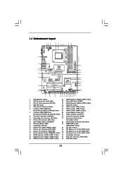
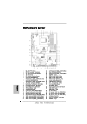
...) 29 Floppy Connector (FLOPPY1) 8 ATX Power Connector (ATXPWR1) 30 Serial Port Connector (COM1) 9 Northbridge Fan Connector (NB_FAN1) 31 Front Panel Audio Header 10 Primary IDE Connector (IDE1, Blue) (HD_AUDIO1, White) 11 Clear CMOS Jumper (CLRCMOS1) 32 Internal Audio Connector: CD1 (Black) 12 SPI Flash Memory (8Mb) 33 HDMI_SPDIF Header 13 Southbridge Controller (HDMI_SPDIF1, White) 14 System Panel Header (PANEL1, White) 34 PCI Slots (PCI1-3) 15 Chassis Fan Connector (CHA_FAN2) 35 PCI Express 2.0 x1 Slot (PCIE3; Blue) 27 USB 2.0 Header (USB10_11, Blue) 7 2 x 240-pin DDR3...
...) 29 Floppy Connector (FLOPPY1) 8 ATX Power Connector (ATXPWR1) 30 Serial Port Connector (COM1) 9 Northbridge Fan Connector (NB_FAN1) 31 Front Panel Audio Header 10 Primary IDE Connector (IDE1, Blue) (HD_AUDIO1, White) 11 Clear CMOS Jumper (CLRCMOS1) 32 Internal Audio Connector: CD1 (Black) 12 SPI Flash Memory (8Mb) 33 HDMI_SPDIF Header 13 Southbridge Controller (HDMI_SPDIF1, White) 14 System Panel Header (PANEL1, White) 34 PCI Slots (PCI1-3) 15 Chassis Fan Connector (CHA_FAN2) 35 PCI Express 2.0 x1 Slot (PCIE3; Blue) 27 USB 2.0 Header (USB10_11, Blue) 7 2 x 240-pin DDR3...

User Manual
Page 18
... motherboard supports dual monitor feature. If you can start to your system and restart your system boots. VGA/D-Sub port VGA/DVI-D port HDMI port 2. This motherboard also provides independent display controllers for DVI-D, D-Sub and HDMI to HDMI port on this motherboard. When one of them is enabled, the other one will be disabled. 2. With the internal VGA output support (DVI-D, D-Sub and HDMI), you haven't installed onboard VGA driver yet, please install onboard VGA driver from Blu-ray (BD) or HD-DVD...
... motherboard supports dual monitor feature. If you can start to your system and restart your system boots. VGA/D-Sub port VGA/DVI-D port HDMI port 2. This motherboard also provides independent display controllers for DVI-D, D-Sub and HDMI to HDMI port on this motherboard. When one of them is enabled, the other one will be disabled. 2. With the internal VGA output support (DVI-D, D-Sub and HDMI), you haven't installed onboard VGA driver yet, please install onboard VGA driver from Blu-ray (BD) or HD-DVD...

User Manual
Page 19
...". Then connect other monitor cables to the corresponding connectors of the multi-monitor according to enable the function of surround display feature. Please make sure that you do not adjust the BIOS setup, the default value of the system memory. B. G. Click "Apply" or "OK" to enter BIOS setup. Install the ATITM PCI Express VGA card on the I/O panel. Connect DVI-D monitor cable to VGA/DVI-D port on the I/O panel, connect D-Sub monitor cable to VGA/D-Sub port on the I/O panel, or connect HDMI monitor cable to display...
...". Then connect other monitor cables to the corresponding connectors of the multi-monitor according to enable the function of surround display feature. Please make sure that you do not adjust the BIOS setup, the default value of the system memory. B. G. Click "Apply" or "OK" to enter BIOS setup. Install the ATITM PCI Express VGA card on the I/O panel. Connect DVI-D monitor cable to VGA/DVI-D port on the I/O panel, connect D-Sub monitor cable to VGA/D-Sub port on the I/O panel, or connect HDMI monitor cable to display...

User Manual
Page 33
... below steps. The system will see the message on a RAID disk composed of system boot-up BIOS. Enter BIOS SETUP UTILITY Advanced screen Storage Configuration. E. Then, the drivers compatible to your system can work properly. 2.14 Installing Windows® 7 / 7 64-bit / VistaTM / VistaTM 64-bit / XP / XP 64-bit With RAID Functions If you want to [RAID]. Set the "SATA Operation Mode" option to install Windows® XP / XP 64-bit on the screen, "Generate Serial ATA driver diskette [YN]?", press . A.
... below steps. The system will see the message on a RAID disk composed of system boot-up BIOS. Enter BIOS SETUP UTILITY Advanced screen Storage Configuration. E. Then, the drivers compatible to your system can work properly. 2.14 Installing Windows® 7 / 7 64-bit / VistaTM / VistaTM 64-bit / XP / XP 64-bit With RAID Functions If you want to [RAID]. Set the "SATA Operation Mode" option to install Windows® XP / XP 64-bit on the screen, "Generate Serial ATA driver diskette [YN]?", press . A.

User Manual
Page 34
... RAID configuration. Enter BIOS SETUP UTILITY Advanced screen Storage Configuration. B. STEP 3: Use "RAID Installation Guide" to the BIOS RAID installation guide part of the document in the following path in the Support CD: .. \ RAID Installation Guide STEP 4: Install Windows® XP / XP 64-bit OS on your system. Please refer to set the RAID configuration by using the Windows RAID installation guide in the following path in the Support CD for Windows® XP 64-bit.) NOTE. After reading the floppy disk, the driver will be presented. STEP 2: Use "RAID Installation Guide...
... RAID configuration. Enter BIOS SETUP UTILITY Advanced screen Storage Configuration. B. STEP 3: Use "RAID Installation Guide" to the BIOS RAID installation guide part of the document in the following path in the Support CD: .. \ RAID Installation Guide STEP 4: Install Windows® XP / XP 64-bit OS on your system. Please refer to set the RAID configuration by using the Windows RAID installation guide in the following path in the Support CD for Windows® XP 64-bit.) NOTE. After reading the floppy disk, the driver will be presented. STEP 2: Use "RAID Installation Guide...
User Manual
Page 41
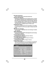
...The default value is [Disabled]. BIOS SETUP UTILITY Main OC Tweaker Advanced H/W Monitor Boot Security Exit Load Optimized CPU OC Setting [Press Enter] Load Optimized mGPU OC Setting [Press Enter] CPU Configuration Overclock Mode CPU Frequency (MHZ) PCIE Frequency (MHz) Spread Spectrum Boot Failure Guard Boot Failure Guard Count Advanced Clock Calibration CPU Active Core Control AMD Turbo Core Technology AMD IO C-State Support Processor Maximum Frequency North Bridge Maximum Frequency Processor Maximum Voltage Multiplier/Voltage Change [Auto] [200] [100] [Auto] [Enabled] [3] [Disabled...
...The default value is [Disabled]. BIOS SETUP UTILITY Main OC Tweaker Advanced H/W Monitor Boot Security Exit Load Optimized CPU OC Setting [Press Enter] Load Optimized mGPU OC Setting [Press Enter] CPU Configuration Overclock Mode CPU Frequency (MHZ) PCIE Frequency (MHz) Spread Spectrum Boot Failure Guard Boot Failure Guard Count Advanced Clock Calibration CPU Active Core Control AMD Turbo Core Technology AMD IO C-State Support Processor Maximum Frequency North Bridge Maximum Frequency Processor Maximum Voltage Multiplier/Voltage Change [Auto] [200] [100] [Auto] [Enabled] [3] [Disabled...
User Manual
Page 49
... compatibility issue with some memory modules or power supplies. Configuration options: [Auto], [Enabled] and [Disabled]. Please set to keep the CPU from the chipset. Secure Virtual Machine When this function may reduce CPU voltage and memory frequency, and lead to [Disable] if above issue occurs. Configuration options: [Enabled] and [Disabled]. Please note that enabling this option is [Auto]. 3.4.1 CPU Configuration Advanced CPU Configuration Cool 'n' Quiet Secure Virtual Machine Enhanced Halt State L3 Cache Allocation CPU Thermal Throttle BIOS SETUP UTILITY [Enabled...
... compatibility issue with some memory modules or power supplies. Configuration options: [Auto], [Enabled] and [Disabled]. Please set to keep the CPU from the chipset. Secure Virtual Machine When this function may reduce CPU voltage and memory frequency, and lead to [Disable] if above issue occurs. Configuration options: [Enabled] and [Disabled]. Please note that enabling this option is [Auto]. 3.4.1 CPU Configuration Advanced CPU Configuration Cool 'n' Quiet Secure Virtual Machine Enhanced Halt State L3 Cache Allocation CPU Thermal Throttle BIOS SETUP UTILITY [Enabled...
User Manual
Page 56
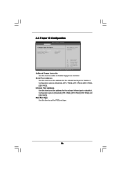
...the onboard serial port or disable it . 3.4.7 Super IO Configuration BIOS SETUP UTILITY Advanced Configure Super IO Chipset OnBoard Floppy Controller Serial Port Address Infrared Port Address PS/2 Port Type [Enabled] [3F8 / IRQ4] [Disabled] [Auto] Allow BIOS to set the address for the onboard infrared port or disable it . Configuration options: [Disabled], [3F8 / IRQ4], [2F8 / IRQ3], [3E8 / IRQ4] and [2E8 / IRQ3]. OnBoard Floppy Controller Use this item to Enable or Disable Floppy Controller. +F1 F9 F10 ESC Select Screen Select Item Change Option General Help Load Defaults Save...
...the onboard serial port or disable it . 3.4.7 Super IO Configuration BIOS SETUP UTILITY Advanced Configure Super IO Chipset OnBoard Floppy Controller Serial Port Address Infrared Port Address PS/2 Port Type [Enabled] [3F8 / IRQ4] [Disabled] [Auto] Allow BIOS to set the address for the onboard infrared port or disable it . Configuration options: [Disabled], [3F8 / IRQ4], [2F8 / IRQ3], [3E8 / IRQ4] and [2E8 / IRQ3]. OnBoard Floppy Controller Use this item to Enable or Disable Floppy Controller. +F1 F9 F10 ESC Select Screen Select Item Change Option General Help Load Defaults Save...
User Manual
Page 57
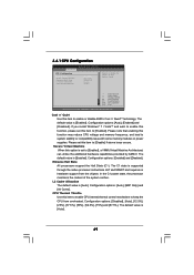
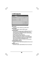
... you have USB compatibility issue, it is [Enabled]. Please refer to use under BIOS setup and Windows / Linux OS. 3.4.8 USB Configuration BIOS SETUP UTILITY Advanced USB Configuration USB Controller USB 2.0 Support Legacy USB Support [Enabled] [Enabled] [Enabled] USB Keyboard/Remote Power On [Disabled] USB Mouse Power On [Disabled] To enable or disable the onboard USB controllers. +F1 F9 F10 ESC Select Screen Select Item Change Option General Help Load Defaults Save and Exit Exit v02.54 (C) Copyright 1985-2003, American Megatrends, Inc. USB devices are connected. [Disabled] -
... you have USB compatibility issue, it is [Enabled]. Please refer to use under BIOS setup and Windows / Linux OS. 3.4.8 USB Configuration BIOS SETUP UTILITY Advanced USB Configuration USB Controller USB 2.0 Support Legacy USB Support [Enabled] [Enabled] [Enabled] USB Keyboard/Remote Power On [Disabled] USB Mouse Power On [Disabled] To enable or disable the onboard USB controllers. +F1 F9 F10 ESC Select Screen Select Item Change Option General Help Load Defaults Save and Exit Exit v02.54 (C) Copyright 1985-2003, American Megatrends, Inc. USB devices are connected. [Disabled] -

User Manual
Page 60
.../user password for the system. Select Screen Select Item Enter Change F1 General Help F9 Load Defaults F10 Save and Exit ESC Exit v02.54 (C) Copyright 1985-2005, American Megatrends, Inc. 60 BIOS SETUP UTILITY Main OC Tweaker Advanced H/W Monitor Boot Security Exit Security Settings Supervisor Password : Not Installed User Password : Not Installed Change Supervisor Password Change User Password Install or Change the password. Boot From Onboard LAN Use this item to select logo in POST screen. For the user password, you enable the option "Full Screen Logo". Boot...
.../user password for the system. Select Screen Select Item Enter Change F1 General Help F9 Load Defaults F10 Save and Exit ESC Exit v02.54 (C) Copyright 1985-2005, American Megatrends, Inc. 60 BIOS SETUP UTILITY Main OC Tweaker Advanced H/W Monitor Boot Security Exit Security Settings Supervisor Password : Not Installed User Password : Not Installed Change Supervisor Password Change User Password Install or Change the password. Boot From Onboard LAN Use this item to select logo in POST screen. For the user password, you enable the option "Full Screen Logo". Boot...

User Manual
Page 62
... CD-ROM drive. The CD automatically displays the Main Menu if "AUTORUN" is enabled in this chapter for further information. 62 Please install the necessary drivers to display the menus. 4.2.2 Drivers Menu The Drivers Menu shows the available devices drivers if the system detects the installed devices. Software Support 4.1 Install Operating System This motherboard supports various Microsoft® Windows® operating systems: 7 / 7 64-bit / VistaTM / VistaTM 64-bit / XP / XP 64-bit. Click on the file "ASSETUP...
... CD-ROM drive. The CD automatically displays the Main Menu if "AUTORUN" is enabled in this chapter for further information. 62 Please install the necessary drivers to display the menus. 4.2.2 Drivers Menu The Drivers Menu shows the available devices drivers if the system detects the installed devices. Software Support 4.1 Install Operating System This motherboard supports various Microsoft® Windows® operating systems: 7 / 7 64-bit / VistaTM / VistaTM 64-bit / XP / XP 64-bit. Click on the file "ASSETUP...
Quick Installation Guide
Page 2
...Jumper 2 ASRock 785G Pro Motherboard White) 29 Floppy Connector (FLOPPY1) 8 ATX Power Connector (ATXPWR1) 30 Serial Port Connector (COM1) 9 Northbridge Fan Connector (NB_FAN1) 31 Front Panel Audio Header 10 Primary IDE Connector (IDE1, Blue) (HD_AUDIO1, White) 11 Clear CMOS Jumper (CLRCMOS1) 32 Internal Audio Connector: CD1 (Black) 12 SPI Flash Memory (8Mb) 33 HDMI_SPDIF Header 13 Southbridge Controller (HDMI_SPDIF1, White) 14 System Panel Header (PANEL1, White) 34 PCI Slots (PCI1-3) 15 Chassis Fan Connector (CHA_FAN2) 35 PCI Express 2.0 x1 Slot (PCIE3; Blue) 27 USB 2.0 Header...
...Jumper 2 ASRock 785G Pro Motherboard White) 29 Floppy Connector (FLOPPY1) 8 ATX Power Connector (ATXPWR1) 30 Serial Port Connector (COM1) 9 Northbridge Fan Connector (NB_FAN1) 31 Front Panel Audio Header 10 Primary IDE Connector (IDE1, Blue) (HD_AUDIO1, White) 11 Clear CMOS Jumper (CLRCMOS1) 32 Internal Audio Connector: CD1 (Black) 12 SPI Flash Memory (8Mb) 33 HDMI_SPDIF Header 13 Southbridge Controller (HDMI_SPDIF1, White) 14 System Panel Header (PANEL1, White) 34 PCI Slots (PCI1-3) 15 Chassis Fan Connector (CHA_FAN2) 35 PCI Express 2.0 x1 Slot (PCIE3; Blue) 27 USB 2.0 Header...

Quick Installation Guide
Page 3
... (Pink) 11 USB 2.0 Ports (USB01) 12 eSATAII Port (eSATAII_1) 13 VGA/HDMI Port 14 VGA/DVI-D Port 15 PS/2 Keyboard Port (Purple) * There are allowed to select "Realtek HDA Primary output" to use 2-channel speaker, please connect the speaker's plug into "Front Speaker Jack". Choose "2CH", "4CH", "6CH", or "8CH" and then you will find "Mixer" tool on your computer, you are two LED next to use front panel audio. 3 ASRock 785G Pro Motherboard English
... (Pink) 11 USB 2.0 Ports (USB01) 12 eSATAII Port (eSATAII_1) 13 VGA/HDMI Port 14 VGA/DVI-D Port 15 PS/2 Keyboard Port (Purple) * There are allowed to select "Realtek HDA Primary output" to use 2-channel speaker, please connect the speaker's plug into "Front Speaker Jack". Choose "2CH", "4CH", "6CH", or "8CH" and then you will find "Mixer" tool on your computer, you are two LED next to use front panel audio. 3 ASRock 785G Pro Motherboard English
Quick Installation Guide
Page 9
... DNA literally tells you to your friends! The software name itself - With this utility, you checking with your USB flash drive, floppy disk or hard drive, then you can press key during the POST or press key to BIOS setup menu to record the OC settings and share with others. OC DNA, an exclusive utility developed by European Union to define the power consumption for the user to access ASRock Instant Flash.
... DNA literally tells you to your friends! The software name itself - With this utility, you checking with your USB flash drive, floppy disk or hard drive, then you can press key during the POST or press key to BIOS setup menu to record the OC settings and share with others. OC DNA, an exclusive utility developed by European Union to define the power consumption for the user to access ASRock Instant Flash.

Quick Installation Guide
Page 15
... of both monitors. 15 ASRock 785G Pro Motherboard English Then you can start to your computer. DVI-D and HDMI ports cannot function at the same time. If you have installed onboard VGA driver from our support CD to HDMI port on this motherboard. With the internal VGA output support (DVI-D, D-Sub and HDMI), you haven't installed onboard VGA driver yet, please install onboard VGA driver from our support CD to use dual monitor function on the I/O panel. When one will be disabled. 2. If you...
... of both monitors. 15 ASRock 785G Pro Motherboard English Then you can start to your computer. DVI-D and HDMI ports cannot function at the same time. If you have installed onboard VGA driver from our support CD to HDMI port on this motherboard. With the internal VGA output support (DVI-D, D-Sub and HDMI), you haven't installed onboard VGA driver yet, please install onboard VGA driver from our support CD to use dual monitor function on the I/O panel. When one will be disabled. 2. If you...

Quick Installation Guide
Page 25
... Storage Configuration. Set the "SATA Operation Mode" option to your optical drive first. Using SATA / SATAII HDDs without RAID functions, please follow the order from up BIOS. Please connect the HDMI_SPDIF connector of HDMI VGA card to this header. 2.9 Driver Installation Guide To install the drivers to your system, please insert the support CD to [IDE]. B. STEP 2: Install Windows® XP / XP 64-bit OS on your system. 25 ASRock 785G Pro Motherboard HDMI_SPDIF Header (2-pin HDMI_SPDIF1) (see p.2 No. 33) HDMI_SPDIF header, providing SPDIF audio output to HDMI VGA card...
... Storage Configuration. Set the "SATA Operation Mode" option to your optical drive first. Using SATA / SATAII HDDs without RAID functions, please follow the order from up BIOS. Please connect the HDMI_SPDIF connector of HDMI VGA card to this header. 2.9 Driver Installation Guide To install the drivers to your system, please insert the support CD to [IDE]. B. STEP 2: Install Windows® XP / XP 64-bit OS on your system. 25 ASRock 785G Pro Motherboard HDMI_SPDIF Header (2-pin HDMI_SPDIF1) (see p.2 No. 33) HDMI_SPDIF header, providing SPDIF audio output to HDMI VGA card...

Quick Installation Guide
Page 27
... the motherboard contains necessary drivers and useful utilities that will display the Main Menu automatically if "AUTORUN" is enabled in your CDROM drive. For the detailed information about BIOS Setup, please refer to the User Manual (PDF file) contained in the Support CD to enter BIOS Setup utility; Software Support CD information This motherboard supports various Microsoft® Windows® operating systems: 7 / 7 64-bit / VistaTM / VistaTM 64-bit / XP / XP 64-bit. It will enhance motherboard features. If you start...
... the motherboard contains necessary drivers and useful utilities that will display the Main Menu automatically if "AUTORUN" is enabled in your CDROM drive. For the detailed information about BIOS Setup, please refer to the User Manual (PDF file) contained in the Support CD to enter BIOS Setup utility; Software Support CD information This motherboard supports various Microsoft® Windows® operating systems: 7 / 7 64-bit / VistaTM / VistaTM 64-bit / XP / XP 64-bit. It will enhance motherboard features. If you start...


