User Manual
Page 3
... Motherboard Layout 8 1.4 ASRock 8CH I/O 9 2 Installation 10 2.1 Screw Holes 10 2.2 Pre-installation Precautions 10 2.3 CPU Installation 11 2.4 Installation of Heatsink and CPU fan 13 2.5 Installation of Memory Modules (DIMM 14 2.6 Expansion Slots 15 2.7 Surround Display Feature 16 2.8 Jumpers Setup 16 2.9 Onboard Headers and Connectors 17 2.10 Serial ATA (SATA) Hard Disks Installation 20 3 BIOS SETUP UTILITY 21 3.1 Introduction 23 3.1.1 BIOS Menu Bar 23 3.1.2 Navigation Keys 22 3.2 Main Screen 22 3.3 Advanced Screen 22 3.3.1 CPU Configuration 23 3.3.2 Chipset Configuration...
... Motherboard Layout 8 1.4 ASRock 8CH I/O 9 2 Installation 10 2.1 Screw Holes 10 2.2 Pre-installation Precautions 10 2.3 CPU Installation 11 2.4 Installation of Heatsink and CPU fan 13 2.5 Installation of Memory Modules (DIMM 14 2.6 Expansion Slots 15 2.7 Surround Display Feature 16 2.8 Jumpers Setup 16 2.9 Onboard Headers and Connectors 17 2.10 Serial ATA (SATA) Hard Disks Installation 20 3 BIOS SETUP UTILITY 21 3.1 Introduction 23 3.1.1 BIOS Menu Bar 23 3.1.2 Navigation Keys 22 3.2 Main Screen 22 3.3 Advanced Screen 22 3.3.1 CPU Configuration 23 3.3.2 Chipset Configuration...
User Manual
Page 5
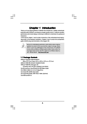
... Quick Installation Guide ASRock 775i915PL-M Support CD (including LGA 775 CPU Installation Live Demo) One 80-conductor Ultra ATA 66/100 IDE Ribbon Cable One Ribbon Cable for purchasing ASRock 775i915PL-M motherboard, a reliable motherboard produced under ASRock's consistently stringent quality control. ASRock website http://www.asrock.com 1.1 Package Contents ASRock 775i915PL-M Motherboard (Micro ATX Form Factor: 9.6-in x 8.6-in Floppy Drive One Serial ATA (SATA) Data Cable One Serial ATA (SATA) HDD Power Cable (Optional) One ASRock 8CH I/O 5 In this manual occur, the updated version will...
... Quick Installation Guide ASRock 775i915PL-M Support CD (including LGA 775 CPU Installation Live Demo) One 80-conductor Ultra ATA 66/100 IDE Ribbon Cable One Ribbon Cable for purchasing ASRock 775i915PL-M motherboard, a reliable motherboard produced under ASRock's consistently stringent quality control. ASRock website http://www.asrock.com 1.1 Package Contents ASRock 775i915PL-M Motherboard (Micro ATX Form Factor: 9.6-in x 8.6-in Floppy Drive One Serial ATA (SATA) Data Cable One Serial ATA (SATA) HDD Power Cable (Optional) One ASRock 8CH I/O 5 In this manual occur, the updated version will...
User Manual
Page 6
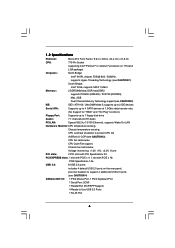
.../ Ultra DMA Mode 5, supports up to 2 IDE devices Serial ATA: Supports up to 4 SATA devices at 1.5Gb/s data transfer rate. (No Support for "RAID" and "Hot Plug" functions) Floppy Port: Supports up to 1 floppy disk drive Audio: 7.1 channels AC'97 Audio PCI LAN: Speed: 802.3u (10/100 Ethernet), supports Wake-On-LAN Hardware Monitor:CPU temperature sensing, Chassis temperature sensing, CPU overheat shutdown to -Use USB 2.0 Ports 1 RJ-45 Port 6 1.2 Specifications Platform: Micro ATX Form Factor: 9.6-in x 8.6-in, 24.4 cm x 21.8 cm CPU: 775-Pin Socket supporting Intel® Pentium...
.../ Ultra DMA Mode 5, supports up to 2 IDE devices Serial ATA: Supports up to 4 SATA devices at 1.5Gb/s data transfer rate. (No Support for "RAID" and "Hot Plug" functions) Floppy Port: Supports up to 1 floppy disk drive Audio: 7.1 channels AC'97 Audio PCI LAN: Speed: 802.3u (10/100 Ethernet), supports Wake-On-LAN Hardware Monitor:CPU temperature sensing, Chassis temperature sensing, CPU overheat shutdown to -Use USB 2.0 Ports 1 RJ-45 Port 6 1.2 Specifications Platform: Micro ATX Form Factor: 9.6-in x 8.6-in, 24.4 cm x 21.8 cm CPU: 775-Pin Socket supporting Intel® Pentium...
User Manual
Page 7
... BIOS, Supports "Plug and Play", ACPI 1.1 compliance wake up events, Supports jumperfree, CPU frequency stepless control (only for USB 2.0 works fine under Microsoft® Windows® XP SP1 / 2000 SP4. 5. About the setting of "Device Manager". This motherboard supports Dual Channel Memory Technology. While CPU overheat is not recommended to spray thermal grease between the CPU and the heatsink when you implement Dual Channel Memory Technology, make sure to read the installation guide of memory modules on page 9 for proper installation. 3. Power...
... BIOS, Supports "Plug and Play", ACPI 1.1 compliance wake up events, Supports jumperfree, CPU frequency stepless control (only for USB 2.0 works fine under Microsoft® Windows® XP SP1 / 2000 SP4. 5. About the setting of "Device Manager". This motherboard supports Dual Channel Memory Technology. While CPU overheat is not recommended to spray thermal grease between the CPU and the heatsink when you implement Dual Channel Memory Technology, make sure to read the installation guide of memory modules on page 9 for proper installation. 3. Power...
User Manual
Page 8
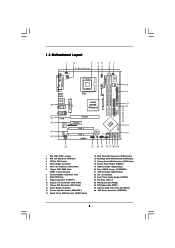
... 1 HDLED RESET SATA1 SATA2 SATA3 SATA4 775i915PL-M PCI EXPRESS 24.4cm (9.6 in) 8 9 10 11 12 13 22 21 20 19 18 17 161514 1 PS2_USB_PWR1 Jumper 2 ATX 12V Connector (ATX12V1) 3 775-Pin CPU Socket 4 North Bridge Controller 5 CPU Fan Connector (CPU_FAN1) 6 184-pin DDR DIMM Slots (DDR1- 2, Dual Channel) 7 Infrared Module Connector (IR1) 8 BIOS FWH Chip 9 Floppy Connector (FLOPPY1) 10 Chassis Fan Connector (CHA_FAN1) 11 Primary IDE Connector (IDE1, Black) 12 South Bridge Controller 13 Chassis Speaker Header (SPEAKER 1) 14 Fourth Serial ATA Connector (SATA4, black...
... 1 HDLED RESET SATA1 SATA2 SATA3 SATA4 775i915PL-M PCI EXPRESS 24.4cm (9.6 in) 8 9 10 11 12 13 22 21 20 19 18 17 161514 1 PS2_USB_PWR1 Jumper 2 ATX 12V Connector (ATX12V1) 3 775-Pin CPU Socket 4 North Bridge Controller 5 CPU Fan Connector (CPU_FAN1) 6 184-pin DDR DIMM Slots (DDR1- 2, Dual Channel) 7 Infrared Module Connector (IR1) 8 BIOS FWH Chip 9 Floppy Connector (FLOPPY1) 10 Chassis Fan Connector (CHA_FAN1) 11 Primary IDE Connector (IDE1, Black) 12 South Bridge Controller 13 Chassis Speaker Header (SPEAKER 1) 14 Fourth Serial ATA Connector (SATA4, black...
User Manual
Page 9
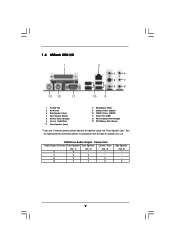
... In (Light Blue) * 7 Front Speaker (Lime) 8 Microphone (Pink) 9 USB 2.0 Ports (USB01) 10 USB 2.0 Ports (USB23) 11 Serial Port: COM1 12 PS/2 Keyboard Port (Purple) 13 PS/2 Mouse Port (Green) * If you use 2-channel speaker, please connect the speaker's plug into "Front Speaker Jack". See the table below for Audio Output Connection Audio Output Channels Front Speaker Rear Speaker Central / Bass (No. 7) (No. 4) (No. 5) 2 V -- -- 4 V V -- 6 V V V 8 V V V Side Speaker (No. 3) ---V 9 TABLE for connection details in accordance with the type of speaker you use .
... In (Light Blue) * 7 Front Speaker (Lime) 8 Microphone (Pink) 9 USB 2.0 Ports (USB01) 10 USB 2.0 Ports (USB23) 11 Serial Port: COM1 12 PS/2 Keyboard Port (Purple) 13 PS/2 Mouse Port (Green) * If you use 2-channel speaker, please connect the speaker's plug into "Front Speaker Jack". See the table below for Audio Output Connection Audio Output Channels Front Speaker Rear Speaker Central / Bass (No. 7) (No. 4) (No. 5) 2 V -- -- 4 V V -- 6 V V V 8 V V V Side Speaker (No. 3) ---V 9 TABLE for connection details in accordance with the type of speaker you use .
User Manual
Page 13
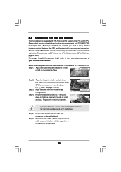
... on side closest to the CPU fan connector on the motherboard. Step 3. Align fasteners with remaining fasteners. Connect fan header with the CPU fan connector on the motherboard (CPU_FAN1, see page 8, No. 5). Ensure that supports Intel 775-LAND CPU. Step 2. Then connect the CPU fan to improve heat dissipation. Step 1. Step 6. Before you installed the heatsink, you press down on the socket surface. Ensure fan cables are securely fastened and in...
... on side closest to the CPU fan connector on the motherboard. Step 3. Align fasteners with remaining fasteners. Connect fan header with the CPU fan connector on the motherboard (CPU_FAN1, see page 8, No. 5). Ensure that supports Intel 775-LAND CPU. Step 2. Then connect the CPU fan to improve heat dissipation. Step 1. Step 6. Before you installed the heatsink, you press down on the socket surface. Ensure fan cables are securely fastened and in...
User Manual
Page 16
... Short pin2, pin3 to enable +5VSB (standby) for 15 seconds, use a jumper cap to clear the CMOS when you just finish updating the BIOS, you must boot up events. Clear CMOS (CLRCMOS1, 2-pin jumper) (see p.8 No. 22) JR1 JL1 Note: If the jumpers JL1 and JR1 are setup. With the external add-on PCI Express VGA card, you to default setup, please turn off the computer and unplug the power cord from the power supply...
... Short pin2, pin3 to enable +5VSB (standby) for 15 seconds, use a jumper cap to clear the CMOS when you just finish updating the BIOS, you must boot up events. Clear CMOS (CLRCMOS1, 2-pin jumper) (see p.8 No. 22) JR1 JL1 Note: If the jumpers JL1 and JR1 are setup. With the external add-on PCI Express VGA card, you to default setup, please turn off the computer and unplug the power cord from the power supply...
User Manual
Page 18
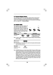
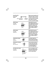
... GND CD-L CD1 ASRock 8CH I /O accommodates 4 default USB 2.0 ports. USB 2.0 Header (9-pin USB67) (see p.8 No. 23) GND +5VA BACKOUT-R BACKOUT-L 1 A U D - Front Panel Audio Header (9-pin AUDIO1) (see p.8 No. 19) USB_PWR P-6 P+6 GND DUMMY 1 GND P+7 P-7 USB_PWR ASRock 8CH I /O accommodates 4 default USB 2.0 ports. Serial ATA (SATA) Power Cable (Optional) connect to the SATA HDD power connector connect to the power supply Please connect the black end of SATA power cable to the power connector of audio devices. 18 This header supports an optional wireless transmitting and...
... GND CD-L CD1 ASRock 8CH I /O accommodates 4 default USB 2.0 ports. USB 2.0 Header (9-pin USB67) (see p.8 No. 23) GND +5VA BACKOUT-R BACKOUT-L 1 A U D - Front Panel Audio Header (9-pin AUDIO1) (see p.8 No. 19) USB_PWR P-6 P+6 GND DUMMY 1 GND P+7 P-7 USB_PWR ASRock 8CH I /O accommodates 4 default USB 2.0 ports. Serial ATA (SATA) Power Cable (Optional) connect to the SATA HDD power connector connect to the power supply Please connect the black end of SATA power cable to the power connector of audio devices. 18 This header supports an optional wireless transmitting and...
User Manual
Page 22
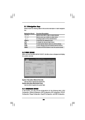
... section, you enter the BIOS SETUP UTILITY, the Main screen will appear and display the system overview BIOS SETUP UTILITY Main Advanced H/W Monitor Boot Security Exit System Overview System Time System Date [14:00:09] [Thu 05/05/2005] BIOS Version : 775i915PL-M BIOS P1.00 Processor Type : Intel (R) CPU 3.60 GHz Processor Speed : 3600 MHz Microcode Update : F43/04 Cache Size : 2048KB Total Memory DIMM 1 DIMM 2 : 512MB Dual-Channel Memory Mode : 256MB/166MHz (DDR333) : 256MB/166MHz (DDR333) Use [Enter], [TAB] or...
... section, you enter the BIOS SETUP UTILITY, the Main screen will appear and display the system overview BIOS SETUP UTILITY Main Advanced H/W Monitor Boot Security Exit System Overview System Time System Date [14:00:09] [Thu 05/05/2005] BIOS Version : 775i915PL-M BIOS P1.00 Processor Type : Intel (R) CPU 3.60 GHz Processor Speed : 3600 MHz Microcode Update : F43/04 Cache Size : 2048KB Total Memory DIMM 1 DIMM 2 : 512MB Dual-Channel Memory Mode : 256MB/166MHz (DDR333) : 256MB/166MHz (DDR333) Use [Enter], [TAB] or...
User Manual
Page 23
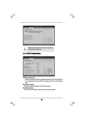
... to malfunction. 3.3.1 CPU Configuration BIOS SETUP UTILITY Advanced CPU Configuration CPU Host Frequency Actual Frequency (MHz) Boot Failure Guard Spread Spectrum Ratio Status Ratio Actual Value CPU Thermal Throttling Hyper Threading Technology Max CPUID Value Limit No-Excute Memory Protection Enhance Halt State Intel (R) SpeedStep(tm) tech. [Auto] [200] [Enabled] [Auto] Locked 18 [Enabled] [Auto] [Disabled] [Disabled] [Disabled] [Auto] Select how to set the CPU host frequency. +F1 F9 F10 ESC Select Screen Select Item Change Option General Help Load Defaults Save and...
... to malfunction. 3.3.1 CPU Configuration BIOS SETUP UTILITY Advanced CPU Configuration CPU Host Frequency Actual Frequency (MHz) Boot Failure Guard Spread Spectrum Ratio Status Ratio Actual Value CPU Thermal Throttling Hyper Threading Technology Max CPUID Value Limit No-Excute Memory Protection Enhance Halt State Intel (R) SpeedStep(tm) tech. [Auto] [200] [Enabled] [Auto] Locked 18 [Enabled] [Auto] [Disabled] [Disabled] [Disabled] [Auto] Select how to set the CPU host frequency. +F1 F9 F10 ESC Select Screen Select Item Change Option General Help Load Defaults Save and...
User Manual
Page 24
... displays the ratio actual value of this motherboard. Max CPUID Value Limit For Prescott CPU only, some OSes (ex. No-Excute Memory Protection No-Execution (NX) Memory Protection Technology is supported through the native processor instructions HLT and MWAIT and requires no hardware support from the chipset. An IA-32 processor with "No Execute (NX) Memory Protection" can switch between multiple frequency and voltage points to execute code...
... displays the ratio actual value of this motherboard. Max CPUID Value Limit For Prescott CPU only, some OSes (ex. No-Excute Memory Protection No-Execution (NX) Memory Protection Technology is supported through the native processor instructions HLT and MWAIT and requires no hardware support from the chipset. An IA-32 processor with "No Execute (NX) Memory Protection" can switch between multiple frequency and voltage points to execute code...
User Manual
Page 25
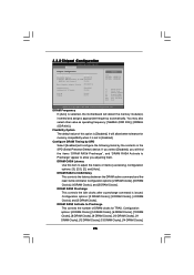
...[Auto] Boot Graphic Adapter Priority [PCIE/PCI] OnBoard LAN OnBoard AC'97 Audio [Enabled] [Auto] VCCM VDDQ [Auto] [Low] Options Auto 166MHz (DDR333) 200MHz (DDR400) +F1 F9 F10 ESC Select Screen Select Item Change Option General Help Load Defaults Save and Exit Exit v02.54 (C) Copyright 1985-2005, American Megatrends, Inc. Configuration options: [2 DRAM Clocks], [3 DRAM Clocks], [4 DRAM Clocks], and [5 DRAM Clocks]. DRAM CAS# Latency Use this option is issued. Configuration options: [4 DRAM Clocks], [5 DRAM Clocks], [6 DRAM Clocks], [7 DRAM Clocks], [8 DRAM Clocks], [9 DRAM Clocks...
...[Auto] Boot Graphic Adapter Priority [PCIE/PCI] OnBoard LAN OnBoard AC'97 Audio [Enabled] [Auto] VCCM VDDQ [Auto] [Low] Options Auto 166MHz (DDR333) 200MHz (DDR400) +F1 F9 F10 ESC Select Screen Select Item Change Option General Help Load Defaults Save and Exit Exit v02.54 (C) Copyright 1985-2005, American Megatrends, Inc. Configuration options: [2 DRAM Clocks], [3 DRAM Clocks], [4 DRAM Clocks], and [5 DRAM Clocks]. DRAM CAS# Latency Use this option is issued. Configuration options: [4 DRAM Clocks], [5 DRAM Clocks], [6 DRAM Clocks], [7 DRAM Clocks], [8 DRAM Clocks], [9 DRAM Clocks...
User Manual
Page 26
... system starts to set the power state after an unexpected AC/ Power loss. The default value of this feature is [Low]. 3.3.3 ACPI Configuration BIOS SETUP UTILITY Advanced ACPI Configuration Suspend To RAM Restore on AC/Power Loss This allows you to boot up when the power recovers. If [Power Off] is [PCIE/PCI]. Configuration options: [High], [Low],and [Auto]. VDDQ Use this to enable or disable the "OnBoard LAN" feature. Boot Graphic Adapter Priority This allows you to select VCCM. OnBoard LAN...
... system starts to set the power state after an unexpected AC/ Power loss. The default value of this feature is [Low]. 3.3.3 ACPI Configuration BIOS SETUP UTILITY Advanced ACPI Configuration Suspend To RAM Restore on AC/Power Loss This allows you to boot up when the power recovers. If [Power Off] is [PCIE/PCI]. Configuration options: [High], [Low],and [Auto]. VDDQ Use this to enable or disable the "OnBoard LAN" feature. Boot Graphic Adapter Priority This allows you to select VCCM. OnBoard LAN...
User Manual
Page 27
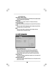
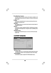
.... 3.3.4 IDE Configuration BIOS SETUP UTILITY Advanced IDE Configuration ATA/IDE Configuration SATA1 SATA2 SATA3 SATA4 IDE1 Master IDE1 Slave [Enhanced] [Hard Disk] [Not Detected] [Not Detected] [Not Detected] [ATAPI CDROM] [Not Detected] Set [Compatible] when Legacy OS (MS-DOS, WinMe / 98SE / NT) device is used. PS/2 Keyboard Power On Use this item to enable or disable RTC (Real Time Clock) to power on the system from the power-soft-off mode. RTC Alarm Power On Use this...
.... 3.3.4 IDE Configuration BIOS SETUP UTILITY Advanced IDE Configuration ATA/IDE Configuration SATA1 SATA2 SATA3 SATA4 IDE1 Master IDE1 Slave [Enhanced] [Hard Disk] [Not Detected] [Not Detected] [Not Detected] [ATAPI CDROM] [Not Detected] Set [Compatible] when Legacy OS (MS-DOS, WinMe / 98SE / NT) device is used. PS/2 Keyboard Power On Use this item to enable or disable RTC (Real Time Clock) to power on the system from the power-soft-off mode. RTC Alarm Power On Use this...
User Manual
Page 29
... default value of PCI clocks for compatible IDE devices. Use this item to set the PIO mode to enable or disable the S.M.A.R.T. (Self-Monitoring, Analysis, and Reporting Technology) feature. PIO Mode Use this item to enhance hard disk performance by reading or writing more data during each transfer. If this item is recommended to enable or disable the PCI IDE BusMaster feature. 29 Configuration options: [Disabled], [Auto], [Enabled]. 32-Bit Data Transfer Use this item to enable 32-bit access to...
... default value of PCI clocks for compatible IDE devices. Use this item to set the PIO mode to enable or disable the S.M.A.R.T. (Self-Monitoring, Analysis, and Reporting Technology) feature. PIO Mode Use this item to enhance hard disk performance by reading or writing more data during each transfer. If this item is recommended to enable or disable the PCI IDE BusMaster feature. 29 Configuration options: [Disabled], [Auto], [Enabled]. 32-Bit Data Transfer Use this item to enable 32-bit access to...
User Manual
Page 30
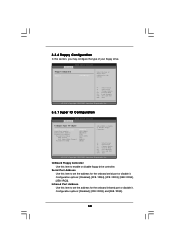
... onboard serial port or disable it . Serial Port Address Use this item to enable or disable floppy drive controller. Configuration options: [Disabled], [2F8 / IRQ3], and [2E8 / IRQ3]. 30 Infrared Port Address Use this section, you may configure the type of floppy drive connected to the system. +F1 F9 F10 ESC Select Screen Select Item Change Option General Help Load Defaults Save and Exit Exit v02.54 (C) Copyright 1985-2005, American Megatrends, Inc. 3.3.7 Super IO Configuration BIOS SETUP UTILITY Advanced Configure Super IO Chipset OnBoard Floppy Controller Serial Port...
... onboard serial port or disable it . Serial Port Address Use this item to enable or disable floppy drive controller. Configuration options: [Disabled], [2F8 / IRQ3], and [2E8 / IRQ3]. 30 Infrared Port Address Use this section, you may configure the type of floppy drive connected to the system. +F1 F9 F10 ESC Select Screen Select Item Change Option General Help Load Defaults Save and Exit Exit v02.54 (C) Copyright 1985-2005, American Megatrends, Inc. 3.3.7 Super IO Configuration BIOS SETUP UTILITY Advanced Configure Super IO Chipset OnBoard Floppy Controller Serial Port...
User Manual
Page 32
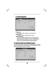
...USB device connected, "Auto" option will start to enable or disable the use of the CPU temperature, motherboard temperature, CPU fan speed, chassis fan speed, and the critical voltage. F1 F9 F10 ESC Select Screen Select Item General Help Load Defaults Save and Exit Exit v02.54 (C) Copyright 1985-2005, American Megatrends, Inc. 32 USB Controller Use this item to emulate legacy I/O devices such as mouse, keyboard,... BIOS SETUP UTILITY Main Advanced H/W Monitor Boot Security Exit Hardware Health Event Monitoring CPU Temperature M / B Temperature CPU Fan Speed Chassis Fan...
...USB device connected, "Auto" option will start to enable or disable the use of the CPU temperature, motherboard temperature, CPU fan speed, chassis fan speed, and the critical voltage. F1 F9 F10 ESC Select Screen Select Item General Help Load Defaults Save and Exit Exit v02.54 (C) Copyright 1985-2005, American Megatrends, Inc. 32 USB Controller Use this item to emulate legacy I/O devices such as mouse, keyboard,... BIOS SETUP UTILITY Main Advanced H/W Monitor Boot Security Exit Hardware Health Event Monitoring CPU Temperature M / B Temperature CPU Fan Speed Chassis Fan...

User Manual
Page 34
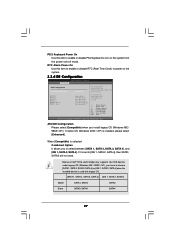
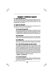
... 3.5.1 Boot Settings Configuration BIOS SETUP UTILITY Boot Boot Settings Configuration Boot From Network Bootup Num-Lock [Disabled] [On] To enable or disable the boot from network feature. +F1 F9 F10 ESC Select Screen Select Item Change Option General Help Load Defaults Save and Exit Exit v02.54 (C) Copyright 1985-2005, American Megatrends, Inc. BIOS SETUP UTILITY Main Advanced H/W Monitor Boot Security Exit Security Settings Supervisor Password : Not Installed User Password : Not Installed Change Supervisor Password Change User Password Install or Change the password.
... 3.5.1 Boot Settings Configuration BIOS SETUP UTILITY Boot Boot Settings Configuration Boot From Network Bootup Num-Lock [Disabled] [On] To enable or disable the boot from network feature. +F1 F9 F10 ESC Select Screen Select Item Change Option General Help Load Defaults Save and Exit Exit v02.54 (C) Copyright 1985-2005, American Megatrends, Inc. BIOS SETUP UTILITY Main Advanced H/W Monitor Boot Security Exit Security Settings Supervisor Password : Not Installed User Password : Not Installed Change Supervisor Password Change User Password Install or Change the password.
User Manual
Page 36
... ASRock's website at http://www.asrock.com; If the Main Menu did not appear automatically, locate and double click on a specific item then follow the installation wizard to install it has several tiny pins, whcih are easily to your computer. or you start the installation of CPU and motherboard damages caused by any improper handling. Because motherboard settings and hardware options vary, use the setup procedures in the motherboard's Support...
... ASRock's website at http://www.asrock.com; If the Main Menu did not appear automatically, locate and double click on a specific item then follow the installation wizard to install it has several tiny pins, whcih are easily to your computer. or you start the installation of CPU and motherboard damages caused by any improper handling. Because motherboard settings and hardware options vary, use the setup procedures in the motherboard's Support...


