User Manual
Page 8
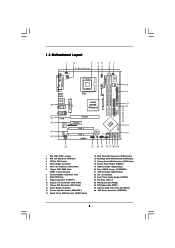
... IDE1 PCIE2 ` PCI 1 PCI 2 USB2.0 IntIeClH6 CMOS Battery SPEAKER1 1 USB45 USB67 1 1 CLRCMOS1 1 USB45 PANEL1 PLED PWRBTN 1 HDLED RESET SATA1 SATA2 SATA3 SATA4 775i915PL-M PCI EXPRESS 24.4cm (9.6 in) 8 9 10 11 12 13 22 21 20 19 18 17 161514 1 PS2_USB_PWR1 Jumper 2 ATX 12V Connector (ATX12V1...Speaker Header (SPEAKER 1) 14 Fourth Serial ATA Connector (SATA4, black) 15 Third Serial ATA Connector (SATA3, black) 16 Secondary Serial ATA Connector (SATA2, blue) 17 Primary Serial ATA Connector (SATA1, blue) 18 System Panel Header (PANEL1) 19 USB 2.0 Header (USB67, Blue) 20 Clear CMOS...
... IDE1 PCIE2 ` PCI 1 PCI 2 USB2.0 IntIeClH6 CMOS Battery SPEAKER1 1 USB45 USB67 1 1 CLRCMOS1 1 USB45 PANEL1 PLED PWRBTN 1 HDLED RESET SATA1 SATA2 SATA3 SATA4 775i915PL-M PCI EXPRESS 24.4cm (9.6 in) 8 9 10 11 12 13 22 21 20 19 18 17 161514 1 PS2_USB_PWR1 Jumper 2 ATX 12V Connector (ATX12V1...Speaker Header (SPEAKER 1) 14 Fourth Serial ATA Connector (SATA4, black) 15 Third Serial ATA Connector (SATA3, black) 16 Secondary Serial ATA Connector (SATA2, blue) 17 Primary Serial ATA Connector (SATA1, blue) 18 System Panel Header (PANEL1) 19 USB 2.0 Header (USB67, Blue) 20 Clear CMOS...
User Manual
Page 15
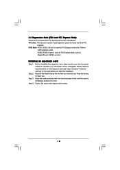
... to the chassis with screws. 15 Step 2. Step 4. PCIE2 (PCIE x4 slot) is unplugged. Keep the screws for PCI Express cards, such as GigaLAN card, SATA2 card, etc.
... to the chassis with screws. 15 Step 2. Step 4. PCIE2 (PCIE x4 slot) is unplugged. Keep the screws for PCI Express cards, such as GigaLAN card, SATA2 card, etc.
User Manual
Page 17
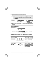
...jumpers. Serial ATA (SATA) Data Cable Either end of the connector. Primary IDE connector (Blue) (39-pin IDE1, see p.8 No. 14) SATA1 SATA2 SATA3 SATA4 These four Serial ATA (SATA) connectors support SATA data cables for the details. The current SATA interface allows up to the SATA hard... over the headers and connectors will cause permanent damage of your IDE device vendor for internal storage devices. Serial ATA Connectors (SATA1: see p.8 No. 17) (SATA2: see p.8 No. 16) (SATA3: see p.8 No. 15) (SATA4: see p.8 No. 11) PIN1 IDE1 connect the blue end connect the black end to...
...jumpers. Serial ATA (SATA) Data Cable Either end of the connector. Primary IDE connector (Blue) (39-pin IDE1, see p.8 No. 14) SATA1 SATA2 SATA3 SATA4 These four Serial ATA (SATA) connectors support SATA data cables for the details. The current SATA interface allows up to the SATA hard... over the headers and connectors will cause permanent damage of your IDE device vendor for internal storage devices. Serial ATA Connectors (SATA1: see p.8 No. 17) (SATA2: see p.8 No. 16) (SATA3: see p.8 No. 15) (SATA4: see p.8 No. 11) PIN1 IDE1 connect the blue end connect the black end to...
User Manual
Page 27
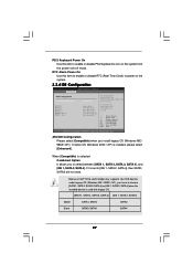
..., SATA3 will not work. When [Compatible] is used with legacy OS. [SATA 1, SATA 2, SATA 3, SATA 4] [IDE 1, SATA 2, SATA 4] Master SATA1, SATA2 SATA2 Slave SATA3, SATA4 SATA4 27 PS/2 Keyboard Power On Use this item to enable or disable RTC (Real Time Clock) to power on the system...item to enable or disable PS/2 keyboard to turn on the system. 3.3.4 IDE Configuration BIOS SETUP UTILITY Advanced IDE Configuration ATA/IDE Configuration SATA1 SATA2 SATA3 SATA4 IDE1 Master IDE1 Slave [Enhanced] [Hard Disk] [Not Detected] [Not Detected] [Not Detected] [ATAPI CDROM] [Not Detected] ...
..., SATA3 will not work. When [Compatible] is used with legacy OS. [SATA 1, SATA 2, SATA 3, SATA 4] [IDE 1, SATA 2, SATA 4] Master SATA1, SATA2 SATA2 Slave SATA3, SATA4 SATA4 27 PS/2 Keyboard Power On Use this item to enable or disable RTC (Real Time Clock) to power on the system...item to enable or disable PS/2 keyboard to turn on the system. 3.3.4 IDE Configuration BIOS SETUP UTILITY Advanced IDE Configuration ATA/IDE Configuration SATA1 SATA2 SATA3 SATA4 IDE1 Master IDE1 Slave [Enhanced] [Hard Disk] [Not Detected] [Not Detected] [Not Detected] [ATAPI CDROM] [Not Detected] ...
