User Manual
Page 3
...5 1.1 Package Contents 5 1.2 Specifications 6 1.3 Motherboard Layout 8 1.4 ASRock I/O PlusTM 9 2 Installation 10 2.1 Screw Holes 10 2.2 Pre-installation Precautions 10 2.3 CPU Installation 11 2.4 Installation of CPU Fan and Heatsink 13 2.5 Installation of Memory Modules (DIMM 14 2.6 ... 21 3.1 Introduction 21 3.1.1 BIOS Menu Bar 21 3.1.2 Navigation Keys 22 3.2 Main Screen 22 3.3 Advanced Screen 23 3.3.1 CPU Configuration 23 3.3.2 Chipset Configuration 24 3.3.3 ACPI Configuration 26 3.3.4 IDE Configuration 27 3.3.5 PCIPnP Configuration 29 3.3.6 Floppy Configuration 30 ...
...5 1.1 Package Contents 5 1.2 Specifications 6 1.3 Motherboard Layout 8 1.4 ASRock I/O PlusTM 9 2 Installation 10 2.1 Screw Holes 10 2.2 Pre-installation Precautions 10 2.3 CPU Installation 11 2.4 Installation of CPU Fan and Heatsink 13 2.5 Installation of Memory Modules (DIMM 14 2.6 ... 21 3.1 Introduction 21 3.1.1 BIOS Menu Bar 21 3.1.2 Navigation Keys 22 3.2 Main Screen 22 3.3 Advanced Screen 23 3.3.1 CPU Configuration 23 3.3.2 Chipset Configuration 24 3.3.3 ACPI Configuration 26 3.3.4 IDE Configuration 27 3.3.5 PCIPnP Configuration 29 3.3.6 Floppy Configuration 30 ...
User Manual
Page 4
4 Software Support 36 4.1 Install Operating System 36 4.2 Support CD Information 36 4.2.1 Running Support CD 36 4.2.2 Drivers Menu 36 4.2.3 Utilities Menu 36 4.2.4 ASRock "PC-DIY Live Demo" Program 36 4.2.5 "LGA 775 CPU Installation Live Demo" Program.... 36 4.2.6 Contact Information 36 4
4 Software Support 36 4.1 Install Operating System 36 4.2 Support CD Information 36 4.2.1 Running Support CD 36 4.2.2 Drivers Menu 36 4.2.3 Utilities Menu 36 4.2.4 ASRock "PC-DIY Live Demo" Program 36 4.2.5 "LGA 775 CPU Installation Live Demo" Program.... 36 4.2.6 Contact Information 36 4
User Manual
Page 5
... One Serial ATA (SATA) Data Cable One Serial ATA (SATA) HDD Power Cable (Optional) One ASRock I/O PlusTM Shield 5 Chapter 1 Introduction Thank you for a 3.5-in , 30.5 cm x 18.3 cm) ASRock 775i48 Quick Installation Guide ASRock 775i48 Support CD (including LGA 775 CPU Installation Live Demo) One 80-conductor Ultra ATA 66/100 IDE Ribbon Cable One Ribbon...
... One Serial ATA (SATA) Data Cable One Serial ATA (SATA) HDD Power Cable (Optional) One ASRock I/O PlusTM Shield 5 Chapter 1 Introduction Thank you for a 3.5-in , 30.5 cm x 18.3 cm) ASRock 775i48 Quick Installation Guide ASRock 775i48 Support CD (including LGA 775 CPU Installation Live Demo) One 80-conductor Ultra ATA 66/100 IDE Ribbon Cable One Ribbon...
User Manual
Page 6
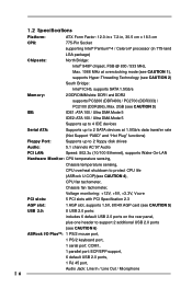
...PCI LAN: Speed: 802.3u (10/100 Ethernet), supports Wake-On-LAN Hardware Monitor: CPU temperature sensing, Chassis temperature sensing, CPU overheat shutdown to protect CPU life (ASRock U-COP)(see CAUTION 4), CPU fan tachometer, Chassis fan tachometer, Voltage monitoring: +12V, +5V, +3.3V, Vcore ...USB 2.0: 8 USB 2.0 ports: includes 6 default USB 2.0 ports on the rear panel, plus one header to support 2 additional USB 2.0 ports (see CAUTION 6) ASRock I/O PlusTM: 1 PS/2 mouse port, 1 PS/2 keyboard port, 1 serial port: COM1, 1 parallel port: ECP/EPP support, 6 default USB 2.0 ports,...
...PCI LAN: Speed: 802.3u (10/100 Ethernet), supports Wake-On-LAN Hardware Monitor: CPU temperature sensing, Chassis temperature sensing, CPU overheat shutdown to protect CPU life (ASRock U-COP)(see CAUTION 4), CPU fan tachometer, Chassis fan tachometer, Voltage monitoring: +12V, +5V, +3.3V, Vcore ...USB 2.0: 8 USB 2.0 ports: includes 6 default USB 2.0 ports on the rear panel, plus one header to support 2 additional USB 2.0 ports (see CAUTION 6) ASRock I/O PlusTM: 1 PS/2 mouse port, 1 PS/2 keyboard port, 1 serial port: COM1, 1 parallel port: ECP/EPP support, 6 default USB 2.0 ports,...

User Manual
Page 7
... run at DDR320 if you resume the system, please check if the CPU fan on the motherboard functions properly and unplug the power cord, then plug it will automatically shutdown. CPU FSB Frequency Memory Support Frequency 800 DDR266, DDR320*, DDR400 533 DDR266, DDR333...and Play", ACPI 1.1 compliance wake up events, Supports jumperfree, SMBIOS 2.3.1 support, CPU frequency stepless control (only for advanced users' reference, see page 16). 2. While CPU overheat is not recommended to support FSB1066 CPU, please adjust your FSB1 jumper setting, and short pin2 and pin3 (see CAUTION...
... run at DDR320 if you resume the system, please check if the CPU fan on the motherboard functions properly and unplug the power cord, then plug it will automatically shutdown. CPU FSB Frequency Memory Support Frequency 800 DDR266, DDR320*, DDR400 533 DDR266, DDR333...and Play", ACPI 1.1 compliance wake up events, Supports jumperfree, SMBIOS 2.3.1 support, CPU frequency stepless control (only for advanced users' reference, see page 16). 2. While CPU overheat is not recommended to support FSB1066 CPU, please adjust your FSB1 jumper setting, and short pin2 and pin3 (see CAUTION...

User Manual
Page 8
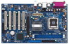
...USB5 CPU_FAN1 USB4_5 ATXPWR1 Intel 848P Chipset Super I/O IDE1 1 FSB1 AGP 8X 1.5V_AGP1 2Mb BIOS LAN PHY Audio CODEC JR1 JL1 1 AUDIO1 AUX1 CD1 PCI 1 775i48 PCI 2 PCI 3 5.1 CH USB2.0 PCI 4 PCI 5 GAME1 FLOPPY1 Intel ICH5 SATA1 SATA2 CMOS Battery S ATA CLRCMOS0 1 USB67 CHA_FAN1 1 IR1 1 ... 20 19 18 17 16 15 30.5cm (12.0in) 6 7 8 9 10 11 12 13 14 1 PS2_USB_PWR1 Jumper 2 ATX 12V Connector (ATX12V1) 3 775-Pin CPU Socket 4 North Bridge Controller 5 184-pin DDR DIMM Slots (DDR DIMM1- 2) 6 Secondary IDE Connector (IDE2, Black) 7 Primary IDE Connector (IDE1, Blue) 8 AGP...
...USB5 CPU_FAN1 USB4_5 ATXPWR1 Intel 848P Chipset Super I/O IDE1 1 FSB1 AGP 8X 1.5V_AGP1 2Mb BIOS LAN PHY Audio CODEC JR1 JL1 1 AUDIO1 AUX1 CD1 PCI 1 775i48 PCI 2 PCI 3 5.1 CH USB2.0 PCI 4 PCI 5 GAME1 FLOPPY1 Intel ICH5 SATA1 SATA2 CMOS Battery S ATA CLRCMOS0 1 USB67 CHA_FAN1 1 IR1 1 ... 20 19 18 17 16 15 30.5cm (12.0in) 6 7 8 9 10 11 12 13 14 1 PS2_USB_PWR1 Jumper 2 ATX 12V Connector (ATX12V1) 3 775-Pin CPU Socket 4 North Bridge Controller 5 184-pin DDR DIMM Slots (DDR DIMM1- 2) 6 Secondary IDE Connector (IDE2, Black) 7 Primary IDE Connector (IDE1, Blue) 8 AGP...
User Manual
Page 11
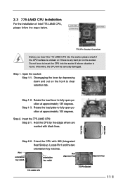
... 135 degrees. black line black line Step 2-2. Step 1. Rotate the load lever to fully open position at approximately 100 degrees. Hold the CPU by depressing down and out on the socket. Open the socket: Step 1-1. Disengaging the lever by the edges where are marked with IHS ... key notch orientation key notch Pin1 alignment key alignment key 775-LAND CPU 775-Pin Socket 11 Locate Pin1 and the two orientation key notches. 2.3 775-LAND CPU Installation For the installation of Intel 775-LAND CPU, please follow the steps below. 775-Pin Socket Overview Before you ...
... 135 degrees. black line black line Step 2-2. Step 1. Rotate the load lever to fully open position at approximately 100 degrees. Hold the CPU by depressing down and out on the socket. Open the socket: Step 1-1. Disengaging the lever by the edges where are marked with IHS ... key notch orientation key notch Pin1 alignment key alignment key 775-LAND CPU 775-Pin Socket 11 Locate Pin1 and the two orientation key notches. 2.3 775-LAND CPU Installation For the installation of Intel 775-LAND CPU, please follow the steps below. 775-Pin Socket Overview Before you ...
User Manual
Page 12
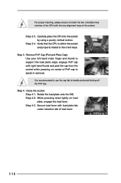
... recommended to use the cap tab to match the two orientation key notches of the CPU with load plate tab under retention tab of load lever. 12 Step 4-2. Remove PnP Cap (Pick and Place Cap): Use your left hand index finger ... socket. Secure load lever with the two alignment keys of PnP cap to the orient keys. Close the socket: Step 4-1. Step 2-4. Step 2-3. Carefully place the CPU into the socket by using a purely vertical motion. Step 3. Step 4-3.
... recommended to use the cap tab to match the two orientation key notches of the CPU with load plate tab under retention tab of load lever. 12 Step 4-2. Remove PnP Cap (Pick and Place Cap): Use your left hand index finger ... socket. Secure load lever with the two alignment keys of PnP cap to the orient keys. Close the socket: Step 4-1. Step 2-4. Step 2-3. Carefully place the CPU into the socket by using a purely vertical motion. Step 3. Step 4-3.
User Manual
Page 13
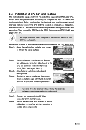
... IHS on the motherboard. If you need to spray thermal interface material between the CPU and the heatsink to illustrate the installation of the heatsink for 775-LAND CPU. Step 5. Connect fan header with the CPU fan connector on the socket surface. Please adopt the type of heatsink and cooling... fan compliant with 775-Pin socket that the CPU and the heatsink are oriented on side closest to install and lock. Below is equipped with Intel 775-LAND CPU to the CPU_FAN connector (CPU_FAN1, see page 8, No. 27). Align fasteners with remaining...
... IHS on the motherboard. If you need to spray thermal interface material between the CPU and the heatsink to illustrate the installation of the heatsink for 775-LAND CPU. Step 5. Connect fan header with the CPU fan connector on the socket surface. Please adopt the type of heatsink and cooling... fan compliant with 775-Pin socket that the CPU and the heatsink are oriented on side closest to install and lock. Below is equipped with Intel 775-LAND CPU to the CPU_FAN connector (CPU_FAN1, see page 8, No. 27). Align fasteners with remaining...
User Manual
Page 16
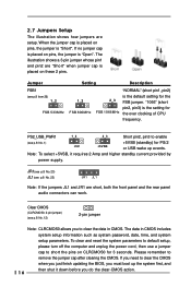
... down before you do the clear-CMOS action. 16 Clear CMOS (CLRCMOS0, 2-pin jumper) (see p.8 No. 1) +5VSB (standby) for FSB 1066MHz the over clocking of CPU frequency. JR1(see p.8 No. 23) JL1(see p.8 item 26) 1_2 FSB 533MHz Setting Description 1_2 FSB 800MHz "NORMAL" (short pin1, pin2) is "Short". If you...
... down before you do the clear-CMOS action. 16 Clear CMOS (CLRCMOS0, 2-pin jumper) (see p.8 No. 1) +5VSB (standby) for FSB 1066MHz the over clocking of CPU frequency. JR1(see p.8 No. 23) JL1(see p.8 item 26) 1_2 FSB 533MHz Setting Description 1_2 FSB 800MHz "NORMAL" (short pin1, pin2) is "Short". If you...
User Manual
Page 19
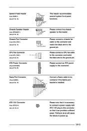
...+5V This header accommodates several system front panel functions. Failing to do so will cause the failure to power up. 19 Please connect a CPU fan cable to this connector and match the black wire to the ground pin. GND +12V CHA_FAN_SPEED Please connect a chassis fan cable to ...Panel Header (9-pin PANEL1) (see p.8 No. 15) Chassis Speaker Header (4-pin SPEAKER 1) (see p.8 No. 16) Chassis Fan Connector (3-pin CHA_FAN1) (see p.8 No. 13) CPU Fan Connector (4-pin CPU_FAN1) (see p.8 No. 27) ATX Power Connector (20-pin ATXPWR1) (see p.8, No. 2) +5V JBB1 JBX MIDI_OUT JBY JBB2 MIDI_IN 1 +5V JAB2 ...
...+5V This header accommodates several system front panel functions. Failing to do so will cause the failure to power up. 19 Please connect a CPU fan cable to this connector and match the black wire to the ground pin. GND +12V CHA_FAN_SPEED Please connect a chassis fan cable to ...Panel Header (9-pin PANEL1) (see p.8 No. 15) Chassis Speaker Header (4-pin SPEAKER 1) (see p.8 No. 16) Chassis Fan Connector (3-pin CHA_FAN1) (see p.8 No. 13) CPU Fan Connector (4-pin CPU_FAN1) (see p.8 No. 27) ATX Power Connector (20-pin ATXPWR1) (see p.8, No. 2) +5V JBB1 JBX MIDI_OUT JBY JBB2 MIDI_IN 1 +5V JAB2 ...
User Manual
Page 22
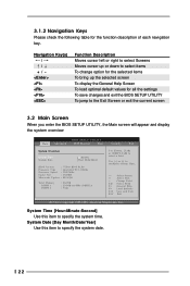
... UTILITY Main Advanced H/W Monitor Boot Security Exit System Overview System Time System Date [14:00:09] [Wed 10/06/2004] BIOS Version : 775i48 BIOS P1.00 Processor Type : Intel (R) CPU 3.20GHz Processor Speed : 3200 MHz Cache Size : 1024KB Microcode Update : 0F34/QE Total Memory DIMM 1 DIMM 2 : 256MB : 256MB/166MHz (DDR333) : None Use...
... UTILITY Main Advanced H/W Monitor Boot Security Exit System Overview System Time System Date [14:00:09] [Wed 10/06/2004] BIOS Version : 775i48 BIOS P1.00 Processor Type : Intel (R) CPU 3.20GHz Processor Speed : 3200 MHz Cache Size : 1024KB Microcode Update : 0F34/QE Total Memory DIMM 1 DIMM 2 : 256MB : 256MB/166MHz (DDR333) : None Use...
User Manual
Page 23
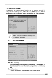
...to set the configurations for better system stability. 23 Setting wrong values in this motherboard. CPU Host Frequency While entering setup, BIOS auto detects the present CPU host frequency of this section may set the CPU host frequency. +F1 F9 F10 ESC Select Screen Select Item Change Option General Help ...Load Defaults Save and Exit Exit v02.54 (C) Copyright 1985-2003, American Megatrends, Inc. The actual CPU host frequency will show in below sections may cause system to Sub Screen F1 General Help F9 Load Defaults F10 Save and Exit ESC Exit...
...to set the configurations for better system stability. 23 Setting wrong values in this motherboard. CPU Host Frequency While entering setup, BIOS auto detects the present CPU host frequency of this section may set the CPU host frequency. +F1 F9 F10 ESC Select Screen Select Item Change Option General Help ...Load Defaults Save and Exit Exit v02.54 (C) Copyright 1985-2003, American Megatrends, Inc. The actual CPU host frequency will show in below sections may cause system to Sub Screen F1 General Help F9 Load Defaults F10 Save and Exit ESC Exit...
User Manual
Page 24
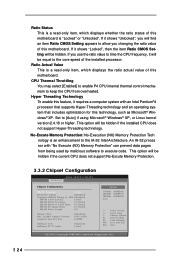
... software to execute code. This option will find an item Ratio CMOS Setting appears to allow you use the ratio value to time the CPU frequency, it shows "Unlocked", you will be equal to the core speed of the installed processor. An IA-32 proces sor with an...Technology To enable this feature, it shows "Locked", then the item Ratio CMOS Setting will be hidden. This option will be hidden if the installed CPU does not support Hyper-Threading technology. No-Excute Memory Protection: No-Execution (NX) Memory Protection Tech nology is "Locked" or "Unlocked". Ratio Actual...
... software to execute code. This option will find an item Ratio CMOS Setting appears to allow you use the ratio value to time the CPU frequency, it shows "Unlocked", you will be equal to the core speed of the installed processor. An IA-32 proces sor with an...Technology To enable this feature, it shows "Locked", then the item Ratio CMOS Setting will be hidden. This option will be hidden if the installed CPU does not support Hyper-Threading technology. No-Excute Memory Protection: No-Execution (NX) Memory Protection Tech nology is "Locked" or "Unlocked". Ratio Actual...
User Manual
Page 32
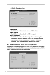
...legacy USB support. 3.4 Hardware Health Event Monitoring Screen In this item to enable or disable the use of the CPU temperature, motherboard temperature, CPU fan speed, chassis fan speed, and the critical voltage. 32 Main Advanced BIOS SETUP UTILITY H/W Monitor Boot ...Security Exit Hardware Health Event Monitoring CPU Temperature M / B Temperature CPU Fan Speed Chassis Fan Speed Vcore + 3.30V + 5.00V + 12.00V : 37 C / 98 F : 31 C / 87 F : 2463 RPM : N/A : 1.629V : ...
...legacy USB support. 3.4 Hardware Health Event Monitoring Screen In this item to enable or disable the use of the CPU temperature, motherboard temperature, CPU fan speed, chassis fan speed, and the critical voltage. 32 Main Advanced BIOS SETUP UTILITY H/W Monitor Boot ...Security Exit Hardware Health Event Monitoring CPU Temperature M / B Temperature CPU Fan Speed Chassis Fan Speed Vcore + 3.30V + 5.00V + 12.00V : 37 C / 98 F : 31 C / 87 F : 2463 RPM : N/A : 1.629V : ...
User Manual
Page 36
... you a multimedia PC-DIY live demo program before you start the installation of LGA 775 CPU in the motherboard's Support CD through this demo program, you need to contact ASRock or want to display the menus. 4.2.2 Drivers Menu The Drivers Menu shows the available devices drivers if... damages caused by step. To see this "LGA 775 CPU Installation Live Demo". You can run Microsoft® Media Player® to visit ASRock's website at http://www.asrock.com; Refer to your OS documentation for more about ASRock, welcome to play the file. The CD automatically displays the...
... you a multimedia PC-DIY live demo program before you start the installation of LGA 775 CPU in the motherboard's Support CD through this demo program, you need to contact ASRock or want to display the menus. 4.2.2 Drivers Menu The Drivers Menu shows the available devices drivers if... damages caused by step. To see this "LGA 775 CPU Installation Live Demo". You can run Microsoft® Media Player® to visit ASRock's website at http://www.asrock.com; Refer to your OS documentation for more about ASRock, welcome to play the file. The CD automatically displays the...


